
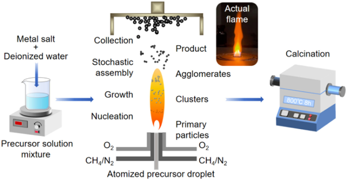
Figure 1.
Schematic of the FASP for preparing Co-free Ni-rich cathode materials.


In order to cope with global warming and energy shortages, the development of new energy systems is imminent. Therefore, the development of efficient energy conversion and energy storage technologies has attracted extensive attention from researchers [1]. Lithium-ion batteries (LIBs) have been widely used in portable electronic products, new energy electric vehicles, energy storage and other fields due to the advantages of high energy density, no memory effect and so on [2]. Nowadays, the popular cathode materials mainly include lithium manganese oxide (LiMn2O4), lithium iron phosphate (LiFePO4), and ternary cathode material (NCM: LiNi1-x-yCoxMnyO2). Among the cathode materials, ternary cathode materials, especially Ni-rich ternary cathode materials (NCM: LiNi1-x-yCoxMnyO2, 1-x-y ≥ 0.6) have high specific capacity and low cost, and are gradually becoming the preferred cathode material for high-performance lithium-ion batteries [3]. In ternary materials, Co is a key component for stabilizing the cathode [4]. However, owing to its lower abundance, high price and volatility, high toxicity and geopolitical issues, Co is considered the highest risk in the short term of the battery material supply chain, so it is necessary to lessen or eliminate Co in the cathode materials without sacrificing the performance of the battery [5]. Moreover, although Co is widely considered to improve the rate performance [6], the chemo-mechanical cracking and irreversible oxygen release of Co under high voltage are even more destructive than Ni [7,8]. Therefore, the next generation of high-performance lithium-ion batteries cathode materials tend to be Ni rich, Co-low or Co-free [9]. However, the inferior cycle stability of cobalt-free nickel-rich cathode materials hinders its further development.
Surface coating and bulk doping are two common approaches to improve the cycle performance of materials [10-12]. Compared with bulk doping, in order to achieve desirable properties, the thickness, morphology and crystallinity of the coating need to be precisely controlled, which is complicated and requires additional costs in cathode production [12]. Element doping is relatively simple, and very helpful to improve the cycle stability and rate performance of cathode materials. At present, Mg2+ with electrochemically inactive and Mo6+ with high-valence have attracted wide attention. Yang et al. [13] prepared Mg-doped Co-free Ni-rich cathode material LiNi0.5-xMgxMn0.5O2 (0 ≤ x ≤ 0.1), and found that Mg doping can reduce Li/Ni cation mixing, and 5% Mg doping has the best electrochemical performance. Tian et al. [14] improved the cycle performance and rate performance of Co-free Ni-rich cathode material by doping Mg, and the prepared LiNi0.90Mg0.05Mn0.05O2 has an initial discharge specific capacity of 194 mAh/g at 0.1 C. Sun et al. [15] successfully synthesized Mo-doped Co-free Ni-rich cathode material Mo-LiNi0.9Mn0.1O2 with improved cycle stability. The discharge specific capacity of Mo-LiNi0.9Mn0.1O2 is 215 mAh/g at 0.1 C, but the discharge specific capacity of undoped material LiNi0.9Mn0.1O2 is 230 mAh/g. Darbar et al. [16] reported that Mo-doped Co-free cathode material Mo-LiNi0.5Mn0.5O2 has a capacity retention of 65% after 100 cycles. From the above, it can be seen that the current element doping method is mainly single element. Although the cycle stability can be improved, the introduction of inactive elements usually leads to significant capacity decay.
Nowadays, the preparation methods of Ni-rich cathode materials mainly include co-precipitation method [17], solid-state method [18], sol-gel method [19], hydrothermal method [20] and so on. These traditional preparation methods usually have the disadvantages of complex steps, multiple pieces of equipment, and difficult separation of waste liquid by-products, which hinder the further development of cathode materials. Recently, flame-assisted spray pyrolysis (FASP), a novel preparation technique for nanostructured materials, has been proposed for the synthesis of cathode materials for lithium-ion batteries. In this method, the flame generated by the combustion reaction enthalpy change is used as the heat source to decompose the precursor aerosol, and then the nanostructured materials are synthesized. The basic principle and process can be briefly described as follows [21]. Firstly, the precursor droplets are sent into the flame field. Then under the action of high combustion temperature, the solvent evaporates rapidly, and the precursor compound pyrolyzes to produce primary particles. Immediately, under the action of chemical bonds, the primary particles agglomerate, nucleate, grow, and cluster, and finally form the target nanoparticle product. Compared with the traditional methods, FASP method has the advantages of short time, low cost and easy industrial scale-up [22]. Zhang et al. [23,24] prepared Li(Ni0.8Co0.1Mn0.1)O2 (NCM811) by FASP method, and explored the effects of preheating temperature and calcination temperature on the synthesized materials. Abram et al. [25] prepared Li(Ni1/3Co1/3Mn1/3)O2 (NCM111) and NCM811 by FASP method, and found that the material prepared at higher preheating temperature and lower flame temperature has better electrochemical properties. Yan et al. [26] used the same method to explore the effects of doping Dy on the cycle performance and thermochemical stability of NCM811. In general, there are very few studies on the preparation of cathode materials for lithium-ion batteries by FASP method, and mainly focus on ternary cathode materials, thus, there is a lack of research on Co-free Ni-rich cathode materials.
Overall, in order to address or alleviate the challenges of high capacity-good cycle stability incompatibility of Co-free Ni-rich cathode materials, the present study proposed the preparation of Mg-Mo double-element doped Co-free Ni-rich cathode material by developing the FASP method. The effects of Mg-Mo double element doping and flame temperature on the structure, morphology and electrochemical properties of the materials were investigated, which was then compared with the undoped Co-free Ni-rich cathode materials as well as the commercial Ni-rich cathode material NCM811. The Co-free Ni-rich cathode materials obtained under the conditions of 1–4 in Table S1 (Supporting information) are labeled as NM82–2073 K, NM82–1273 K, NM-MM-2073 K, and NM-MM-1273 K in turn.
The main experimental process of preparing Co-free Ni-rich cathode materials by FASP is illustrated in Fig. 1. The basic process can be briefly described as follows: The prepared precursor solution containing all the target elements was introduced into the flame field. Under the action of high temperature in the flame field, the precursor droplets underwent evaporation, decomposition, condensation, nucleation, growth, cluster and other processes to form the as-synthesized powder. Finally, the as-synthesized powder was calcined to obtain the cathode material.
Figs. 2a and b and Fig. S1 (Supporting information) show the XRD patterns and refinement results of NM-MM and NM82 cathode materials prepared at different flame temperatures. The diffraction peak positions of all samples are consistent with the standard card of LiNiO2, with the same α-NaFeO2 structure, and no impurity phase is observed, indicating that the crystal structure and phase composition are not affected by Mg and Mo doping. The (006)/(012) and (018)/(110) diffraction peaks are split, which indicates that all materials have obvious layered structure [17]. Due to the similar ionic radius of Ni2+ (0.69 Å) and Li+ (0.76 Å), Ni2+ is easy to enter the Li layer and cause the cation mixing. The Ni2+ entering the Li layer are located on the (104) crystal plane, which enhances the diffraction peak of (104) crystal plane. In addition, the intensity of (003) diffraction peak decreases with the decrease of lithium content, so the intensity ratio of (003) and (104) peaks I(003)/I(104) can be used to reflect the mixed level of cation mixing. Generally, a higher value of I(003)/I(104) indicates a lower level of cation mixing.
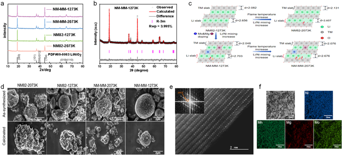
The structural parameters of all samples were Rietveld refined using GSAS II software [27]. The results are shown in Table S2 (Supporting information). The ratio of lattice parameter c to a (c/a) is usually used to represent triangular distortion [28]. The results show that the c/a values of all samples are greater than 4.9, indicating that the materials have an ordered layered structure. In the same material system with doped or undoped elements, the cation mixing level of samples prepared at higher flame temperature (2073 K) is higher than that at lower flame temperature (1273 K). This may be because higher flame temperature could lead to more lithium volatilization, thus improving the cation mixing level, the lithium content of the samples prepared at different flame temperatures is shown in Table S3 (Supporting information). Under the same flame temperature condition, the cation mixing level of the Mg-Mo two-element doped cathode material is higher than that of the undoped cathode material. This may be because after the high-valence element was doped, more Ni2+ was generated due to the charge conservation effect, thereby increasing the cation mixing level.
In order to further explore the relationship between element doping and the thickness of Li slab and TM slab, the thickness of Li slab and TM slab was calculated according to the refined results and Eq. S1 (Supporting information). The results are shown in the last two columns of Table S2. The variation of the Li/TM slab thickness probably relates to the difference of binding energy. The binding energy of Mo-O bond (607 kJ/mol) is greater than that of Ni-O bond (391 kJ/mol), Mn-O bond (402 kJ/mol) and Mg-O bond (394 kJ/mol) [29], so the lattice insertion of Mo enhances the attractiveness of TM-O. As shown in Fig. 2c, since O is shared by the Li-O and TM-O atoms in the lattice, the lattice insertion of tiny Mo strengthens the attraction of TM-O, resulting in the expansion of the Li slab and the contraction of the TM slab [30]. After doping with Mg and Mo, the expansion of the thickness of the Li slab is beneficial to the deintercalation of Li+. In addition, in the same material system of doped elements or undoped elements, the Li slab thickness of material prepared at higher flame temperature is smaller than that at lower flame temperature, which may be related to more lithium volatilization caused by higher temperature, which may be related to more lithium volatilization caused by higher flame temperature.
Fig. 2f and Fig. S2 (Supporting information) are the elements distribution mappings of NM82 and NM-MM cathode materials analyzed by EDS. It can be seen that the elements on the surface of the particles are uniformly distributed and no segregation occurs. The EDS scanning results of all samples are shown in Table S4 (Supporting information). It can be seen from Tables S3 and S4 that the elemental ratio of all samples is basically consistent with the solution ratio.
In order to further compare and analyze the effects of flame temperature and element doping on the microstructure of Co-free Ni-rich cathode materials, the materials before and after calcination were characterized by SEM. The results are shown in Fig. 2d. Before calcination, the material prepared at higher flame temperature exhibits a wrinkled spherical structure. At the same time, there are many small nanoparticles. These nanoparticles were not formed by a single droplet, but were formed by a gas phase nucleation mechanism. The precursor was vaporized, and then nucleated and grown in the form of gas phase to form small particles. Therefore, the higher flame temperature makes it easier for the material to be formed through the gas-to-particle path [25]. The material prepared at a lower flame temperature exhibits a spherical structure with a round drum, indicating that the material prepared at a lower flame temperature is more likely to be generated through the droplet-to-particle path, which may be preferable for the preparation the cathode materials.
After calcination, all materials exhibit an irregular spherical structure. Compared with the undoped materials, the primary particle size of the Mg-Mo doped materials became smaller. It can effectively dissipate the strain energy related to the harmful phase transition of H2-H3 [15]. The mechanical strain induced by the H2-H3 phase transition is sufficiently severe to nucleate microcracks along the primary particle boundaries. It has been reported that the most effective way to mechanically dissipate strain energy in brittle ceramic cathode materials is to reduce the primary particle size to an ultrafine size (<500 nm), thereby deflecting the crack path and safely absorbing the strain energy through the numerous grain boundaries generated by the ultrafine grains [31], therefore, the reduction of primary particle size can effectively prevent the propagation of microcracks. In addition, since the grain boundary diffusion is usually three to ten times faster than the bulk diffusion, the smaller primary particle size is beneficial to the rapid diffusion of Li+ [32,33], thereby preventing the inhomogeneity in the Li concentration of the cathode particle and avoiding the occurrence of intragranular fracture [15]. Therefore, the reduction of the primary particle size of the Mg-Mo doped materials can effectively prevent grain breakage.
The NM-MM-1273 K sample was further characterized by HRTEM to analyze the microstructure information of the material. As shown in Fig. 2e, the HRTEM image showed clear lattice fringes, and no other chaotic diffraction spots were found in the fast Fourier transform (FFT) image, manifesting good crystallinity of the material. In addition, the FFT image can be indexed as a layered phase with R
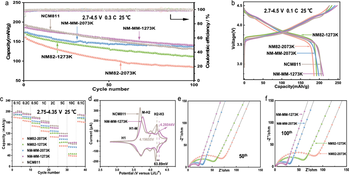
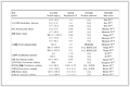
The cycle performance curves of doped materials, undoped materials and commercial material are shown in Fig. 3a. In the voltage range of 2.7–4.5 V, the current is 0.3 C. After 100 cycles, the Mg-Mo doped cathodes materials show good cycle stability, and their capacity retention rate and discharge specific capacity are better than those of undoped materials and commercial material. As shown in Table 1, the capacity retention rate of the doped material NM-MM-1273 K can reach 75.4% after 100 cycles, and the specific capacity is 140.4 mAh/g. The capacity retention rate of the undoped material NM82–1273 K is 65.0% after 100 cycles, and the specific capacity is only 112.2 mAh/g. The capacity retention rate of commercial NCM811 is 68.1% after 100 cycles, and the specific capacity is 131.0 mAh/g. These can be attributed to the following reasons: (1) Mg-Mo doping refines the primary particle size of the material, which effectively dissipates the strain energy related to the harmful phase transition of H2-H3 [29], thus inhibiting the generation and propagation of microcracks, which can hinder the direct contact between the material and the electrolyte to produce side reactions. Therefore, the cycle stability of the doped material is improved. (2) The refinement of the primary particle size after Mg-Mo doping is beneficial to the rapid diffusion of Li+ [33,34], which can prevent the uneven deposition of Li in the cathode particles, thus, avoiding the nucleation of intragranular fractures [31]. Therefore, the structural stability is enhanced. (3) Due to the similar ionic radius of Mg2+ and Li+, Mg2+ may occupy the Li+ sites and stabilize the layered structure, thereby enhancing the cycle stability.
 DownLoad:
CSV
| Sample | Initial discharge capacity at 0.1 C(mAh/g) | Discharge capacity at 10 C(mAh/g) | The first discharge capacity at 0.3 C(mAh/g) | The 100th discharge capacity at 0.3 C(mAh/g) | Capacity retention (%) |
| NM82–2073K | 185.9 | 39.2 | 160.7 | 84.8 | 52.8 |
| NM82–1273K | 193.0 | 45.2 | 172.6 | 112.2 | 65.0 |
| NM-MM-2073K | 198.8 | 71.1 | 174.0 | 137.4 | 79.0 |
| NM-MM-1273K | 210.5 | 86.1 | 186.2 | 140.4 | 75.4 |
| NCM811 | 205.5 | 84.3 | 192.5 | 131.0 | 68.1 |
The initial charge-discharge curves of Mg-Mo doped cathode materials, undoped cathode materials and commercial cathode material NCM811 in the voltage range of 2.7–4.5 V at 0.1 C current are shown in Fig. 3b. It can be seen that the initial discharge specific capacity of NM-MM-1273 K can reach 210.5 mAh/g, which is better than 205.5 mAh/g of commercial Ni-rich ternary cathode material NCM811, and the initial discharge specific capacity of NM82–1273 K is 193.0 mAh/g. Regardless of the flame temperature, the initial discharge specific capacity of the Mg-Mo doped materials is better than that of the undoped materials. In the same material system with doped or undoped elements, the initial discharge specific capacity of the material prepared at lower flame temperature is better than that at higher flame temperature. These can be attributed to the following reasons: (1) Mg-Mo doping expands the thickness of the Li slab of the material and refines the primary particle size, which is beneficial to the deintercalation of Li+. Therefore, the initial discharge specific capacity of the material increases after Mg-Mo doping. (2) During the charging process, Ni2+ in the Li sites is oxidized to smaller Ni3+/4+ (0.56 Å/0.53 Å), resulting in local collapse of the layered structure and hindering the further deintercalation of Li+ from the structure. The doping of Mg2+ in the Li slab can support the layered structure, inhibit the collapse of the structure, and promote the further deintercalation of Li+ [35]. Therefore, the doping of Mg and Mo can increase the discharge specific capacity. (3) In the same material system, the low level of cation mixing is beneficial to the deintercalation of Li+ between the lattices, so the initial discharge specific capacity of the materials prepared at lower flame temperature is better than that of the materials prepared at higher flame temperature. The rate performance of doped and undoped materials and commercial material is shown in Fig. 3c. At the voltage range of 2.75–4.35 V, the rate performance of NM-MM-1273 K is similar to that of commercial NCM811, and even the discharge specific capacity at high rate (10 C) is slightly better than that of commercial material. Regardless of the flame temperature, the rate performance of the Mg-Mo doped materials is better than that of the undoped materials. In the same material system, the rate performance of the materials prepared at lower flame temperature is better than that at higher flame temperature. The specific capacity of all samples can be recovered after charge-discharge test at different rates, indicating that the reversibility of all samples is good. These can be attributed to the following reasons: (1) The doping of Mg and Mo elements leads to the refinement of the primary particle size and the increase of the thickness of the Li slab, which shortens the diffusion path of Li+ and promotes the rapid deintercalation of Li+ [34]. In addition, it also reduces the barrier of Li+ diffusion and increases the diffusion rate of Li+ [33,36], thereby increasing the rate performance. (2) In the same material system, the materials prepared at lower flame temperature has a better layered structure, which is beneficial to the deintercalation of Li+.
The cyclic voltammetry (CV) curves are shown in Fig. 3d. Three pairs of oxidation/reduction peaks can be observed in all samples, indicating that all samples have undergone a typical nickel-rich material phase transition during charge and discharge: H1 (hexagonal phase) - M (monoclinic phase), M (monoclinic phase) - H2 (hexagonal phase), H2 (hexagonal phase) - H3 (hexagonal phase). Compared with commercial NCM811, the M-H2 redox peak in NM-MM is significantly flattened, and the redox peak of harmful H2-H3 phase transition shifts to a higher potential by 63.89 mV, indicating that the multi-step phase transitions in NM-MM are 'postponed' [37]. In addition, the H2-H3 redox peak potential of NM82 is similar to that of NM-MM.
Finally, in order to further study the effect of Mg-Mo doping on the electrochemical properties of the materials, the electrochemical impedance spectroscopy (EIS) test was carried out in this study. The EIS fitting curves are shown in Figs. 3e and f. The equivalent circuit model is used for fitting, where Rs represents the solution resistance, Rct represents the charge transfer resistance, CPE represents the constant phase element, and Wo (Warburg impedance) corresponds to the Li+ diffusion coefficient [38]. The fitting results are shown in Table S5 (Supporting information). In general, the high frequency half circle represents the Rs and CEI layers, the intermediate frequency half circle corresponds to Rct, and the slope of the straight line in the low frequency region represents the Warburg impedance. The Rct values of NM-MM-1273 K increased from 19.84 Ω (50th cycle) to 21.76 Ω (100th cycle), with the smallest change. In addition, the Rct values of Mg-Mo doped materials are lower than those of undoped materials, indicating that the insertion of Mg-Mo in the lattice not only reduces the impedance, but also inhibits the interface degradation. Moreover, the Mg-Mo doped materials exhibit a high slope, indicating that the lattice insertion of Mg-Mo increases the diffusion rate of Li+ [24]. In summary, the doping of Mg and Mo reduces the charge transfer resistance, inhibits the interface degradation, and also improves the diffusion rate of Li+, thus improving the electrochemical performance.
The primary objective of the present study was to prepare a Co-free Ni-rich cathode material, LiNi0.8Mn0.16Mg0.02Mo0.02O2(NM-MM), to achieve high capacity good cycle stability by flame-assisted spray pyrolysis in a one-step scheme. The effects of Mg-Mo dual-element doping on the structure, morphology and electrochemical properties of the NM-MM samples were investigated. Results show that the doping of Mg and Mo dual elements refines the primary particle size of the material, inhibits the generation and propagation of microcracks, stabilizes the layered structure, and is conducive to improving the cycle stability of the Co-free Ni-rich cathode material. At the same time, it increases the thickness of Li slab while refining the primary particle, which is beneficial to the rapid diffusion of Li+ and the improvement of specific capacity and rate performance. Therefore, the doping of Mg-Mo effectively improves the electrochemical performance. The initial discharge specific capacity at 0.1 C reaches 210.5 mAh/g, and the capacity retention rate after 100 cycles at 0.3 C is 75.4%. In addition, the flame temperature mainly affects the lithium volatilization and the path of particle nucleation. The materials prepared at lower flame temperature show better structure and better electrochemical performance. In summary, the present study indicates that flame-assisted spray pyrolysis provides a new and efficient method for the preparation of elemental doping modification for the Co-free Ni-rich cathode materials for lithium-ion batteries.
Jinyu Li: Writing – original draft, Methodology, Investigation, Formal analysis, Conceptualization. Junlei Wang: Formal analysis, Conceptualization. Shilong Li: Formal analysis, Conceptualization. Kun Wang: Writing – review & editing, Supervision, Resources, Formal analysis, Conceptualization.
The authors declare that they have no known competing financial interests or personal relationships that could have appeared to influence the work reported in this paper.
This study was supported by the National Natural Science Foundation of China (No. 52176124).
Supplementary material associated with this article can be found, in the online version, at doi:
K.C. Zhang, Y. Tian, X.J. Chen, et al., Chin. Chem. Lett. 35 (2024) 108308. doi: 10.1016/j.cclet.2023.108308
M.M. Zhou, J.J. Zhao, X.J. Wang, et al., Chin. Chem. Lett. 34 (2023) 107793. doi: 10.1016/j.cclet.2022.107793
Y.K. Sun, Z.H. Chen, H.J. Noh, et al., Nat. Mater. 11 (2012) 942–947. doi: 10.1038/nmat3435
W. Liu, P. Oh, X.E. Liu, et al., Angew. Chem. Int. Ed. 54 (2015) 4440–4457. doi: 10.1002/anie.201409262
M. Bianchini, M. Roca-Ayats, P. Haetmann, et al., Angew. Chem. Int. Ed. 58 (2019) 10434–10458. doi: 10.1002/anie.201812472
A. Manthiram, Nat. Commun. 11 (2020) 1550. doi: 10.1038/s41467-020-15355-0
T.C. Liu, L. Yu, J. Lu, et al., Nat. Energy 6 (2021) 277–286. doi: 10.1038/s41560-021-00776-y
J.Y. Li, C. Lin, M.Y. Weng, et al., Nat. Nanotechnol. 16 (2021) 599–605. doi: 10.1038/s41565-021-00855-x
L. Yu, H.A. Zhao, J.W. Sun, et al., Adv. Funct. Mater. 32 (2022) 2204931. doi: 10.1002/adfm.202204931
T. Weigel, F. Schipper, E.M. Erickson, et al., ACS Energy Lett. 4 (2019) 508– 516. doi: 10.1021/acsenergylett.8b02302
X.Y. Wang, B. Zhang, Z.M. Xiao, et al., Chin. Chem. Lett. 34 (2023) 107772. doi: 10.1016/j.cclet.2022.107772
M.K. Shobana, J. Alloys Compd. 802 (2019) 477–487. doi: 10.1016/j.jallcom.2019.06.194
G.W. Yang, E.Y. Zhao, M.M. Chen, et al., J. Solid State Electrochem. 21 (2017) 3195–3203. doi: 10.1007/s10008-017-3666-4
T. Rao, P. Gao, Z.M. Zhu, Solid State Ion. 376 (2022) 115860. doi: 10.1016/j.ssi.2022.115860
G.T. Park, B. Namkoong, S.B. Kin, et al., Nat. Energy 7 (2022) 946–954. doi: 10.1038/s41560-022-01106-6
D. Darbar, E.C. Self, L.Z. Li, et al., J. Power Sources 479 (2020) 228591. doi: 10.1016/j.jpowsour.2020.228591
M. Oljaca, B. Blizanac, A.D. Pasquier, et al., J. Power Sources 248 (2014) 729–738. doi: 10.1016/j.jpowsour.2013.09.102
W.Y. Zhang, X.C. Tang, L. Xiao, et al., J. Solid State Electrochem. 27 (2023) 1185–1194. doi: 10.1007/s10008-023-05427-8
H.Q. Lu, H.T. Zhou, A.M. Svensson, et al., Solid State Ion. 249-250 (2013) 105–111. doi: 10.1016/j.ssi.2013.07.023
H.J. Noh, S. Youn, C.S. Yoon, et al., J. Power Sources 233 (2013) 121–130. doi: 10.1016/j.jpowsour.2013.01.063
T. Tran-Phu, R. Daiyan, X.M.C. Ta, et al., Adv. Funct. Mater. 32 (2022) 2110020. doi: 10.1002/adfm.202110020
J.L. Wang, S.L. Li, W. Du, et al., Powder Technol. 464 (2025) 121233. doi: 10.1016/j.powtec.2025.121233
J.N. Zhang, V.L. Muldon, S.L. Deng, J. Power Sources 528 (2022) 231244. doi: 10.1016/j.jpowsour.2022.231244
J.N. Zhang, V.L. Muldon, S.L. Deng, Proc. Combust. Inst. 39 (2023) 1165–1173. doi: 10.1016/j.proci.2022.10.014
C. Abram, J.N. Shan, X.F. Yang, et al., ACS Appl. Energy Mater. 2 (2019) 1319–1329. doi: 10.1021/acsaem.8b01892
C. Yan, X.F. Yang, H. Zhao, et al., Proc. Combust. Inst. 38 (2021) 6623–6630. doi: 10.1016/j.proci.2020.06.332
B.H. Toby, R.B. Dreele, J. Appl. Crystallogr. 46 (2013) 544–549. doi: 10.1107/S0021889813003531
Z.D. Huang, X.M. Liu, S.W. Oh, et al., J. Mater. Chem. 21 (2011) 10777–10784. doi: 10.1039/c1jm00059d
Z.J. Huang, Z.X. Wang, X.B. Zheng, et al., Electrochim. Acta 182 (2015) 795–802. doi: 10.1016/j.electacta.2015.09.151
L. Qiao, Q. You, X.Y. Wu, et al., ACS Appl. Mater. Interfaces 16 (2024) 4772–4783. doi: 10.1021/acsami.3c16475
G.T. Park, D.R. Yoon, U.H. Kim, et al., Energy Environ. Sci. 14 (2021) 6616–6626. doi: 10.1039/d1ee02898g
S. Yang, B.G. Yan, L. Lu, et al., RSC Adv. 6 (2016) 94000–94009. doi: 10.1039/C6RA17681J
C. Schwab, A. Höweling, A. Windmüller, et al., Phys. Chem. Chem. Phys. 47 (2019) 26066–26076. doi: 10.1039/c9cp05128g
J.M. Zheng, P.F. Yan, L. Estevez, et al., Nano Energy 49 (2018) 538–548. doi: 10.1016/j.nanoen.2018.04.077
X.L. Liu, S. Wang, L. Wang, et al., J. Power Sources 438 (2019) 227017. doi: 10.1016/j.jpowsour.2019.227017
Z.L. Yu, X.Y. Qu, T. Wan, et al., ACS Appl. Mater. Interfaces 12 (2020) 40393–40403. doi: 10.1021/acsami.0c12541
R. Zhang, C.Y. Wang, P.C. Zou, et al., Nature 610 (2022) 67–73. doi: 10.1038/s41586-022-05115-z
T.X. Wang, M.L. Yuan, S. Xie, et al., Ceram. Int. 48 (2022) 20605–20611. doi: 10.1016/j.ceramint.2022.04.028

Figure 2 (a) Original XRD pattern of NM82 and NM-MM. (b) Rietveld refinement patterns of NM-MM-1273 K. (c) Schematic of crystal structure of the FASP-prepared samples. (d) SEM images of cathode materials before (top) and after (bottom) the calcination at different temperatures. (e) TEM images of NM-MM-1273 K. (f) EDS elemental mapping of Ni, Mn, Mg and Mo of NM-MM-1273 K.

Figure 3 Electrochemical performance for the FASP-prepared samples: (a) Long cycle at 0.3 C. (b) Initial charge/discharge curves at 0.1 C. (c) Rate performance. (d) CV curves of the second cycle. EIS of doped and undoped materials after (e) 50th and (f) 100th cycles.
Table 1. Electrochemical properties of the doped (NM-MM) and undoped materials (NM82), as well as the commercial material (NCM811).
| Sample | Initial discharge capacity at 0.1 C(mAh/g) | Discharge capacity at 10 C(mAh/g) | The first discharge capacity at 0.3 C(mAh/g) | The 100th discharge capacity at 0.3 C(mAh/g) | Capacity retention (%) |
| NM82–2073K | 185.9 | 39.2 | 160.7 | 84.8 | 52.8 |
| NM82–1273K | 193.0 | 45.2 | 172.6 | 112.2 | 65.0 |
| NM-MM-2073K | 198.8 | 71.1 | 174.0 | 137.4 | 79.0 |
| NM-MM-1273K | 210.5 | 86.1 | 186.2 | 140.4 | 75.4 |
| NCM811 | 205.5 | 84.3 | 192.5 | 131.0 | 68.1 |
 下载: 导出CSV

 扫一扫看文章


扫一扫关注我们

 下载: