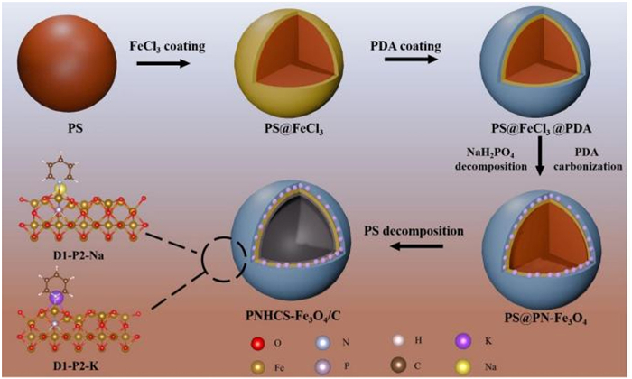
Figure 1.
Illustration of the fabrication procedure of the PNHCS-Fe3O4@C composite.

P-doped and N-adsorped hollow core-shell Fe3O4@carbon composite as an anode material for high-performance sodium/potassium-ion batteries
Yuan Jin , Junyuan Song , Chunquan Wu , Guangli Li , Yirong Zhu


Lithium-ion batteries have the advantages of high specific energy and long cycle life, and have been widely used in electric vehicles, consumer electronics and other fields [1]. Due to the limited reserves and uneven distribution of lithium resources in the crust, the sustainable development and large-scale application of lithium-ion battery technology face significant challenges, thereby limiting its deployment in large-scale energy storage and power systems [2,3]. Consequently, there is an urgent need to develop alternative secondary battery systems that can replace lithium-ion batteries. Sodium and potassium, which belong to the same main group as lithium, exhibit similar chemical properties and are abundant in reserves. Therefore, sodium/potassium-ion batteries are considered to be highly promising for low-cost and large-scale energy storage applications [4,5]. However, the larger ionic radii of sodium and potassium ions result in more pronounced volume changes in electrode materials and reduced kinetic performance, posing substantial challenges to the development of sodium/potassium-ion batteries [6,7]. Furthermore, the relatively low specific capacity and energy density of sodium/potassium-ion batteries present a significant challenge. Therefore, the development of high-performance anode materials is considered to be one of the most effective strategies to enhance the energy density of sodium/potassium-ion batteries [8,9].
As a typical class of anode materials for sodium/potassium ion-batteries, transition metal oxides primarily rely on conversion reactions for sodium/potassium-ion storage. During the discharging process, the formation of an amorphous structure leads to significant volume expansion due to its loose nature. Conversely, during the charging process, the amorphous metal elements recombine with Na2O/K2O to form corresponding metal oxides, releasing the Na+/K+ and thereby reducing the volume [10,11]. During the cycling processes, the electrode undergoes repeated volume changes. These continuous and significant volume fluctuations severely impact the cycle performance of transition metal oxide anodes. First, the initially formed solid electrolyte interphase (SEI) is prone to degradation during the volume expansion process, which causes the consumption of additional Na+/K+ for the formation of new SEI films, resulting in a rapid decline in reversible capacity and excessive electrolyte depletion [12,13]. Secondly, traditional electrodes predominantly utilize nano powders as active materials, which exhibit high surface energy [14]. During the charge-discharge process, the significant volume changes of transition metal oxides accelerate the agglomeration and pulverization, which leads to reduced activity and structural damage, thereby adversely affecting their cycle performance. Volume changes during charge/discharge cycles induce internal deformation stress within electrodes, damaging binder integrity and adhesion. Simultaneously, transition metal oxides suffer from sluggish ion transport kinetics under high current densities, leading to significant transport barriers and deteriorated rate capability. These factors collectively cause the pulverization, detachment, and rapid capacity fading of active materials [15]. Literature reports that a carbon-layer stress-buffering model with P-doping is utilized to enhance the interfacial toughness for mitigating volumetric strain [16]. Concurrently, based on the theory of ion transport kinetics, DFT calculations confirm that N adsorption sites effectively reduce the Na+/K+ diffusion barrier [17]. This establishes the complete theoretical logic chain: "volumetric stress - kinetic limitations → P/N Co-modification → performance enhancement". The primary reason is that transition metal oxides are predominantly semiconductor materials, exhibiting poor electrical conductivity and slow electron transport. During the discharge process, the formation of amorphous sodium oxide/potassium oxide further diminishes the conductivity [18,19]. Additionally, the SEI film generated during the charge-discharge reactions acts as an electronic insulator, coating the surface of the nanopowders and thereby reducing the overall conductivity of the electrode material. Both ion migration and electron transport influence the reaction rate, thereby affecting the charge-discharge performance at high current densities [20,21]. Consequently, as a critical component of sodium/potassium-ion batteries, it is imperative to develop low-cost anode materials with enhanced rate capability, capacity, and cycle life.
Iron-based materials have been extensively investigated as an anode material for sodium-ion batteries due to its abundant resources and low cost [22]. The current researches on iron-based anode materials primarily focus on iron oxides, sulfides, phosphates, and selenides, which predominantly undergo conversion reactions during the charge-discharge process [23,24]. Iron oxides (Fe2O3, Fe3O4) exhibit several advantages over other transition metal oxides. They possess the advantages of a high theoretical specific capacity (800~1000 mAh/g), low raw material cost, environmental friendliness, and non-polluting properties. Notably, Fe3O4 naturally exists in the form of magnetite and possesses a theoretical sodium storage capacity of up to 924 mAh/g [25,26]. However, Fe3O4 exhibits low intrinsic conductivity and undergoes significant volume expansion during the charging and discharging processes. This phenomenon adversely affects both cycling stability and rate performance. To address the aforementioned challenges, the performance can be enhanced through the integration of conductive materials and the reduction of nanoparticle dimensions [27]. The design of a nano-porous structure not only shortens the transport path of sodium ions, but also mitigates the severe strain induced by the volume changes in the anode during cycling. Moreover, it also facilitates the infiltration electrolyte into the material, thereby ensuring the adequate contact area between the electrolyte and electrode and enhancing the charge transfer at the electrode/electrolyte interface [28]. Additionally, the incorporation of heteroatoms (such as N, S, P, and B) can significantly enhance the reactivity, intrinsic electronic conductivity, and sodium ion diffusion coefficient of the material [29,30]. Currently, a growing number of researches indicate that the type of nitrogen doping is the predominant factor influencing the electrochemical properties of the material. In comparison to graphite-N and pyrrole-N, pyridine-N can introduce a greater number of effective active sites within the carbon framework and exhibit enhanced binding affinity towards alkali metal ions [31,32]. Therefore, a material with high specific surface area, abundant pore defects, and sufficient pore edges will provide the necessary prerequisites for the formation of a higher content of pyridine-N, thereby leading to more significant enhancement in electrochemical properties [33,34].
To address the aforementioned challenges, an innovative approach is proposed in this study through integrating high-capacity and cost-effective iron-based transition metal compounds (Fe3O4) with highly conductive and stable carbon materials. Through structural optimization and phosphorus doping, the pyridine nitrogen content in nitrogen-doped materials is modulated to achieve a significantly enhanced level of pyridine nitrogen doping. Combining with experimental characterizations and theoretical calculations, the electrochemical performance of P-doped and N-adsorbed hollow core-shell Fe3O4@carbon composite (PNHCS-Fe3O4@C) as an anode material for sodium/potassium-ion batteries was systematically investigated.When utilized as an anode material for sodium-ion batteries, the PNHCS-Fe3O4@C electrode demonstrates a high reversible specific capacity of 256.7 mAh/g at 10,000 mA/g and the capacity retention is almost 100% after a high-rate cycle at 5000 mA/g. When employed as an anode material for potassium-ion batteries, the PNHCS-Fe3O4@C electrode achieves a specific capacity of 116.7 mAh/g at 10,000 mA/g and the capacity retention is nearly 100% after a high-rate cycle at 1000 mA/g. This work not only addresses the intrinsic issues of low conductivity and significant volume expansion in Fe3O4-based materials, but also pioneers a new avenue for developing high-rate and stable cathodes, thereby facilitating the large-scale application of high-power and long-duration sodium/potassium-ion batteries.
The synthesis process of the PNHCS-Fe3O4@C composite with a hollow core-shell structure is illustrated in Fig. 1. Initially, the polystyrene (PS) microspheres with a diameter of approximately 100 nm were used as templates. Through a polymerization reaction, FeCl3 was uniformly deposited on the surface of these PS microspheres, forming a core-shell structured PS@FeCl3. Subsequently, PDA was evenly coated onto the surface of the PS@FeCl3 microspheres via another polymerization reaction, resulting in the formation of a core-shell structure designated as PS@FeCl3@PDA. During the calcination process, NaH2PO2 begins to decompose into PH3 gas at temperatures below 300 ℃. Simultaneously, the PDA coating initiates carbonization and phosphorus doping [35,36]. As the calcination temperature increases, the PS microspheres decompose around 400 ℃, resulting in the formation of the PNHCS-Fe3O4@C composite. For comparison, the NHCS-Fe3O4@C composite with only nitrogen adsorption and the HCS-Fe3O4@C composite without nitrogen adsorption or phosphorus doping were synthesized. The detailed synthesis procedures are outlined in the experimental section.
Scanning electron microscopy (SEM) analysis systematically reveals the different morphological evolutions of the HCS-Fe3O4@C, NHCS-Fe3O4@C, and PNHCS-Fe3O4@C composites (Figs. 2a-c and Figs. S1a-c in Supporting information). The HCS-Fe3O4@C composite exhibits well-defined nanospheres with highly uniform particle sizes centered at approximately 200 nm (Fig. 2a and Fig. S1a), demonstrating superior structural regularity. The NHCS-Fe3O4@C composite maintains spherical geometry but with enlarged particle sizes (~300 nm), accompanied by a unique sea urchin-like surface texture (Fig. 2b and Fig. S1b), which indicates surface coarsening induced by nitrogen doping. The incorporation of nitrogen can achieve controllable preparation of nano-scale spherical materials through precisely altering the decomposition and carbonization processes of the PS microspheres. Specifically, PDA releases gases such as NH3 and HCN during carbonization, thereby substantially increasing the porosity within the carbon layer. To facilitate the escape of these gases, the carbon shell undergoes outward expansion, ultimately resulting in an increase in particle sizes from 200 nm to 300 nm. The PNHCS-Fe3O4@C composite preserves the 300 nm spherical framework after phosphorus doping (Fig. 2c and Fig. S1c), confirming the structural stability of the nitrogen-rich matrix during heteroatom incorporation.
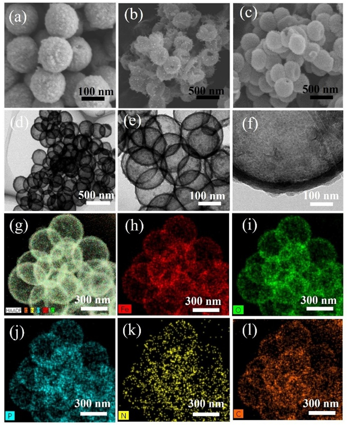
Transmission electron microscopy (TEM) further elucidates the hierarchical architecture of the PNHCS-Fe3O4@C composite (Figs. 2d-f), where Fe3O4 nanoparticles (< 10 nm) are homogeneously encapsulated within a hollow amorphous carbon shell (~20 nm thickness). This core-shell configuration effectively buffers the volume expansion while ensuring the electrical connectivity. EDS elemental mapping (Figs. 2g-l) conclusively verifies the spatial homogeneity of Fe, O, N, C, and P elements throughout the PNHCS-Fe3O4@C composite. The uniform distribution of the Fe and O elements indicates that the Fe3O4 nanoparticles are well dispersed in the carbon matrix without agglomeration, significantly improving its cycling stability. The continuous distribution of the C element verifies the complete coating of the carbon shell, and the three-dimensional conductive network constructed by it provides a guarantee for the fast transport of electrons. The uniform adsorption and doping of N and P optimize the electronic structure and facilitate the transport of sodium and potassium ions.
The X-ray diffraction (XRD) patterns in Fig. 3a unambiguously confirm the crystalline phase evolution of the HCS-Fe3O4@C, NHCS-Fe3O4@C, and PNHCS-Fe3O4@C composites. All samples exhibit the characteristic diffraction peaks indexed to the cubic magnetite structure (space group: Fd-3 m), with peak positions aligning precisely with the standard Fe3O4 reference (JCPDS No. 89–0691) [37]. Compared to HCS-Fe3O4, the X-ray diffraction peak of the (220) crystal plane of the PNHCS- Fe3O4@C and NHCS-Fe3O4@C composites exhibit a notable increase in half-height width (FWHM) (Fig. S2 in Supporting information). This phenomenon is primarily ascribed to the formation of physical or chemical coating layers on the surface of Fe3O4 particles by porous nitrogen-adsorbed and phosphorus-doped carbon shells. These layers impede grain growth during high-temperature treatment or reaction, leading to a substantial broadening of the (220) peak. These observations are attributed to the P-induced lattice distortion. Phosphorus doping introduces substitutional defects (P occupies the O site in Fe3O4), which perturbs the Fe-O-Fe bond network [37].
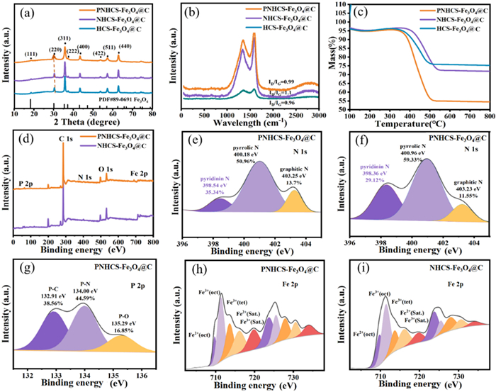
The Raman spectra of the PNHCS-Fe3O4@C and NHCS-Fe3O4@C composites exhibit characteristic D-band and G-band peaks at 1333 and 1559 cm-1, respectively. The D-band is indicative of disordered carbon structures, while the G-band is associated with the symmetry and crystallinity of sp2-hybridized carbon (Fig. 3b). The PNHCS-Fe3O4@C and NHCS-Fe3O4@C composites exhibit a higher band intensity ratio (ID:IG) compared with the HCS-Fe3O4@C composite, suggesting that the morphological and structural design introduce a greater number of defects [38]. TGA curves of the NHCS-Fe3O4@C and PNHCS-Fe3O4@C composites reveal that NaH2PO2 begins to decompose around 350 ℃ during calcination, releasing PH3 gas (Fig. 3c). Concurrently, the polydopamine (PDA) coating initiates carbonization and phosphorus doping. Subsequently, the PS microspheres undergo carbonization and decomposition at approximately 400 ℃, ultimately forming a hollow core-shell structure.
To further investigate the bonding characteristics of the PNHCS-Fe3O4@C and NHCS-Fe3O4@C composites with different doping modes, X-ray photoelectron spectroscopy (XPS) analyses were conducted. The XPS spectra of the PNHCS-Fe3O4@C and NHCS-Fe3O4@C composites exhibit similar peaks for Fe, C, N, and O elements, except for an additional P 2p peak observed in the PNHCS-Fe3O4@C composite (Figs. 3d-i). Notably, the P 2p XPS spectrum of the PNHCS-Fe3O4@C composite confirms the presence of P-C (132.91 eV), P-N (134.00 eV), and P-O (135.29 eV) bonds, among which the P-N bond is the predominant phase. These results indicate that the P atom primarily replaces the oxygen atom adsorbed by N within the Fe3O4@C framework, and subsequently forms a bond with the N atom [39,40]. Three distinct nitrogen peaks are observed in the PNHCS-Fe3O4@C and NHCS-Fe3O4@C composites, specifically pyridine-N, pyrrole-N, and graphite-N. Notably, the pyridine-N content in the PNHCS-Fe3O4@C composite increases from 29.12% to 35.34% after phosphorus doping. It is noteworthy that the NHCS-Fe3O4@C composite with a hollow core-shell structure exhibits a high initial pyridine-N content, which further significantly increases with the increase of phosphorus doping. Consequently, it can be inferred that the three-dimensional porous structure with a hollow core-shell architecture may provide favorable conditions for the formation of elevated levels of pyridine-N. Experimental results indicate that the formation of the P-N bond may alter the electronic structure, leading to the changes in N-adsorbed configurations and the creation of additional defects, thereby promoting a higher proportion of pyridine-N. It has been reported that an increase in pyridine-N content correlates with improved sodium and potassium storage properties of the PNHCS-Fe3O4@C and NHCS-Fe3O4@C composites [41,42]. This is attributed to the high reactivity of pyridine-N, which induces a greater number of active sites compared to other nitrogen configurations [43,44]. In our study, a high pyridine-N content was achieved through additional phosphorus doping rather than by reducing the sintering temperature. This approach successfully prevents the degradation of electronic conductivity, thereby enhancing the sodium and potassium storage properties of the PNHS-Fe3O4@C composite.
Fig. S3 (Supporting information) illustrates the specific surface area and pore size distribution of the PNHCS-Fe3O4@C composite. As demonstrated in Fig. S3, the PNHCS-Fe3O4@C composite is quantitatively resolved through N2 adsorption-desorption isotherms, exhibiting a pronounced hysteresis loop at P/P0 = 0.45–0.95, which is characteristic of a Type IV isotherm with H3-type hysteresis, a signature of mesoporous structures formed by the stacking of platelet-like particles. The Brunauer-Emmett-Teller (BET) specific surface area is high up to 106.8 m2/g, while the Barrett-Joyner-Halenda (BJH) analysis reveals a large pore volume of 0.14 cm3/g with a dominant pore size distribution centered at 3–5 nm. The large specific surface area establishes an extensive electrochemically active interface between Fe3O4 and the carbon matrix, significantly enhancing the adsorption capability for Na+ [43]. Simultaneously, the three-dimensional interconnected mesoporous network with primary pore sizes of 3–5 nm functions as a rapid ion transport channel, effectively minimizing the ion diffusion resistance [44,45]. Furthermore, the strategically engineered macropores provide a mechanical buffer, accommodating the volume expansion of Fe3O4 during repeated intercalation/deintercalation cycles.
An in-depth investigation into the sodium storage properties of the PNHCS-Fe3O4@C composite was carried out (Fig. 4). Cyclic voltammetry (CV) curve of the PNHCS-Fe3O4@C electrode was measured at 10 mV/s in the voltage range of 0.01–3.0 V (vs. Na+/Na). As illustrated in Fig. 4a, the PNHCS-Fe3O4@C electrode exhibits a characteristic CV profile typical of Fe3O4. The CV curve displays prominent anodic and cathodic peaks associated with iron oxide, which is indicative of a reversible Faradaic reaction between Fe3+ and Fe2+. The rate performance further confirms the superior sodium storage capability of the PNHCS-Fe3O4@C electrode compared with the NHCS-Fe3O4@C and HCS-Fe3O4@C electrodes (Fig. 4b and Fig. S4 in Supporting information). Specifically, the specific discharge capacities of the PNHCS-Fe3O4@C electrode at current densities of 50, 100, 200, 500, 1000, and 2000 mA/g are 570.9, 505.3, 477.6, 425.6, 402.6, and 370.1 mAh/g, respectively. Notably, even at extremely high current densities of 5000 and 10,000 mA/g, the specific discharge capacities still remain as high as 305.6 and 256.7 mAh/g, respectively. When the current density returns to 50 mA/g, the specific discharge capacity recovers to 570.5 mAh/g, indicating that the PNHCS-Fe3O4@C electrode exhibits outstanding electrochemical reversibility and cycling stability. It is notable that the specific discharge capacity of the PNHCS-Fe3O4@C electrode at current densities of 50 mA/g and 10,000 mA/g is 1.3 and 7.3 times higher than that of the NHCS-Fe3O4@C electrode, respectively, validating its exceptional rate performance.
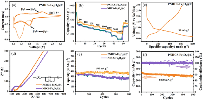
Fig. 4c displays the initial charge/discharge profile of PNHCS-Fe3O4@C at 50 mA/g, delivering an initial reversible capacity of 602.4 mAh/g with distinct voltage plateaus at ~0.8 V (reduction) and ~1.8 V (oxidation). The characteristic redox peaks in CV curves (Fig. 4a) correspond to these voltage plateaus, collectively verifying the high reversibility of Na+ storage kinetics. Notably, the specific discharge capacity and first-cycle coulombic efficiency of the PNHCS-Fe3O4@C electrode are markedly enhanced due to the increased content of active pyridine nitrogen and the rational design of the hollow core-shell structure, which provides numerous active sites for surface charge transfer and Na+ adsorption [46–48]. EIS spectra (Fig. 4d) indicate that the charge transfer resistance and sodium ion diffusion resistance of the PNHCS-Fe3O4@C electrode are substantially reduced, suggesting that the hollow core-shell structural design and higher content of active pyridine nitrogen improve the electronic conductivity and facilitate the sodium ion diffusion [49].
Fig. 4e illustrates the cycling performance of the PNHCS-Fe3O4@C and NHCS-Fe3O4@C composites at a current density of 500 mA/g. During the initial cycles, both electrodes exhibit a certain decline in specific discharge capacity, which is primarily attributed to the instability of the SEI film and irreversible sodium insertion during the early stages of cycling. After more than 10 cycles, the PNHCS-Fe3O4@C and NHCS-Fe3O4@C electrodes demonstrate outstanding cyclic stability. After 800 cycles, the specific discharge capacities of the PNHCS-Fe3O4@C and NHCS-Fe3O4@C electrodes are 350.7 and 250.8 mAh/g, respectively. The long-term cycling stability of the PNHCS-Fe3O4@C electrode at a high current density of 5000 mA/g further corroborates its exceptional electrochemical performance. As illustrated in Fig. 4f, the specific discharge capacity of the PNHCS-Fe3O4@C electrode remains as high as 290.4 mAh/g after 500 cycles with a capacity retention approaching 100%. After 500 cycles, the morphology of the PNHCS-Fe3O4@C electrode is well-preserved (Fig. S5 in Supporting information). The results show that the hollow core-shell structure significantly improves the cycle stability. The spatial limiting effect of the hollow core-shell structure effectively inhibits the agglomeration of Fe3O4 nanoparticles, which prevents the deactivation of active materials during cycling. N adsorption and P doping induce the interfacial charge reconstruction to optimize the ion transport path. The hierarchical pore structure alleviates the volume expansion of the electrode material during intercalation/deintercalation through the design of the stress buffer layer. The triple stabilization strategy of structure confinement, charge regulation, and stress dissipation enables the electrode to achieve a capacity retention of nearly 100% after 500 cycles at a high current density of 5000 mA/g, providing a new paradigm for the design of highly stable energy storage materials. Table S1 (Supporting information) systematically compare the sodium-ion storage performance of PNHCS-Fe3O4@C with recently reported transition metal oxide anodes over the last five years, clearly demonstrating the unique advantages and significant advancements in this study. In summary, the hollow core-shell structure (HCS-Fe3O4@C) significantly enhances the intrinsic electrochemical properties (1.9 times that of pure Fe3O4), but fails to address kinetic limitations; N adsorption (NHCS-Fe3O4@C) further improves ion diffusion (capacity retention increased to 71.6%); P-N co-modification (PNHCS-Fe3O4@C) achieves synergistic enhancement in structural stability and kinetics optimization by increasing the content of pyridinic-N (35.34% vs. 0% in HCS-Fe3O4@C) and reducing the adsorption energy (ΔE = −0.273 eV). The hollow core-shell structure provides structural stability through the elastic strain adjustment of the engineering cavity and is synergistically integrated with the dynamic optimization of N/P co-modification, therefore achieving significantly enhanced electrochemical properties.
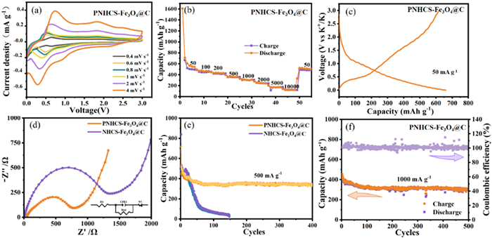
Based on the synergistic advantages of the PNHCS-Fe3O4@C composite in sodium storage through hollow core-shell structure design and N adsorption/P doping strategy, this study further investigated and validated its applicability in potassium-ion batteries. CV curves (Fig. 5a) were investigated at various scan rates within the voltage range of 0.01–3.0 V (vs. K/K+). As the scan rate increases from 0.4 mV/s to 4 mV/s, the characteristic peaks exhibit a high degree of symmetry. Rate performance further confirms the superior potassium storage capability of the PNHCS-Fe3O4@C electrode compared with the HCS-Fe3O4@C electrode (Fig. 5b and Fig. S6 in Supporting information). The specific discharge capacities of the PNHCS-Fe3O4@C electrode at current densities of 50, 100, 200, 500, 1000, and 2000 mA/g are 500.9, 477.6, 400.6, 370.6, 320.1, and 300.5 mAh/g, respectively (Fig. 5b). Even at ultrahigh current densities of 5000 and 10,000 mA/g, the specific discharge capacities of the PNHCS-Fe3O4@C electrode are still as high as 200.6 and 116.7 mAh/g, respectively. When the current density returns to 50 mA/g, its specific capacity recovers to 496.5 mAh/g, validating its superior electrochemical reversibility and cyclic property. Fig. 5c presents the initial GCD curve of the PNHCS-Fe3O4@C electrode at 500 mA/g. The first irreversible capacity loss is mainly due to the formation of the SEI film, which is a common phenomenon in metal oxide. EIS spectra (Fig. 5d and Fig. S7 in Supporting information) indicate that the charge transfer resistance and potassium ion diffusion resistance of the PNHCS-Fe3O4@C electrode are substantially reduced compared to the NHCS-Fe3O4@C electrode. The results demonstrate that the hollow core-shell structural design, coupled with a higher content of active pyridine nitrogen, enhances the electronic conductivity and facilitates the diffusion of potassium ions. Fig. 5e illustrates the cycling performance of the PNHCS-Fe3O4@C and the NHCS-Fe3O4@C electrode at a current density of 500 mA/g. After more than 10 cycles, the PNHCS-Fe3O4@C electrode demonstrates excellent cyclic stability, whereas the capacity of NHCS-Fe3O4@C electrode drops sharply. After 400 cycles, the specific discharge capacity of the PNHS-Fe3O4@C electrode remains at 375.7 mAh/g. Long-term cycling stability at 1000 mA/g further corroborates its outstanding cycle performance. As shown in Fig. 5f, the specific capacity remains as high as 300.4 mAh/g with nearly 100% capacity retention after 500 cycles. Table S2 (Supporting information) systematically compares the potassium-ion storage performance of PNHCS-Fe3O4@C with recently reported transition metal oxide anodes over the last five years. This work further elucidates the exceptional properties of the PNHCS-Fe3O4@C electrode in potassium-ion batteries, leveraging the strategy of hollow core-shell confinement and N adsorption/P doping coordination. Specifically, its hierarchical pore structure optimizes the K+ diffusion pathway. The N absorption/P doping effectively reduces the charge transfer resistance, while the mechanical buffering effect of the hollow core-shell structure ensures superior long-term cycling stability.
To investigate the impact of nitrogen-adsorbed configurations and phosphorus doping on the electronic properties and K+/Na+ adsorption capability of PNHS-Fe3O4@C, density functional theory (DFT) calculations were conducted. Pyrrolidine and pyridinium can be adsorbed on Fe atoms of Fe3O4 (220) (Fig. S8a in Supporting information). The Fe sites are designated as Fe1 and Fe2 (Fig. S8b in Supporting information). When pyridine nitrogen is adsorbed on Fe1/Fe2, the systems are named D1/D2, respectively (Figs. 6a and b). Similarly, when pyrrole nitrogen is adsorbed on Fe1/Fe2, the systems are named L1/L2, respectively (Figs. 6c and d). DFT calculations were used to determine the adsorption energies of pyridine nitrogen and pyrrole nitrogen at different Fe sites, and the results are presented in Fig. 6m and Table S3. According to Fig. 6m and Table S3, the adsorption energy of D1 is lower than that of D2, indicating that pyridine nitrogen preferentially adsorbs on Fe1. Conversely, the adsorption energy of L2 is lower than that of L1, suggesting that pyrrole nitrogen preferentially adsorbs on Fe2. Notably, L2 exhibits the lowest adsorption energy among all systems, implying that pyrrole nitrogen is more readily adsorbed compared to pyridine nitrogen and is the most likely adsorbed molecule. Further, P doping in the optimal pyridine-N-adsorbed and pyrrole-N-adsorbed structures reveals two distinct doping sites, O1 and O2 (Fig. S8c in Supporting information). When P doping occurs at the O1/O2 site on D1, the systems are named D1-P1/D1-P2, respectively (Figs. 6e and f). Similarly, when P doping occurs at the O1/O2 site on L2, the systems are named L2-P1/L2-P2, respectively (Figs. 6g and h). The crystal structures of Na/K adsorption system are shown in Figs. 6i-l.
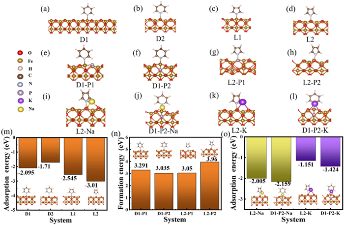
The calculated formation energy and adsorption energy for each system are summarized in Figs. 6m-o and Tables S4 and S5 (Supporting information). These results indicate that D1-P2 has the lowest formation energy after P doping, suggesting that P doping renders the adsorption structure of pyridine nitrogen the most thermodynamically stable. This change leads to a significant increase in the content of pyridine nitrogen, which is consistent with experimental findings. Additionally, the adsorption energies of Na and K ions on the optimal structures (both P-doping and undoping) were further calculated, and the results are presented in Table S6 (Supporting information). DFT calculations reveal that phosphorus doping reduces the adsorption energy of Na+/K+ by 0.154/0.273 eV compared to undoped Na+/K+, indicating improved interfacial binding affinity via charge redistribution on the Fe3O4/C heterojunction. This enhanced interaction probably arises from the increase in pyridine-N content to 35.34%, where its lone-pair electrons form strong coordination bonds with the empty orbitals of Na+/K+, thereby decreasing the adsorption energy ΔE [50,51]. Additionally, pyridine-N and phosphorus atoms act as electron donors, creating local negative-charge regions in the carbon layer, further enhancing the coulombic attraction to Na+/K+ [52,53]. Computational studies based on DFT demonstrate that the synergistic effect of nitrogen adsorption and phosphorus doping significantly improves the electrochemical performance of the PNHS-Fe3O4@C electrode. This enhancement is achieved by reducing the adsorption energy of Na+/K+ and accelerating the charge transfer kinetics. This bifunctional modification strategy not only establishes a robust theoretical framework but also provides a practical paradigm for designing highly stable anode materials for sodium/potassium-ion batteries.
In summary, the P-doped and N-adsorbed hollow core-shell Fe3O4@C composite (PNHCS-Fe3O4@C) has been successfully synthesized through a template-assisted method combined with gas-phase phosphating treatment, which is innovatively applied as an anode for high-performance sodium/potassium-ion batteries for the first time. Benefiting from the synergistic effect of hollow core-shell structure design and N adsorption/P doping co-modification strategy, the PNHCS-Fe3O4@C electrode demonstrates remarkable advantages: The hollow core-shell structure effectively suppresses the volume expansion via physical constraints, and the N adsorption/P doping co-modification strategy synergistically reduces Na+/K+ adsorption energy and enhances the interfacial charge transport. Electrochemical results show that the PNHCS-Fe3O4@C electrode in sodium-ion batteries delivers a high reversible specific capacity of 256.7 mAh/g at 10,000 mA/g and outstanding cycling stability with approximately 100% capacity retention after 500 cycles at 5000 mA/g. More impressively, the PNHS-Fe3O4@C electrode in potassium-ion batteries achieves a high specific capacity of 116.7 mAh/g at 10,000 mA/g and exceptional cycling stability with nearly 100% capacity retention after 500 cycles at 1000 mA/g. Systematic DFT calculations reveal that N adsorption/P doping decreases the Na+/K+ adsorption energy by 0.154/0.273 eV compared to the undoped system, substantially accelerating the charge transfer kinetics and thereby achieving a substantial enhancement in electrochemical performance. The proposed synergistic modification strategy not only establishes a novel paradigm for designing stable alkali-ion battery anodes but also provides a universal framework extendable to multivalent ion systems, demonstrating both theoretical innovation and scalable engineering potential.
Yuan Jin: Writing – original draft, Formal analysis, Data curation. Junyuan Song: Investigation. Chunquan Wu: Software. Guangli Li: Writing – review & editing, Funding acquisition. Yirong Zhu: Writing – review & editing, Supervision, Resources, Project administration, Funding acquisition.
The authors declare that they have no known competing financial interests or personal relationships that could have appeared to influence the work reported in this paper.
The work is financially supported by Hunan Provincial and Municipal Joint Fund Project (No. 2020JJ6066), National Natural Science Foundation Project (No. 21601057) and General Project of Hunan Provincial Education Department (No. 24C0292).
Supplementary material associated with this article can be found, in the online version, at doi:
X. Lu, X. Zhang, Y. Zheng, et al., Proc. Natl. Acad. Sci. U. S. A. 119 (2022) e2122252119. doi: 10.1073/pnas.2122252119
W. Zhong, R. Zhao, Y. Zhu, et al., Adv. Funct. Mater. 35 (2025) 2419720. doi: 10.1002/adfm.202419720
Y. Zhu, R. Zhao, Y. Xu, et al., Adv. Mater. 37 (2025) 2419582. doi: 10.1002/adma.202419582
N. Wu, J. Shen, X. Zhou, et al., Adv. Energy Mater. 15 (2025) 2405729. doi: 10.1002/aenm.202405729
D. Hou, D. Xia, E. Gabriel, et al., ACS. Energy Lett. 11 (2021) 4023–4054. doi: 10.1021/acsenergylett.1c01868
C.J. Li, W.H. Yang, W. He, et al., Energy Storage Mater. 43 (2021) 19.
S. Niloofar, B. Amin, G. Lars, et al., Prog. Energy Combust. Sci. 87 (2021) 100929. doi: 10.1016/j.pecs.2021.100929
S.Y. Yang, V. Sencadas, S.S. You, et al., Adv. Funct. Mater. 44 (2021) 2009289.
Y. Zhang, J. Wang, Z. Xue, et al., Adv. Funct. Mater. 10 (2024) 2311925.
H. Ding, J. Zhou, A. Rao, et al., Natl. Sci. Rev. 9 (2021) 276.
R. Hossein, V. Johanna, S. Pekka, et al., Chem. Eng. J. 495 (2024) 153471. doi: 10.1016/j.cej.2024.153471
K. Aegyeom, B. Young-woon, J.Y. Wang, et al., Energy Storage Mater. 47 (2022) 112 -105.
I. Ivan, S. Konstantin, W.Y. Zhang, et al., Carbon 186 (2022) 63 -55.
X. Wu, C. Wang, J. Wang, et al., Chem. Eng. J. 491 (2024) 152060. doi: 10.1016/j.cej.2024.152060
T.Q. Guo, P.F. Hu, L.D. Li, et al., Joule 3 (2022) 587 -543.
N. Soltani, A. Bahrami, L. Giebeler, et al., Prog. Energy Combust. Sci. 87 (2021) 100929. doi: 10.1016/j.pecs.2021.100929
T. Li, D. Zhao, M. Shi, et al., J. Mater. Chem. A 11 (2023) 1461–1472. doi: 10.1039/d2ta08539a
T.Q. Guo, P.F. Hu, L.D. Li, et al., Chem 9 (2023) 1080–1093. doi: 10.1016/j.chempr.2023.03.032
W.Y. Jang, C.V. Reddy, R. Wang, et al., Chem. Eng. J. 476 (2023) 146786. doi: 10.1016/j.cej.2023.146786
T.Z. Hu, J. Li, Y.Z. Wang, et al., Joule 6 (2023) 1205 -1176.
Y. Lei, L.L. Xu, Q.N. Chan, et al., Transportation 20 (2024) 100330.
G. Ayat, M. Rabiei, S. Mehranfar, et al., Renew. Sust. Energy Rev. 202 (2024) 114654. doi: 10.1016/j.rser.2024.114654
D. Zhao, Y. Chen, Y. Liu, Chin. Chem. Lett. 26 (2015) 829–833. doi: 10.1016/j.cclet.2014.11.028
Y.H. Guo, Y.Y. Liu, J.P. Wan, Chin. Chem. Lett. 26 (2015) 829–833. doi: 10.1016/j.cclet.2014.11.028
Q.X. Xie, Y.F. Zhang, D.L. Xie, et al., J. Electroanal. Chem. 857 (2020) 113749. doi: 10.1016/j.jelechem.2019.113749
J. Wang, Q. Hu, W.H. Hu, et al., Molecules 2 (2022) 396.
Z.L. Xiu, J.Y. Ma, X. Wang, et al., J. Solid. State Chem. 282 (2020) 121118. doi: 10.1016/j.jssc.2019.121118
H.H. Bi, X.J. He, Y. Lei, et al., J. Energy Chem. 66 (2022) 195–204. doi: 10.1016/j.jechem.2021.08.016
H.S. Hou, L.D. Shao, Y. Zhang, et al., Adv. Sci. 1 (2016) 4.
X.Q. Xie, K. Kretschmer, J.Q. Zhang, et al., Nano Energ. 13 (2015) 208–217. doi: 10.1016/j.nanoen.2015.02.022
R.Q. Cheng, Y.L. Min, H.X. Li, et al., Nano Energ. 115 (2023) 108718. doi: 10.1016/j.nanoen.2023.108718
R.R. Natalia, S.G. Lucia, A. Ana, et al., Carbon 228 (2024) 119291. doi: 10.1016/j.carbon.2024.119291
R. Bahadur, G. Singh, M.Y. Li, et al., Chem. Eng. J. 460 (2023) 141793. doi: 10.1016/j.cej.2023.141793
R. Wang, W.Y. Jang, W. Zhang, et al., Chem. Eng. J. 472 (2023) 144913. doi: 10.1016/j.cej.2023.144913
J.Q. Yang, X.L. Zhou, D.H. Wu, et al., Adv. Mater. 6 (2016) 1604108.
G.Q. Zou, H.S. Hou, G.G. Zhao, et al., Green. Chem. 19 (2017) 4622–4632. doi: 10.1039/C7GC01942D
S.H. Teo, C.H. Ng, Y.H. Ng, et al., Nano Energ. 99 (2022) 107401. doi: 10.1016/j.nanoen.2022.107401
X.F. Zhu, D.T. Zhang, C.J. Chen, et al., Nano Energ. 71 (2020) 104597. doi: 10.1016/j.nanoen.2020.104597
X.Q. Wei, S.J. Song, W.W. Cai, et al., Chem 9 (2023) 181–197. doi: 10.1016/j.chempr.2022.10.001
M. Zhang, S. Muhammad, H.L. Fei, et al., Adv. Energy Mater. 37 (2019) 1901663.
J.W. Xu, Z.Y. Huang, H.H. Zhou, et al., Energy Storage Mater. 72 (2024) 103596. doi: 10.1016/j.ensm.2024.103596
B. Byambaa, E. Kim, M. Gashaw, et al., Chem. Eng. J. 456 (2023) 141037. doi: 10.1016/j.cej.2022.141037
M. Parsa, Y. Qi, J.D. Nuzzo, et al., Chem. Eng. J. 471 (2023) 144699. doi: 10.1016/j.cej.2023.144699
F. Wang, X.Y. Wen, U. Mittal, et al., Carbon 222 (2024) 119003. doi: 10.1016/j.carbon.2024.119003
L. Manjakkal, A. Jain, S. Nandy, et al., Chem. Eng. J. 465 (2023) 142845. doi: 10.1016/j.cej.2023.142845
Y. Jin, T.Y. Wang, G.L. Li, et al., Environ. Chem. Eng. 13 (2025) 115629. doi: 10.1016/j.jece.2025.115629
H. Zhang, X. Liu, T. Ji, et al., Chin. Chem. Lett. 37 (2026) 110790. doi: 10.1016/j.cclet.2024.110790
H. Yin, D. Han, W. Wang, et al., Chin. Chem. Lett. 36 (2025) 110537. doi: 10.1016/j.cclet.2024.110537
M. Zhang, X. Liu, J. Gu, et al., Chin. Chem. Lett. 34 (2023) 108471. doi: 10.1016/j.cclet.2023.108471
W.H. Feng, Y. Tan, M.F. Yang, et al., Chem 8 (2022) 351–383. doi: 10.1016/j.chempr.2021.11.010
J.W. Xu, Z.Y. Huang, H.H. Zhou, et al., Energy Storage Mater. 72 (2024) 103596. doi: 10.1016/j.ensm.2024.103596
N. Soltani, A. Bahrami, L. Giebeler, et al., Prog. Energy Combust. Sci. 87 (2021) 100929. doi: 10.1016/j.pecs.2021.100929
S. Wang, X. Zhang, S. Hao, Nano-Micro Lett. 1 (2023) 16.

Figure 2 SEM images of (a) the HCS-Fe3O4@C composite, (b) the NHCS-Fe3O4@C composite, and (c) the PNHCS-Fe3O4@C composite. (d-f) TEM images of the PNHCS-Fe3O4@C composite. (g-l) Elemental mapping images of the PNHCS-Fe3O4@C composite.

Figure 3 (a, b) XRD patterns and Raman spectra of the HCS-Fe3O4@C, NHCS-Fe3O4@C, and PNHCS-Fe3O4@C composites. (c) TGA curves of the HCS-Fe3O4@C, NHCS-Fe3O4@C, and PNHCS-Fe3O4@C composites. (d) XPS survey spectra of the PNHCS-Fe3O4@C and NHCS-Fe3O4@C composites. N 1s high-resolution XPS spectra of the (e) PNHCS-Fe3O4@C and (f) NHCS-Fe3O4@C composites. (g) P 2p high-resolution XPS spectrum of the PNHCS-Fe3O4@C composite. Fe 2p high-resolution XPS spectra of the (h) PNHCS-Fe3O4@C and (i) NHCS-Fe3O4@C composites.

Figure 4 Sodium storage performance of the PNHCS-Fe3O4@C and NHCS-Fe3O4@C composites. (a) CV curve of the PNHCS-Fe3O4@C electrode at 10 mV/s in the voltage range of 0.01–3.0 V (vs. Na+/Na). (b) Rate performance of the PNHCS- Fe3O4@C and NHCS-Fe3O4@C electrodes. (c) GCD curves of the PNHCS-Fe3O4@C electrode at 1000 mA/g in the voltage range of 0.01–3 V. (d) EIS spectra of the PNHCS-Fe3O4@C and NHCS-Fe3O4@C electrodes. (e) Cycling performance of the PNHCS-Fe3O4@C and NHCS-Fe3O4@C electrodes at 500 mA/g after 800 cycles. (f) Cycling performance of the PNHCS-Fe3O4@C electrode at 5000 mA/g after 500 cycles.

Figure 5 Potassium storage properties of the PNHCS-Fe3O4@C and NHCS-Fe3O4@C electrodes. (a) CV curves of the PNHCS-Fe3O4@C electrode at scan rates of 0.4–4 mV/s in the voltage range of 0.01-3.0 V (vs. K+/K). (b) Rate performance of the PNHCS-Fe3O4@C electrode. (c) GCD curve of the PNHCS-Fe3O4@C electrode at 500 mA/g. (d) EIS spectra of the PNHCS-Fe3O4@C and NHCS-Fe3O4@C electrodes. (e) Cycling performance of the PNHCS-Fe3O4@C and NHCS-Fe3O4@C electrodes at 500 mA/g. (f) Cycling performance of the PNHCS-Fe3O4@C electrode at 1000 mA/g after 500 cycles.

Figure 6 The crystal structure of (a) Fe3O4–220-D1 lateral view, (b) Fe3O4–220-D2 lateral view, (c) Fe3O4–220-L1 lateral view and (d) Fe3O4–220-L2 lateral view. (e-h) The crystal structure of P doping in N-adsorbed system. (i-l) The crystal structure of Na/K adsorption system. (m) The adsorption energy of pyridine nitrogen and pyrrole nitrogen at different Fe sites. (n) The formation energy of P doping in N-adsorbed system. (o) The Na/K adsorption energy of the optimal structure.

 扫一扫看文章


扫一扫关注我们
 DownLoad:

 下载:
 下载: