


Figure 1.
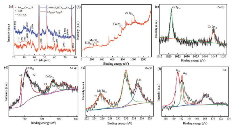
(a) XRD patterns of Zn—Co—S and CoMo2S4@Zn—Co—S composites, (b) XPS spectra of CoMo2S4@Zn—Co—S composites, (c) Zn 2p, (d) Co 2p, (e) Mo 3d, (f) S 2p.

With ever-increasing environmental pollution and the continuous deterioration for energy source shortage, it is very imperative to seek for new environmentally friendly and renewable energy [1-5]. Electrochemical capacitors (ECs), also called supercapacitors, have attracted tremendous interest due to their fast chargedischarge ability, high power density and long cycle life [6-10]. So, it is suitable for power-consuming devices with high-power output, such as electrical vehicles and various micro/nano-devices [11]. The performance of the ECs is highly dependent on their electrode materials. Many studies have focused on the rational design of appropriate electrodes to provide high capacity, long cycle stability, and high energy density [12-14].
In recent years, multi-element sulfides have caused great concern due to their large surface area, highly reactive redox reaction, and excellent crystalline characteristics [15-17], such as NiCo2S4 nanotube, CoNi2S4 mushroom-like arrays and NiCo2S4 nano-networks. Among them, the capacity of cobalt-containing sulfides is considerable. For example, the specific capacity of CoNi2S4 can reach 1250 F/g when the current density is 5 mA/cm2. In addition, mixed zinc-cobalt sulfides exhibit high specific capacitance and high conductivity owing to their rich redox reaction and high electronic conductivity [18-21]. For example, Zhang et al. reported the ZIFs-derived hollow bimetal (Zn, Co)S nanocrystals delivering specific capacitance (422.3 F/g at 10 mA/cm2). Li's group prepared Zn—Co—S nanowires as the advance electrodes with specific capacity of 366.7 mAh/g at a current density of 3 mA/cm2. However, single components electrode materials usually exhibit poor electrode stability and cycling life, which limit their further applications [22-24]. Hybrid-structured electrode materials can utilize the synergistic effects from two individual components. Therefore, to design hybrid electrodes with desiring spatial architectures is very important.
Herein, we reported a kind of novel CoMo2S4@Zn-Co-S nanostructures grown directly on Ni foam through a facile solution strategy. CoMo2S4 nanorods as the cores possess high capacity. However, the Zn—Co—S shells supply not only the effective path for electron transport but also additional capacity. Owning to the unique core-shell structures with more active sites, CoMo2S4@Zn—Co—S electrode materials present a high capacity of 4630 m F/cm2 at a current density of 1 mA/cm2 and good cycling stability with 85.6% capacity retention after 6000 cycles at current density of 10 mA/cm2. Furthermore, an asymmetric supercapacitor shows a volumetric energy density of 9.6 m Wh/cm3 at a volumetric power density of 235.471 m W/cm3. In the experiments, all of the reagents were analytical grade and used as purchased. Prior to the synthesis, a piece of Ni foam (3 × 3 cm2) was treated by immersed in 3 mol/L HCl solution for 30 min to remove the grease and oxidation film on the surface. Next, Ni foam was cleaned by sonication in ethanol and deionized water in sequence for 30 min and then dried for 12 h.
CoMoO4 nanorods were synthesized on Ni foam by a solvothermal route. In a typical synthesis process, 0.05 g CTAB was dissolved in 30 mL ethanol and 20 mL deionized water under continuously stirring 30 min. Then 0.17 g Co(NO3)2·6H2O and 0.55 g (NH4)6Mo7O24·4H2O were dissolved in the above solution. The solution was then transferred to 100 mL autoclave, and a piece of pretreated Ni foam was immersed in the reaction solution. The autoclave was sealed and maintained at 180 ℃ for 10 h and then cooled to room temperature. Then the as-synthesized products were dried at 60 ℃ for 10 h. The average mass loading is 1.6 mg/cm2. The as-synthesized CoMoO4 nanorods on Ni foam were immersed into the precursor solution of Zn—Co—O to prepare CoMo2O4@Zn—Co—O. Then CoMo2S4@Zn—Co—S was prepared by a one-step hydrothermal method. First, 0.35 g of Na2S was dissolved in 40 mL deionized water under continuously stirring of 30 min for forming a homogeneous solution, and then transferred to a 100 mL autoclave, and the prepared product was placed in the above solution and heated in an oven at 120 ℃ for 4 h, the product was taken out and rinsed with ethanol and deionized water, and dried at 60 ℃ for 12 h. The average mass loading is 2.8 mg/cm2.
The phase and crystallographic structure of the as-synthesized samples were measured by a powder X-ray diffraction analyzer (XRD, Shimadzu-7000) with Cu Kα radiation (λ = 1.5406 Å). The structure and morphology of the samples were characterized by using a scanning electron microscope (SEM, Hitachi-4800) and a high resolution transmission electron microscope (HRTEM, JEM- 2100 PLUS) operated at 200 kV. X-ray photoelectron spectra (XPS) measurements (ESCALAB250) were conducted to investigate the elemental composition using an Al Kα source.
The electrochemical characteristics of the as-synthesized products were performed by a CHI660E electrochemical workstation in a three-electrode system. The cyclic voltammetry (CV) curves, galvanostatic charge-discharge (GCD) and electrochemical impedance spectroscopy (EIS) measurements were obtained in 3 mol/L KOH aqueous electrolyte. The as-synthesized product was used directly as the working electrode. Pt foil served as the counter electrode and saturated calomel as the reference electrode. EIS measurements were conducted in a frequency range of 0.01 Hz to 100 kHz at a 10 mV open circuit potential. The specific capacitance and areal specific capacitance of the electrode were calculated from the GCD curve discharge process by following equations:
|
|
|
|
|
|
where Ca, I, t, S and V are the areal specific capacitance (C/cm2), the current density (mA/cm2), the discharging time (s), the active area of the electrode (cm2), and the discharging potential voltage range (Ⅴ), respectively.
Activated carbon was used as negative electrode material for asymmetric supercapacitor. The ratio of activated carbon, acetylene black, and polyvinylidene fluoride (PVDF) is 7:2:1, and a small amount of N-methylpyrrolidone is added. The above powder was uniformly ground in a mortar and then coated on Ni foam with the size of 1 cm in diameter. The as-synthesized CoMo2S4@Zn—Co—S product was used as the positive electrode. PVA-KOH gel was used as the electrolyte for asymmetric supercapacitor. 2 g PVA was dissolved in 15 mL deionized water with stirring at 80 ℃ for 30 min. At the same time, 2 g KOH was dissolved in 5 mL deionized water. After the above solutions were completely dissolved, KOH solution was added to PVA solution, which was vigorously stirred until the solution became uniform and clear. The positive and negative electrode were immersed in the above gel solution for 20 min and assembled.
The crystal structure of the as-synthesized samples is measured by XRD. The diffraction peak of Zn0.975Co0.025S sample is marked by a red triangle and the peak position can be found in Fig. 1a, the diffraction peaks at 2θ of 28.5°, 33.1°, 47.5, 59.1°, 69.4° and 79.1° in the pattern can be perfectly indexed to the (111), (200), (220), (222), (400) and (420) planes of cubic phase of Zn0.975Co0.025S (JCPDS No. 47-1655). At the same time, the characteristic peaks at 27.3°, 36.1°, 42.1°, 65.0°, 70.2° and 73.9° in the pattern can be indexed to (103), (013), (211), (008), (411) and (413) planes of cubic CoMo2S4 phase (JCPDs card No. 23-0192), respectively. In addition, the diffraction peak of CoMo2S4 also appeared in the XRD curve of the composite. The strongest peaks come from nickel foam. Ni2S is considered to be the vulcanization of Ni foam during the experiment. In addition, the poor intensity of the diffraction peaks demonstrates the poor crystallization of the as-synthesized samples, which is favorable for active material to get high capacitive properties [25, 26].
X-ray photoelectron spectroscopy (XPS) test is conducted to further analyze the surface chemical composition and chemical valence of different elements of the as-synthesized CoMo2S4@ ZnCo-S composites. Fig. 1b presents the XPS spectrum of CoMo2S4@Zn—Co—S composites. A full-survey-scan spectrum indicates the presence of Zn, Co, Mo, and S elements in the composites. Zn 2p spectrum is presented in Fig. 1c, in which two strong peaks at 1021.50 eV and 1044.50 eV correspond to the binding energy of Zn 2p3/2 and Zn 2p1/2, respectively, confirming the presence of Zn2+ in the composites. Fig. 1d shows the XPS spectrum of Co element, Co 2p spectrum could be decomposed into six components in the energy range of 772-810 eV. The peaks show low energy bands at 778.3 eV and 781.3 eV, which are assigned to the Co 2p3/2 and confirm the existence of a Co-S bond, The other double peaks at around 793.61 eV and 797.2 eV are related to the Co 2p1/2 from Co-O bond, which might originate from the surface oxidation in air [27]. Based on the wide peaks of Co 2p3/2 and Co 2p1/2, it is reasonable to assume that Co2+/Co3+ species co-existed in the composites. The XPS spectra of Mo 3d region (Fig. 1e) shows one distinct peak at the binding energy of 232.25 eV, corresponding to the Mo 3d3/2, which is attributed to Mo6+[28]. Fig. 1f shows the XPS spectrum of S element. Obviously, the composites are composed of Zn, S, Co and Mo elements.
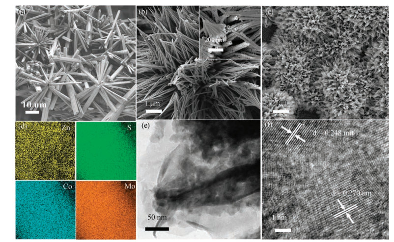
The morphology of the products are studied using SEM. Fig. 2a shows SEM image of the as-synthesized CoMo2S4 structure grown on Ni foam. Fig. 2b reveals hollow tubular morphology feature of Zn—Co—S and the outer diameter of the product ranges from between 30 nm and 50 nm. Fig. 2c exhibits high magnification SEM images of the as-synthesized product. Energy dispersive spectrometer (EDS) mappings (Fig. 2d) further prove the elemental composition of the composite material. The typical TEM image of the sample is shown in Fig. 2e. The outer shell structure with a thickness of 20 nm gives further evidence of the core-shell structure. HRTEM image in Fig. 2f indicates two distinct lattice spacings of 0.24 nm and 0.27 nm, which correspond to the (013) and (200) crystal plane of CoMo2S4 and Zn—Co—S sample, respectively.
The electrochemical performance of the as-synthesized electrode is studied by cyclic voltammetry (CV) and galvanostatic charge-discharge (GCD) measurements in 3 mol/L KOH aqueous solution. Fig. 3a shows the CV curves of CoMo2S4, Zn—Co—S and CoMo2S4@Zn—Co—S composites electrodes between a potential window of 0-0.8 V at a scan rate of 100 mV/s. The specific capacity of the composite material is significantly higher than that of Zn-CoS and CoMo2S4. Since the specific capacitance of the electrode is directly proportional to the area of the electrode [29], the CoMo2S4@Zn—Co—S electrode exhibits much larger charge storage capability that CoMo2S4 or Zn—Co—S. Fig. 3b presents CV curves of CoMo2S4@Zn—Co—S composite electrode at a scan rate of 5-100 mV/s. With the increase of scan rate, the curve area increases accordingly, while no significant change in the shape of CV curve is observed, demonstrating good rate capability of CoMo2S4@Zn—Co—S electrode. Fig. 3c shows GCD curves of CoMo2S4@Zn—Co—S composites at various current densities. Apparently, with the increase of current densities and the discharge time reduces. The charge and discharge time of the curves are approximately the same, indicating good reversibility of the composites. The CV and GCD curves of pristine CoMo2S4 and Zn—Co—S are shown in Figs. S1 and S2 (Supporting information), which further proves the excellent electrochemical performance of CoMo2S4@Zn—Co—S electrode. Fig. 3d exhibits the calculated specific capacitances of CoMo2S4, Zn—Co—S and CoMo2S4@Zn—Co—S composites at different current densities. The specific capacitance of CoMo2S4@Zn—Co—S composites is 2.793 C/cm2 at a current density of 1 mA/cm2, and still retains 1.79 C/cm2 when the current density increases 10 times. The capacitance retention from 1 mA/cm2 to 10 mA/cm2 for CoMo2S4@Zn—Co—S is 64%, indicating the excellent rate capability for CoMo2S4@Zn—Co—S composites. In contrast, the CoMo2S4 electrode shows capacitance performance of 2.76 C/cm2 at 1 mA/cm2 and poor rate capability of 1.41 C/cm2 at 10 mA/cm2, only 51% retention in comparison with that at 1 mA/cm2. The enhanced capacitance and remarkable rate capability of CoMo2S4@Zn—Co—S composites could be attributed to their unique core-shell structure. The shell consists of ultrafine Zn—Co—S nanotubes are beneficial to the electron enrichment, which can deliver high specific capacitance. Meanwhile, the highly conductive CoMo2S4 core can serve as the fast path for electron transport, which presents the good rate capability.
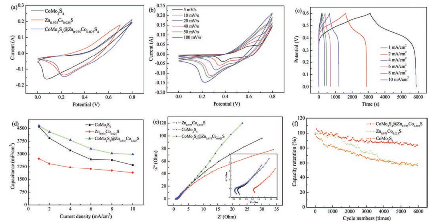
EIS measurements of the as-synthesized samples are carried out in the frequency range from 100 kHz to 0.01 Hz at the amplitude of 0.01 V, as shown in Fig. 3e. In the low frequency region, the slope of the line represents the diffusive resistance of the electrolyte ions [30]. The intersection with the horizontal axis represents bulk resistance (Rs), the diameter of semicircle shows the charge transfer resistance in high frequency region [31]. Obviously, the diameters of the three semicircles are roughly the same, but the slope of CoMo2S4@Zn—Co—S composites line is the largest. Therefore, the core-shell structure significantly reduces the diffusion resistance of the electrolyte ions. The long-term cycling performance is an important parameter for supercapacitor. The cycling stabilities of CoMo2S4, Zn—Co—S and CoMo2S4@Zn—Co—S composites are tested by continuous charge-discharge cycling at a high current density of 20 mA/cm2 for 6000 cycles. As shown in Fig. 3f, After 6000 cycles, the capacitance retention of CoMo2S4@Zn—Co—S composite is 85.6 %, which is much better than that of CoMo2S4 (59.1% capacitance retention after 6000 cycles) and Zn—Co—S (62% capacitance retention after 6000 cycles).
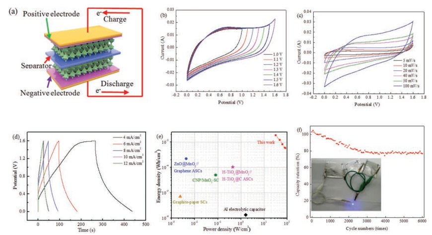
Based on CoMo2S4@Zn—Co—S composite as positive electrode) and ACs as negative electrode, an ASC is fabricated and its performance are shown in Fig. 4. Fig. 4a is schematic illustration of the as-assembled structure of CoMo2S4@Zn—Co—S //AC ASC. The CV curves for the CoMo2S4@Zn—Co—S//AC ASC at different voltage windows show that CoMo2S4@Zn—Co—S//AC ASC has a high operating cell voltage up to 1.6 V (Fig. 4b) and the curve is measured at the scan rate of 100 mV/s. Fig. 4c shows CV curves at different scan rates from 5 mV/s to 100 mV/s. With the sweep rate increasing, the shape of the curve remains unchanged, indicating the device possesses ideal capacitance performance. Fig. 4d indicates GCD curves at various current densities from 4 mA/cm2 to 12 mA/cm2. No obvious IR drop is observed in each discharge curve, implying the low internal resistance of the ASC [32]. In addition, all discharge curves are nearly symmetric to the corresponding charging counterparts, demonstrating the good electrochemical reversibility. The specific capacitance reaches a maximum of 0.84 C/cm2 at 4 mA/cm2. The energy densities and power densities of the as-prepared ASCs are shown in Fig. 4e. At a current density of 4 mA/cm2, the power density is 31.996 W/cm3 and the maximum energy density is 1.87 mWh/cm3. Compared with previously reported capacitive devices, the as-synthesized asymmetric supercapacitor exhibits superior electrochemical performance [33-37]. The long-term cycling stability of CoMo2S4@Zn—Co—S//AC ASC is examined by charge-discharge cycling at a current density of 10 mA/cm2. As shown in Fig. 4f, the capacitance retention of the ASC is 77% after 6000 cycles, which demonstrates excellent cycling stability. The inset in Fig. 4f shows the capacitor can light up a blue light. It can power a blue light indicator for 19 min (Fig. S3 in Supporting information), indicating its potential application in energy storage devices.
In summary, CoMo2S4@Zn—Co—S hybrids structures are successfully synthesized on Ni foam via a facile solvothermal route. The as-synthesized products can be used as electrode material for supercapacitor. It shows a high specific capacitance of 2.79 C/cm2 at current densities of 1 mA/cm2. 85.6% of its initial specific capacitance is remained after 6000 cycles. The quasi-solid-state asymmetric supercapacitor based on CoMo2S4@Zn—Co—S electrode material delivers a high energy density of 31.996 W/cm3 at a power density of 1.87 mWh/cm3. The specific capacitance of the ASC device shows 77% of capacitance retention, demonstrating potential application of the as-synthesized hybrid electrode materials in future energy storage devices.
This project is supported by State Key Laboratory of New Ceramic and Fine Processing Tsinghua University (No. KF201807).
Supplementary material related to this article can be found, in the online version, at doi:https://doi.org/10.1016/j.cclet.2018.11.019.
Y. Jiao, Y. Liu, B.S. Yin, et al., Nano Energy 10(2014) 90-98. doi: 10.1016/j.nanoen.2014.09.002
H. Yuan, L. Kong, T. Li, Q. Zhang, Chin. Chem. Lett. 28(2017) 2180-2194. doi: 10.1016/j.cclet.2017.11.038
X. Wu, S.Y. Yao, Nano Energy 42(2017) 143-150. doi: 10.1016/j.nanoen.2017.10.058
Y. Han, Q. Zhang, N.T. Hu, et al., Chin. Chem. Lett. 28(2017) 2269-2273. doi: 10.1016/j.cclet.2017.10.024
W. Jiang, F. Hu, Q.Y. Yan, X. Wu, Inorg. Chem. Front. 4(2017) 1642-1648. doi: 10.1039/C7QI00391A
H. Heydari, S.E. Moosavifard, M. Shahraki, S. Elyasi, J. Energy Chem. 26(2017) 762-767. doi: 10.1016/j.jechem.2017.03.007
W. Jiang, F. Hu, S.Y. Yao, Z.P. Sun, X. Wu, Mater. Res. Bullet. 93(2017) 303-309. doi: 10.1016/j.materresbull.2017.05.036
J.R. Miller, P. Simon, Science 321(2008) 651-652. doi: 10.1126/science.1158736
Z.G. Zhang, X. Huang, H. Li, et al., J. Energy Chem. 26(2017) 1260-1266. doi: 10.1016/j.jechem.2017.09.025
L. Xing, Y.D. Dong, F. Hu, X. Wu, A. Umar, Dalton Trans. 47(2018) 5687-5694. doi: 10.1039/C8DT00750K
K. Deori, S.K. Ujjain, R.K. Sharma, S. Deka, ACS Appl. Mater. Interfaces 5(2013) 10665-10672. doi: 10.1021/am4027482
C. Liu, W. Jiang, F. Hu, X. Wu, D.F. Xue, Inorg. Chem. Front. 5(2018) 835-843. doi: 10.1039/C8QI00010G
Q.F. Wang, X.F. Wang, J. Xu, et al., Nano Energy 8(2014) 44-51. doi: 10.1016/j.nanoen.2014.05.014
X. Wu, Z.C. Han, X. Zheng, et al., Nano Energy 31(2017) 410-417. doi: 10.1016/j.nanoen.2016.11.035
C. Liu, X. Wu, Mater. Res. Bullet. 103(2018) 55-62. doi: 10.1016/j.materresbull.2018.03.014
H.C. Chen, J.J. Jiang, L. Zhang, et al., J. Power Sour. 254(2014) 249-257. doi: 10.1016/j.jpowsour.2013.12.092
J. Pu, Z.H. Wang, K.L. Wu, N. Yu, E.H. Sheng, Phys. Chem. Chem. Phys. 16(2014) 785-791. doi: 10.1039/C3CP54192D
W. Cheng, C.L. Chen, Y. Yu, et al., Chin. J. Chem. 8(2017) 1303-1308. http://www.wanfangdata.com.cn/details/detail.do?_type=perio&id=CAS201303040000644931
C. Li, J. Balamurugan, N.H. Kim, J.H. Lee, Adv. Energy Mater. 8(2018) 1-12. http://www.wanfangdata.com.cn/details/detail.do?_type=perio&id=CAS201303040000644931
X.C. Xiao, G.F. Wang, M.M. Zhang, et al., Ionics 24(2018) 2435-2443. doi: 10.1007/s11581-017-2354-9
J. Wu, X.L. Shi, W. Song, et al., Nano Energy 45(2018) 439-447. doi: 10.1016/j.nanoen.2018.01.024
X. Zheng, Y. Jiao, F. Chai, et al., J. Colloid Interface Sci. 457(2015) 345-352. doi: 10.1016/j.jcis.2015.07.023
D.P. Zhao, F. Hu, A. Umar, X. Wu, New J. Chem. 42(2018) 7399-7406. doi: 10.1039/C8NJ00935J
J. Wang, X. Zhang, Q.L. Wei, et al., Nano Energy 19(2016) 222-234. doi: 10.1016/j.nanoen.2015.10.036
B.L. Ellis, P. Knauth, T. Djenizian, Adv. Mater. 26(2014) 3368-3397. doi: 10.1002/adma.v26.21
W. Hu, R.Q. Chen, W. Xie, et al., ACS Appl. Mater. Interfaces 6(2014) 19318-19326. doi: 10.1021/am5053784
L. Zheng, Y. Xu, D. Jin, Y. Xie, Chem.-Asian. J. 6(2011) 1505-1514. doi: 10.1002/asia.v6.6
J.M. Ko, D. Soundarajan, J.H. Park, et al., Curr. Appl. Phys. 12(2012) 341-345. doi: 10.1016/j.cap.2011.07.029
H. Yi, H.W. Wang, Y.T. Jing, T.Q. Peng, X.F. Wang, J. Power Sour. 285(2015) 281-290. doi: 10.1016/j.jpowsour.2015.03.106
M. Kim, Y.H. Wang, K. Min, J. Kim, Electrochim. Acta 113(2013) 322-331. doi: 10.1016/j.electacta.2013.09.058
J.X. Gou, S.L. Xie, Y.R. Liu, C.G. Liu, Electrochim. Acta 210(2016) 915-924. doi: 10.1016/j.electacta.2016.05.213
L.F. Shen, Q. Che, H.S. Li, X.G. Zhang, Adv. Funct. Mater. 24(2014) 2630-2637. doi: 10.1002/adfm.v24.18
M.F. El-Kady, V. Strong, S. Dubin, R.B. Kaner, Science 335(2012) 1326-1330. doi: 10.1126/science.1216744
L.Y. Yuan, B. Yao, B. Hu, et al., Energy Environ. Sci. 6(2013) 470-476. doi: 10.1039/c2ee23977a
L.Y. Yuan, X.H. Lu, X. Xiao, et al., ACS Nano 6(2012) 656-661. doi: 10.1021/nn2041279
Z.J. Fan, J. Yan, T. Wei, et al., Adv. Funct. Mater. 21(2011) 2366-2375. doi: 10.1002/adfm.v21.12
D.Z. Kong, C.W. Chen, Y. Wang, et al., J. Mater. Chem. A 3(2015) 16150-16161. doi: 10.1039/C5TA03469H

Figure 1 (a) XRD patterns of Zn—Co—S and CoMo2S4@Zn—Co—S composites, (b) XPS spectra of CoMo2S4@Zn—Co—S composites, (c) Zn 2p, (d) Co 2p, (e) Mo 3d, (f) S 2p.

Figure 2 (a) SEM images of CoMoO4 structure; (b) SEM images of Zn—Co—S structure; (c) SEM images of CoMo2S4@Zn—Co—S structure; (d) Elemental mapping images of Zn, S, Co, Mo; (e) TEM images of CoMo2S4@Zn—Co—S structure; (f) HRTEM image of CoMo2S4@Zn—Co—S structure.

Figure 3 (a) CV curves of CoMo2S4, Zn—Co—S and CoMo2S4@Zn—Co—S composites at a scan rate of 100 mV/s; (b) CV curves of CoMo2S4@Zn—Co—S composites at different scan rates; (c) GCD curves of CoMo2S4@Zn—Co—S composites at different current densities; (d) Specific capacitance of CoMo2S4, Zn—Co—S and CoMo2S4@Zn—Co—S composites at various current densities; (e) Nyquist plots of CoMo2S4, Zn—Co—S and CoMo2S4@Zn—Co—S composites; (f) Cycling performance of CoMo2S4, Zn—Co—S and CoMo2S4@Zn—Co—S composites.

Figure 4 (a) Schematic illustration of the as-assembled structure of CoMo2S4@Zn—Co—S//AC ASC; (b) CV curves of CoMo2S4@Zn—Co—S//AC ASC at different voltage windows; (c) CV curves of CoMo2S4@Zn—Co—S//AC ASC at different scan rates; (d) GCD curves of CoMo2S4@Zn—Co—S ASC at different densities; (e) Ragone plots of the device; (f) Cycling performance of CoMo2S4@Zn—Co—S//AC ASC at a current density of 10 mA/cm2, the inset shows the device can light up blue light.

 扫一扫看文章

扫一扫关注我们
 DownLoad:
 下载:
下载:
 下载:
下载: