 图1
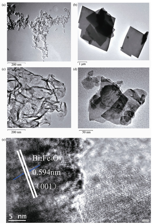
TEM images of (a) UiO-66 discoid particles, (b) Bi2Fe4O9 nanosheet, (c) g-C3N4 wrinkled sheet and (d) Bi2Fe4O9/g-C3N4/UiO-66 ternary composite (e) HRTEM images of the as-prepared sample Bi2Fe4O9/g-C3N4/UiO-66
Figure1.
TEM images of (a) UiO-66 discoid particles, (b) Bi2Fe4O9 nanosheet, (c) g-C3N4 wrinkled sheet and (d) Bi2Fe4O9/g-C3N4/UiO-66 ternary composite (e) HRTEM images of the as-prepared sample Bi2Fe4O9/g-C3N4/UiO-66
图1
TEM images of (a) UiO-66 discoid particles, (b) Bi2Fe4O9 nanosheet, (c) g-C3N4 wrinkled sheet and (d) Bi2Fe4O9/g-C3N4/UiO-66 ternary composite (e) HRTEM images of the as-prepared sample Bi2Fe4O9/g-C3N4/UiO-66
Figure1.
TEM images of (a) UiO-66 discoid particles, (b) Bi2Fe4O9 nanosheet, (c) g-C3N4 wrinkled sheet and (d) Bi2Fe4O9/g-C3N4/UiO-66 ternary composite (e) HRTEM images of the as-prepared sample Bi2Fe4O9/g-C3N4/UiO-66
Citation:
WANG Fang, ZHANG Yong-Tao, XU Yan-Li, LI Sun-Feng, WANG Xing, LIU Xue-Ting, WEI Feng-Yu. Synergistic Photocatalysis of Bi2Fe4O9/g-C3N4/UiO-66 Ternary Composites[J]. Chinese Journal of Inorganic Chemistry,
2017, 33(9): 1510-1520.
doi:
10.11862/CJIC.2017.191

Bi2Fe4O9/g-C3N4/UiO-66三元复合材料的协同光催化作用
English
Synergistic Photocatalysis of Bi2Fe4O9/g-C3N4/UiO-66 Ternary Composites
Abstract:
Bi2Fe4O9/g-C3N4/UiO-66 ternary composites synthesized by a facile hydrothermal method possess synergistically enhanced visible-light photocatalytic performance for degradation of both RhodamineB dye and colorless phenol solutions as compared with purity materials of g-C3N4, Bi2Fe4O9 and UiO-66. The ternary composite materials show increased visible light absorption, efficient separation of charge carriers, strong redox capability via Z-scheme Bi2Fe4O9/g-C3N4 heterojunction and high adsorption ability.
-
Key words:
- Bi2Fe4O9
- / UiO-66
- / visible-light
- / photocatalysis
- / synergistic effect
- / solid-state Z-scheme heterojunction
-
0 Introduction
With increasing environmental problems and the energy crisis, photocatalytic degradation of organic pollutants is one of the most important technologies for further efficient use of solar energy[1-3]. In this area, the development of high efficient and stable photo-catalysts is one of vital mission to be accomplished[4-7].
Bi2Fe4O9 has been considered as one of the most promising semiconductor materials due to its lower band gap, low cost, physical and chemical stability, availability, and can be stimulated by visible light, but, its low adsorption capacity is unfavorable to photocatalysis. In contrast, metal-organic frameworks (MOFs) have high specific surface area[8-10], excellent adsorption[11] performance, and can grow on other photocatalytic materials surface to form composite materials[12-16]. UiO-66, as one extensively investigated MOF, is a rarely observed water stable MOF, and exhibits high hydrothermal stability up to 773 K. Hence, it can be considered as an effective adsorbent to remove dyes from water. G-C3N4, as a polymeric semiconductor, has been investigated extensively due to its suitable band gap energy of about 2.70 eV, and has visible-light absorbing ability up to ca. 460 nm, moreover, it has low cost, ease of preparation, good stability, and environmental friendly features. It is noteworthy that when g-C3N4 wrinkled sheet is combined with other semiconductor, the resulted composite often exhibits solid-state Z-scheme[17-19] heterojunction stru-cture, which can enhance separation and the redox ability of the photogenerated electron-hole pairs. These features are favorable for g-C3N4 to obtain potential application in photocatalytic degradation of pollutants.
In this paper, a novel ternary Bi2Fe4O9/g-C3N4/UiO-66 composite photocatalyst was prepared. The results of structural characterization and photocatalytic experiments for degradation of RhodamineB dye and colorless phenol solutions show that 2D solid-state Z-scheme Bi2Fe4O9/g-C3N4 heterojunction structure is formed between Bi2Fe4O9 nanosheet and g-C3N4 wrinkled sheet, which plays a key role for enhanced photocatalytic activity of the binary composite. Furthermore, under the synergistic effect of high adsorption capacity of UiO-66, the resulted Bi2Fe4O9/g-C3N4/UiO-66 ternary composite exhibits the highest photocatalytic activity.
1 Experimental
1.1 Materials
Bismuth nitrate pentahydrate, six water ferric chloride, acetone, ammonia, sodium hydroxide, ZrCl4, dimethylformamide (DMF, 99%), chloroform, benzoic acid, 1, 4-benzenedicarboxylic acid (H2bdc, 98.9%), nitric acid.
1.2 Preparation of Bi2Fe4O9 and g-C3N4
Bi2Fe4O9 is produced by hydrothermal synthesis method: [Bi(NO3)3·5H2O] and [FeCl3·6H2O] in a stoichiometric ratio (1: 1 in molar ratios), were dissolved in acetone with stirring and ultrasound until comp-letely dissolved. And then distilled water was added into the solution, and ammonia was added slowly until the pH value is up to 10~11. The sediment was washed with distilled water until the pH is neutral.
The obtained sediment was added into the NaOH (8 mol·L-1) solution with ultrasonic dispersion for 30 min, then the mixture was transferred to a stainless steel teflon-lined autoclave of 50 mL capacity and maintained at 180 ℃ for 72 h. Black powder was obtained by filtration and washed with water and anhydrous ethanol.
The g-C3N4 power was synthesized according to the literature[20]. Melamine was heated at 520 ℃ for 4 h in a semi-closed crucible under air condition. The final product was washed with water and ethanol for several times and dried at 80 ℃ for 12 h. Then, g-C3N4 was obtained.
1.3 Synthesis of Bi2Fe4O9/g-C3N4 (1: 2) binary composite
Acid modified g-C3N4[21]: The as-prepared bulk g-C3N4 solid (0.500 g) was ground well and then put into 45 mL nitric acid (0.5 mol·L-1). The resulted solution was transferred to a stainless steel teflon-lined autoclave of 50 mL capacity and maintained at 135 ℃ for 6 h. The solid product was then collected by centrifugation and washed with deionized water for several times. Then, the product was dried at 60 ℃ in a vacuum oven.
Acid modified g-C3N4 (0.5 g) and Bi2Fe4O9 (1 g) were dispersed in ethanol solution(50 mL) under magnetic stirring for 24 h. The product was dried in an oven[22].
1.4 Preparation of ternary composite Bi2Fe4O9/g-C3N4/UiO-66
Bi2Fe4O9/g-C3N4/UiO-66 was synthesized as UiO-66[23]: The content of UiO-66 in composite materials was controlled by the proportion of Bi2Fe4O9/g-C3N4 and ZrCl4. For example binary composite materials Bi2Fe4O9/g-C3N4 (0.106 g), ZrCl4 (0.053 g), terephthalic acid (0.034 g) and benzoic acid (0.530 g) were intro-duced to N, N-dimethyl formamide solution (42 mL) with ultrasonic dispersion for 30 min, then the solution was transferred to a stainless steel teflon-lined autoclave of 50 mL capacity and then maintained at 393 K for 24 h. The ternary composite Bi2Fe4O9/g-C3N4/UiO-66 (2: 1) (wBi2Fe4O9/g-C3N4: wUiO-66=2: 1) was obtained after filtration, treatment with DMF and CHCl3 several times and drying under reduced pressure.
1.5 Photocatalytic experiments
The photocatalytic degradation of RhB was measured at ambient pressure and 298 K in a set of home-made photochemical reaction equipment. The light source was a PHILIPS 70 W metal halide lamp (λ < 380 nm was filtered out by a cut off filter). 20 mg of photocatalyst was added into 100 mL RhB (initial concentration, C0=10 mg·L-1) aqueous solution. Before irradiation, the suspension was stirred continuously for 12 h in the dark in order to reach the adsorption-desorption equilibrium between RhB and the photo-catalyst. The supernatant liquid was obtained through filtration by 0.22 μm filter, and examined using a Shimadzu UV-240 spectrophotometer. In order to confirm that RhB was not photodegraded by itself, control experiments were carried out under the same condition but without irradiation or photocatalyst. For comparison, the photocatalytic activities of the as-prepared samples were also tested to degradation of colorless model pollutant phenol (10 mg·L-1) under the same conditions with RhB.
1.6 Photoelectrochemical measurements
Photocurrent density was measured using a CHI electrochemical analyzer (CH instruments 660e) in a standard three-electrode configuration, with the working electrode (an effective area of 2 cm2), a platinum foil as the counter electrode, and a saturated calomel electrode (SCE) as the reference electrode. Na2SO4 (0.01 mol·L-1) was used as the electrolyte. The light source was a PHILIPS 70 W metal halide lamp (λ < 380 nm was filtered out by a cut off filter) was used as the visible light source.
1.7 Photocatalysts characterization
X-ray diffraction (XRD) patterns of the samples were determined in the range of 2θ=4°~50° by step scanning on a Rigaku D/max-2500V X-ray diffracto-meter using Cu Kα (λ=0.154 nm) radiation (U=40 kV, I=100 mA). The morphological analysis of the samples was studied using a JEM-2100F field emission transmission electron microscopy (FETEM). UV-Vis spectra were recorded at a scanning rate of 3 600 nm·min-1 in solid-state on a DUV-3700 spectrometer with the double beam, in which spectral resolution is 0.1 nm, and measure range varies from 165 nm to 3 300 nm depending on application and the use of an integrating sphere and the optional direct detection unit. The valence band X-ray photoelectron spectros-copy (XPS) was conducted using an ESCALAB250 spectrometer. Photoluminescence emission spectra (PL) were mea-sured on a PL measurement system (Fluorolog Tau-3) with the excitation wavelength of 320 nm. N2 adsorption-desorption was performed on a Tristar Ⅱ 3020M surface area and porosity analyzer at 77 K. Before the actual measurements, the sample was degassed at 70 ℃ for 3 h.
2 Results and discussion
2.1 Characterization
The microstructure of the as-prepared samples was investigated by FETEM. As shown in Fig. 1(a), UiO-66 has discoid shape with particle size at 15~20 nm. Fig. 1(b) indicated that Bi2Fe4O9 nanosheet was formed by flake structure with size at about 1~2 μm. A typical thick and wrinkled sheet structure was clearly observed in the pristine g-C3N4 in Fig. 1(c). Interestingly, it can be seen that the aggregate of g-C3N4 and UiO-66 loads on to the surface of Bi2Fe4O9 nanosheet in the Fig. 1(d). The single-crystal nature of the material can be confirmed from the high-resolution TEM image (Fig. 1(e)). Inter-planar spacings of 0.594 nm was calculated corres-ponding to the (001) plane of the orthorhombic Bi2Fe4O9 which implies the nanosheet crystals grow prefere-ntially along the (001) direction.
图1
TEM images of (a) UiO-66 discoid particles, (b) Bi2Fe4O9 nanosheet, (c) g-C3N4 wrinkled sheet and (d) Bi2Fe4O9/g-C3N4/UiO-66 ternary composite (e) HRTEM images of the as-prepared sample Bi2Fe4O9/g-C3N4/UiO-66
Figure1.
TEM images of (a) UiO-66 discoid particles, (b) Bi2Fe4O9 nanosheet, (c) g-C3N4 wrinkled sheet and (d) Bi2Fe4O9/g-C3N4/UiO-66 ternary composite (e) HRTEM images of the as-prepared sample Bi2Fe4O9/g-C3N4/UiO-66
To further observe the combination of Bi2Fe4O9, g-C3N4 and UiO-66, FETEM (Fig. 2(a)) and the EDS mapping (Fig. 2(b), (c) and (d)) were measured. The N and Zr distribution around the nanosheet shows that the ternary composites are successfully prepared, in which each component is intimately contacted with other two components.
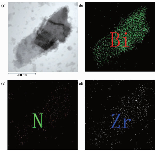 图2
(a) FETEM of Bi2Fe4O9/g-C3N4/UiO-66 (2: 1); (b) Bi, (c) N, (d) Zr distribution by EDS mapping of Bi2Fe4O9/g-C3N4/UiO-66 (2: 1)
Figure2.
(a) FETEM of Bi2Fe4O9/g-C3N4/UiO-66 (2: 1); (b) Bi, (c) N, (d) Zr distribution by EDS mapping of Bi2Fe4O9/g-C3N4/UiO-66 (2: 1)
图2
(a) FETEM of Bi2Fe4O9/g-C3N4/UiO-66 (2: 1); (b) Bi, (c) N, (d) Zr distribution by EDS mapping of Bi2Fe4O9/g-C3N4/UiO-66 (2: 1)
Figure2.
(a) FETEM of Bi2Fe4O9/g-C3N4/UiO-66 (2: 1); (b) Bi, (c) N, (d) Zr distribution by EDS mapping of Bi2Fe4O9/g-C3N4/UiO-66 (2: 1)
The XRD patterns of Bi2Fe4O9, g-C3N4 and UiO-66 shown in Fig. 3 are corresponds to those reported in the literature[24-25], and the composite displays the characteristic peaks of Bi2Fe4O9, g-C3N4 and UiO-66.This means the composite consists of the three components.
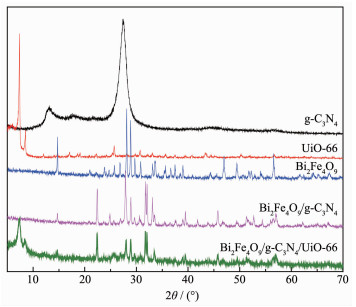 图3
XRD patterns of Bi2Fe4O9, UiO-66, g-C3N4, Bi2Fe4O9/g-C3N4 and Bi2Fe4O9/g-C3N4/UiO-66
Figure3.
XRD patterns of Bi2Fe4O9, UiO-66, g-C3N4, Bi2Fe4O9/g-C3N4 and Bi2Fe4O9/g-C3N4/UiO-66
图3
XRD patterns of Bi2Fe4O9, UiO-66, g-C3N4, Bi2Fe4O9/g-C3N4 and Bi2Fe4O9/g-C3N4/UiO-66
Figure3.
XRD patterns of Bi2Fe4O9, UiO-66, g-C3N4, Bi2Fe4O9/g-C3N4 and Bi2Fe4O9/g-C3N4/UiO-66
The N2 adsorption-desorption isotherms of Bi2Fe4O9, g-C3N4, UiO-66 and Bi2Fe4O9/g-C3N4/UiO-66 (2: 1) are displayed in Fig. 4(a), and the specific surface areas of them are 1, 11, 838 and 488 m2·g-1, respectively. The N2 adsorption-desorption isotherms of UiO-66 shows the type Ⅳ behavior, which indicates the presence of mesoporous in the material and that the pore diameter ranges from 2 to 50 nm (Fig. 4(b)). In contrast, Bi2Fe4O9 doesn′t have the mesoporous structure, whereas g-C3N4 has it, and exhibits higher BET surface area than Bi2Fe4O9.The pore size distribution of the ternary composite is not as uniform as that of UiO-66, but its pore size is even larger as shown in Fig. 4(c). Higher specific surface area and larger pore size of the structure can increase the adsorption of dye molecules on the active site, which can improve the photocatalytic activity. As known, the recombina-tion of electron-hole pairs will release energy, which can be detected by PL emission. A lower PL intensity is a general indication of a lower recombination of electron-hole pairs, resulting in higher photocatalytic activity, thus PL spectra can be used to detect efficient separation of photogenerated charge carriers. PL spectra of pure materials and composites are showed in Fig. 4(d), and the spectra intensities decrease as follows: UiO-66 > g-C3N4 > Bi2Fe4O9/g-C3N4/UiO-66 (2: 1) > Bi2Fe4O9/g-C3N4 > Bi2Fe4O9. As indicated, UiO-66 and g-C3N4 both have the relatively high recombination rate of electron-hole pairs, whereas when binary and ternary composites were constructed by the combination of Bi2Fe4O9, the separation efficiency was greatly enhanced.
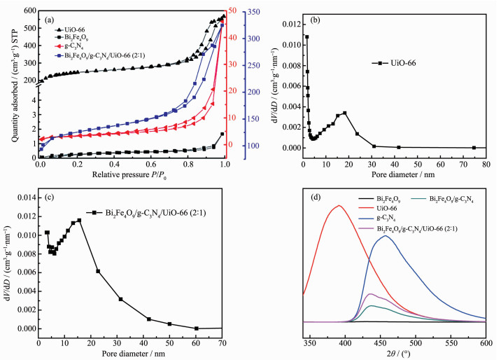 图4
(a) N2 adsorption-desorption isotherms of Bi2Fe4O9, g-C3N4, UiO-66 and Bi2Fe4O9/g-C3N4/UiO-66 (2: 1); BJH pore diameter distribution curves of UiO-66 (b) and Bi2Fe4O9/g-C3N4/UiO-66 (2: 1) (c); (d) PL spectra of Bi2Fe4O9, g-C3N4, UiO-66, Bi2Fe4O9/g-C3N4 and Bi2Fe4O9/g-C3N4/UiO-66 (2: 1)
Figure4.
(a) N2 adsorption-desorption isotherms of Bi2Fe4O9, g-C3N4, UiO-66 and Bi2Fe4O9/g-C3N4/UiO-66 (2: 1); BJH pore diameter distribution curves of UiO-66 (b) and Bi2Fe4O9/g-C3N4/UiO-66 (2: 1) (c); (d) PL spectra of Bi2Fe4O9, g-C3N4, UiO-66, Bi2Fe4O9/g-C3N4 and Bi2Fe4O9/g-C3N4/UiO-66 (2: 1)
图4
(a) N2 adsorption-desorption isotherms of Bi2Fe4O9, g-C3N4, UiO-66 and Bi2Fe4O9/g-C3N4/UiO-66 (2: 1); BJH pore diameter distribution curves of UiO-66 (b) and Bi2Fe4O9/g-C3N4/UiO-66 (2: 1) (c); (d) PL spectra of Bi2Fe4O9, g-C3N4, UiO-66, Bi2Fe4O9/g-C3N4 and Bi2Fe4O9/g-C3N4/UiO-66 (2: 1)
Figure4.
(a) N2 adsorption-desorption isotherms of Bi2Fe4O9, g-C3N4, UiO-66 and Bi2Fe4O9/g-C3N4/UiO-66 (2: 1); BJH pore diameter distribution curves of UiO-66 (b) and Bi2Fe4O9/g-C3N4/UiO-66 (2: 1) (c); (d) PL spectra of Bi2Fe4O9, g-C3N4, UiO-66, Bi2Fe4O9/g-C3N4 and Bi2Fe4O9/g-C3N4/UiO-66 (2: 1)
Fig. 5 shows that the Bi2Fe4O9/g-C3N4/UiO-66 (2: 1) electrode has a strong instant photoresponse to the visible light irradiation. The short-circuit photocurrent density of the Bi2Fe4O9/g-C3N4/UiO-66 (2: 1) electrode is as great as 3 times that of the UiO-66 electrode. This demonstrates that the separation rate of photogenerated holes and electrons increases because of the loading of g-C3N4 and UiO-66. More photogenerated electrons collected from the Bi2Fe4O9/g-C3N4/UiO-66 (2: 1) electrode suggest that more photogenerated holes survive from recombination or from the longer lifetime that the holes had.
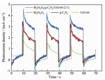 图5
Short-circuit photocurrent density versus time plotted (0 V versus SCE) for Bi2Fe4O9/g-C3N4/ UiO-66 (2: 1), Bi2Fe4O9, g-C3N4 and UiO-66 electrodes in 0.01 mol·L-1 Na2SO4 solution under visible light irradiation
Figure5.
Short-circuit photocurrent density versus time plotted (0 V versus SCE) for Bi2Fe4O9/g-C3N4/ UiO-66 (2: 1), Bi2Fe4O9, g-C3N4 and UiO-66 electrodes in 0.01 mol·L-1 Na2SO4 solution under visible light irradiation
图5
Short-circuit photocurrent density versus time plotted (0 V versus SCE) for Bi2Fe4O9/g-C3N4/ UiO-66 (2: 1), Bi2Fe4O9, g-C3N4 and UiO-66 electrodes in 0.01 mol·L-1 Na2SO4 solution under visible light irradiation
Figure5.
Short-circuit photocurrent density versus time plotted (0 V versus SCE) for Bi2Fe4O9/g-C3N4/ UiO-66 (2: 1), Bi2Fe4O9, g-C3N4 and UiO-66 electrodes in 0.01 mol·L-1 Na2SO4 solution under visible light irradiation
Fig. 6(a) shows the UV-Vis absorption spectra of Bi2Fe4O9, g-C3N4 and UiO-66. Two absorption bands of Bi2Fe4O9 are observed in the visible region, indicating that the sample can serve as a photocatalyst driven by visible light. The first absorption from 400 to 600 nm primarily results from two types of excitations overlapping each other. The first excitation process is due to the pair excitation process: 6A1g+6A1g → 4T1g(4G)+4T1g(4G) and the second one is due to the excitation from 6A1g to 4Eg, 4A1g(4G) ligand field transitions (octah-edral coordination) and 6A1 to 4T2(4G) ligand field tran-sitions (tetrahedral coordination) as well as the charge transfer band tail. The second absorption from 610 to 770 nm can then be assigned to the d-d transitions of Fe3+[26]. There are two absorption bands of UiO-66: the first absorption in the ultraviolet region primarily results from the direct transition of valence electrons and the second absorption from 380 to 600 nm can then be assigned to the crystal lattice defects. G-C3N4 wrinkled sheet can absorb light of less than 460 nm and the peak intensity is weaker in ultraviolet region. The band gap energy Eg of Bi2Fe4O9, g-C3N4 and UiO-66 can be determined using the following equation: αhν=A(hν-Eg)n/2, where α, ν, Eg and A are absorption coefficient, light frequency, band gap and a constant, respectively. Among them, n depends on the transition process (n=1 for direct transition or n=4 for indirect transition[27-28]). Bi2Fe4O9 has two low band gap Eg: 1.84 eV and 1.49 eV, which indicates the response to visible light. The Eg of g-C3N4 and UiO-66 are 2.81[29] and 3.49 eV (Fig. 6(b)), respectively.
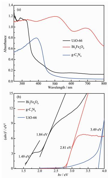 图6
(a) UV-Vis absorption spectra of Bi2Fe4O9, UiO-66 and g-C3N4; (b) Band-gaps of Bi2Fe4O9, UiO-66 and g-C3N4
Figure6.
(a) UV-Vis absorption spectra of Bi2Fe4O9, UiO-66 and g-C3N4; (b) Band-gaps of Bi2Fe4O9, UiO-66 and g-C3N4
图6
(a) UV-Vis absorption spectra of Bi2Fe4O9, UiO-66 and g-C3N4; (b) Band-gaps of Bi2Fe4O9, UiO-66 and g-C3N4
Figure6.
(a) UV-Vis absorption spectra of Bi2Fe4O9, UiO-66 and g-C3N4; (b) Band-gaps of Bi2Fe4O9, UiO-66 and g-C3N4
The valence band of UiO-66 is 2.49 eV[30], and those of g-C3N4 and Bi2Fe4O9 are 1.51 and 2.51 eV, respectively according to Wang[31]. Combined with the energy gap and valence band, the CB positions of UiO-66, g-C3N4 and Bi2Fe4O9 can be calculated to be -1.00, -1.30 and 0.67 eV, respectively. The middle band of Bi2Fe4O9 is 1.02 eV. CB positions for g-C3N4 and UiO-66 are more negative than O2/·O2- (-0.33 eV) and O2/HOO· (-0.037 eV), indicating that it is possible for the transfer of photogenerated electrons from CB to O2 to form ·O2-, and then become ·OH free radicals.
2.2 Adsorption activity of Bi2Fe4O9, g-C3N4, UiO-66 and the composites
UiO-66 and Bi2Fe4O9/g-C3N4/UiO-66 (2: 1) display high adsorption capacity, and rapid adsorption process happens in the first three hours, and then reaches to balance (Fig. 7(a)). Bi2Fe4O9 and g-C3N4 display poor adsorption capacity of RhB in contrast with UiO-66 which is due to a large BET surface area of UiO-66. As shown in Fig. 7(b), the adsorption activities of com-posites are between those of Bi2Fe4O9 and UiO-66, and increase with the increasing of the UiO-66 content.
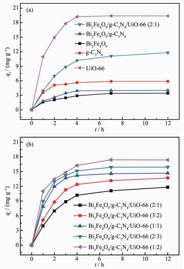 图7
(a) Adsorption capacity of RhB onto Bi2Fe4O9, g-C3N4, UiO-66, Bi2Fe4O9/g-C3N4 and Bi2Fe4O9/ g-C3N4/UiO-66 (2: 1); (b) Adsorption capacity of RhB onto the ternary composites with different mass ratios of Bi2Fe4O9/g-C3N4 to UiO-66
Figure7.
(a) Adsorption capacity of RhB onto Bi2Fe4O9, g-C3N4, UiO-66, Bi2Fe4O9/g-C3N4 and Bi2Fe4O9/ g-C3N4/UiO-66 (2: 1); (b) Adsorption capacity of RhB onto the ternary composites with different mass ratios of Bi2Fe4O9/g-C3N4 to UiO-66
图7
(a) Adsorption capacity of RhB onto Bi2Fe4O9, g-C3N4, UiO-66, Bi2Fe4O9/g-C3N4 and Bi2Fe4O9/ g-C3N4/UiO-66 (2: 1); (b) Adsorption capacity of RhB onto the ternary composites with different mass ratios of Bi2Fe4O9/g-C3N4 to UiO-66
Figure7.
(a) Adsorption capacity of RhB onto Bi2Fe4O9, g-C3N4, UiO-66, Bi2Fe4O9/g-C3N4 and Bi2Fe4O9/ g-C3N4/UiO-66 (2: 1); (b) Adsorption capacity of RhB onto the ternary composites with different mass ratios of Bi2Fe4O9/g-C3N4 to UiO-66
RhB dye was used as probing molecules to explore the photocatalytic degradation property of the as-prepared samples. For low concentration pollutants, the pseudo-first order kinetic model can be adopted according to the following equation:
where Ct is the concentration of pollutant (mg·L-1) in the time of t, C0 is the adsorption equilibrium concen-tration of pollutant before irradiation (mg·L-1), t is the reaction time (min), and k is the reaction rate constant (min-1). As shown in Fig. 8(a), the photocatalytic activities are increased as the following order: g-C3N4 < Bi2Fe4O9 < UiO-66 < Bi2Fe4O9/g-C3N4 < Bi2Fe4O9/g-C3N4/UiO-66 (2: 1). The photocatalytic performance of ternary composites with the different ratios was also investi-gated, and they generally display better photodegra-dation activity than pure materials and binary com-posite (Fig. 8(b)). It can be seen that the mass ratio of 2: 1 is the optimum value to achieve high photode-gradation activity.
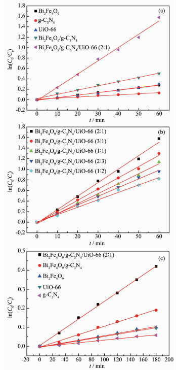 图8
Kinetics of RhB photodegradation on: (a) Bi2Fe4O9, g-C3N4, UiO-66, Bi2Fe4O9/g-C3N4 and Bi2Fe4O9/ g-C3N4/UiO-66; (b) Ternary composites with the different ratios; Kinetics of phenol (10 mg·L-1) photodegradation on: (c) Bi2Fe4O9, g-C3N4, UiO-66, Bi2Fe4O9/g-C3N4 and Bi2Fe4O9/g-C3N4/UiO-66 (2: 1)
Figure8.
Kinetics of RhB photodegradation on: (a) Bi2Fe4O9, g-C3N4, UiO-66, Bi2Fe4O9/g-C3N4 and Bi2Fe4O9/ g-C3N4/UiO-66; (b) Ternary composites with the different ratios; Kinetics of phenol (10 mg·L-1) photodegradation on: (c) Bi2Fe4O9, g-C3N4, UiO-66, Bi2Fe4O9/g-C3N4 and Bi2Fe4O9/g-C3N4/UiO-66 (2: 1)
图8
Kinetics of RhB photodegradation on: (a) Bi2Fe4O9, g-C3N4, UiO-66, Bi2Fe4O9/g-C3N4 and Bi2Fe4O9/ g-C3N4/UiO-66; (b) Ternary composites with the different ratios; Kinetics of phenol (10 mg·L-1) photodegradation on: (c) Bi2Fe4O9, g-C3N4, UiO-66, Bi2Fe4O9/g-C3N4 and Bi2Fe4O9/g-C3N4/UiO-66 (2: 1)
Figure8.
Kinetics of RhB photodegradation on: (a) Bi2Fe4O9, g-C3N4, UiO-66, Bi2Fe4O9/g-C3N4 and Bi2Fe4O9/ g-C3N4/UiO-66; (b) Ternary composites with the different ratios; Kinetics of phenol (10 mg·L-1) photodegradation on: (c) Bi2Fe4O9, g-C3N4, UiO-66, Bi2Fe4O9/g-C3N4 and Bi2Fe4O9/g-C3N4/UiO-66 (2: 1)
These behaviors indicate that Bi2Fe4O9, g-C3N4 and UiO-66 have the lower photodegradation efficien-cies, which can be interpreted as their lower adsorption ability or due to the higher recombination rate of electron-hole pairs, resulting in poor photocatalytic degradation efficiency.
In addition, phenol, as a colorless substance without absorbing visible-light, was used as the second model pollutant to further evaluate the visible light photocatalytic performance of the as-prepared samples under visible light, and the obtained results are illustrated in Fig. 8(c). It is clear that the photode-gradation efficiency follows the same order: g-C3N4 < Bi2Fe4O9 < UiO-66 < Bi2Fe4O9/g-C3N4 < Bi2Fe4O9/g-C3N4/UiO-66 (2: 1), as compared to photodegradation of RhB. After 180 min irradiation, about 65% percent of phenol was removed over Bi2Fe4O9/g-C3N4/UiO-66 (2: 1) com-posites. By comparing Fig. 7(a) with Fig. 7(c), one can see that the photocatalytic activity for phenol is lower than that for RhB. This phenomenon is often observed for photocatalytic study.
The regeneration of the photocatalyst is one of the important steps for considering in practical applications. The stability of Bi2Fe4O9/g-C3N4/UiO-66 (2: 1) was investigated, and after each photodegrada-tion, it was separated from solution by centrifuge, and can be reused without considerable amount of mass loss. As shown in Fig. 9(a), (b), after three cycles of degradation RhB, the photodegradation kinetics constant of Bi2Fe4O9/g-C3N4/UiO-66 (2: 1) is 87% of the first cycle and after three cycles of photodegradation of phenol (10 mg·L-1), the k value stabilizes at about 0.119 min-1, which is 85.6% of the first cycle. indica-ting that composite material has the good regeneration performance.
 图9
(a) Kinetics of RhB photodegradation on the recycled Bi2Fe4O9/g-C3N4/UiO-66 (2: 1), (b) Kinetics of phenol photodegradation on the recycled Bi2Fe4O9/g-C3N4/UiO-66 (2: 1)
Figure9.
(a) Kinetics of RhB photodegradation on the recycled Bi2Fe4O9/g-C3N4/UiO-66 (2: 1), (b) Kinetics of phenol photodegradation on the recycled Bi2Fe4O9/g-C3N4/UiO-66 (2: 1)
图9
(a) Kinetics of RhB photodegradation on the recycled Bi2Fe4O9/g-C3N4/UiO-66 (2: 1), (b) Kinetics of phenol photodegradation on the recycled Bi2Fe4O9/g-C3N4/UiO-66 (2: 1)
Figure9.
(a) Kinetics of RhB photodegradation on the recycled Bi2Fe4O9/g-C3N4/UiO-66 (2: 1), (b) Kinetics of phenol photodegradation on the recycled Bi2Fe4O9/g-C3N4/UiO-66 (2: 1)
2.3 Photocatalytic mechanism of Bi2Fe4O9/g-C3N4/UiO-66
To investigate the active ingredient in photocatal-ytic process of Bi2Fe4O9/g-C3N4/UiO-66, EDTA-2Na, t-BuOH and BQ were as the probe molecules[32-33]. After adding each probe molecule, the photodegradation rate of the ternary composite is generally decreased, and the inhibition degree is decreased in the following order: EDTA-2Na > BQ > t-BuOH. As shown in Fig. 10, h+ radicals are the main active oxygen species in the degradation of RhB, followed by ·O2- radicals and ·OH radicals[34-36].
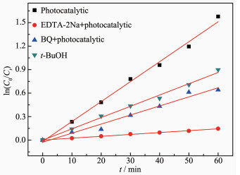 图10
Species trapping experiments for degradation of RhB over Bi2Fe4O9/g-C3N4/UiO-66 (2: 1)
Figure10.
Species trapping experiments for degradation of RhB over Bi2Fe4O9/g-C3N4/UiO-66 (2: 1)
图10
Species trapping experiments for degradation of RhB over Bi2Fe4O9/g-C3N4/UiO-66 (2: 1)
Figure10.
Species trapping experiments for degradation of RhB over Bi2Fe4O9/g-C3N4/UiO-66 (2: 1)
The ESR technique was further used to detect the presence of ·OH and ·O2- radicals in the Bi2Fe4O9 /g-C3N4/UiO-66 (2: 1) photocatalytic reaction systems under visible light. As shown in Fig. 10, for Bi2Fe4O9/g-C3N4/UiO-66 (2: 1) samples, the four characteristic peaks of the DMPO-·OH adducts (Fig. 11(a)) and six characteristic peaks of DMPO-·O2- adducts (Fig. 11(b)) are observed, Therefore, according to the above results of the active species trapping experiments and this ESR analysis, it can be inferred that the ·O2- played a major role in the Bi2Fe4O9/g-C3N4/UiO-66 (2: 1) photo-catalytic reactions rather than the ·OH.
 图11
DMPO spin-trapping ESR spectra for Bi2Fe4O9/ g-C3N4/UiO-66 (2: 1): (a) in aqueous dispersion for DMPO-·OH, (b) in methanol dispersion for DMPO-·O2-
Figure11.
DMPO spin-trapping ESR spectra for Bi2Fe4O9/ g-C3N4/UiO-66 (2: 1): (a) in aqueous dispersion for DMPO-·OH, (b) in methanol dispersion for DMPO-·O2-
图11
DMPO spin-trapping ESR spectra for Bi2Fe4O9/ g-C3N4/UiO-66 (2: 1): (a) in aqueous dispersion for DMPO-·OH, (b) in methanol dispersion for DMPO-·O2-
Figure11.
DMPO spin-trapping ESR spectra for Bi2Fe4O9/ g-C3N4/UiO-66 (2: 1): (a) in aqueous dispersion for DMPO-·OH, (b) in methanol dispersion for DMPO-·O2-
In summary, a possible mechanism of photocatal-ysis is proposed. As shown in Fig. 12, Bi2Fe4O9 and g-C3N4 were inspired by the visible light, and photopro-duction electrons are transferred from valence band (VB) via the calculated band-gap to the conduction band (CB). The VB edges of g-C3N4 is 1.51 eV which had no sufficient force to drive -OH oxidation to form ·OH, however the CB of Bi2Fe4O9 is 0.67 eV, then the dissolved O2 can not capture the photogenerated electron at CB of Bi2Fe4O9 to yield the superoxide radical anion, ·O2-, to degrade RhB. On the other hand, the h+ radicals on VB of g-C3N4 have too low oxidation capacity to degrade RhB. However, Bi2Fe4O9/ g-C3N4 may act as a solid Z-scheme photocatalyst, in which the photogenerated electrons on the CB of Bi2Fe4O9 can combine with h+ on the VB of g-C3N4, as a result, VB of Bi2Fe4O9 for h+ is more positive than VB of g-C3N4, meanwhile CB of g-C3N4 for e- is more negative than CB of Bi2Fe4O9. In other words, h+ left on VB of Bi2Fe4O9 has higher oxidation capacity to degrade RhB, and e- left on CB of g-C3N4 can be more readily trapped by O2 to yield ·O2-. After forming ternary composite, e- on the CB of g-C3N4 transfers to the CB of UiO-66, and the dissolved O2 captures e- on the CB of UiO-66 to yield the superoxide radical anion, ·O2-, and then the HOO· radical upon protonation. The ·OH radical can be produced from the trapped electron after formation of the HOO· radical by the following equations[37].
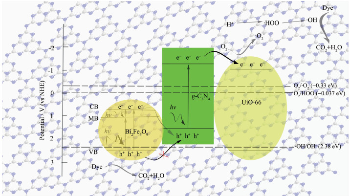 图12
Mechanism diagram of the RhB photodegradation on Bi2Fe4O9/g-C3N4/UiO-66 ternary composite
Figure12.
Mechanism diagram of the RhB photodegradation on Bi2Fe4O9/g-C3N4/UiO-66 ternary composite
图12
Mechanism diagram of the RhB photodegradation on Bi2Fe4O9/g-C3N4/UiO-66 ternary composite
Figure12.
Mechanism diagram of the RhB photodegradation on Bi2Fe4O9/g-C3N4/UiO-66 ternary composite
The active oxygen species ·O2-, HOO· and ·OH radicals have taken part in the degradation of RhB, meanwhile, the photogenerated holes in the VB of Bi2Fe4O9 play a major role, and can directly destroy the adsorbed RhB or react with H2O to yield ·OH radicals.
3 Conclusions
In summary, Bi2Fe4O9/g-C3N4/UiO-66 ternary composites were synthesized by a facile solvothermal method, and exhibit higher visible light photocatalytic activities for degradation of RhB dye and colorless phenol solutions as compared with purity materials and binary composite materials. The synergistic effect of photocatalysis is due to big adsorption capacity of UiO-66 and the effective separation of electron-hole pair and their strong redox capability generated by Z-scheme Bi2Fe4O9/g-C3N4 heterojunction B.
-
-
[1]
Sastre F, Puga A V, Liu L, et al. J. Am. Chem. Soc., 2014, 136:6798-6801 doi: 10.1021/ja500924t
-
[2]
Lin C H, Chao J H, Liu C H, et al. Langmuir, 2008, 24:9907-9915 doi: 10.1021/la800572g
-
[3]
Zhang Y H, Tang Z R, Fu X Z, et al. ACS Nano, 2010, 4:7303-7314 doi: 10.1021/nn1024219
-
[4]
Dolbecq A, Mialane P, Keita B, et al. Mater. Chem., 2012, 22:24509-24521 doi: 10.1039/c2jm33246a
-
[5]
Kubacka A, Fernández-García M, Colón G. Chem. Rev., 2012, 112:1555-1614 doi: 10.1021/cr100454n
-
[6]
Fan W Q, Zhang Q H, Wang Y. Phys. Chem. Chem. Phys., 2013, 15:2632-2649 doi: 10.1039/c2cp43524a
-
[7]
Chen X B, Shen S H, Guo L J, et al. Chem. Rev., 2010, 110:6503-6570 doi: 10.1021/cr1001645
-
[8]
Eddaoudi M, Kim J, Rosi N, et al. Science, 2002, 295:469-472 doi: 10.1126/science.1067208
-
[9]
Horcajada P, Serre C, Vallet-Regí M, et al. Angew. Chem., 2006, 118:6120-6124 doi: 10.1002/(ISSN)1521-3757
-
[10]
Lee Y R, Kim J, Ahn W S. Korean J. Chem. Eng., 2013, 30:1667-1680 doi: 10.1007/s11814-013-0140-6
-
[11]
Hasegawa S, Horike S, Matsuda R S, et al. J. Am. Chem. Soc., 2007, 129:2607-2614 doi: 10.1021/ja067374y
-
[12]
Li H L, Eddaoudi M, O'Keeffe M, et al. Nature, 1999, 402:276-279 doi: 10.1038/46248
-
[13]
Yaghi O M, O'Keeffe M, Ockwig N W, et al. Nature, 2003, 423:705-714 doi: 10.1038/nature01650
-
[14]
Kitagawa S, Kitaura R, Noro S I. Angew. Chem. Int. Ed., 2004, 43:2334-2375 doi: 10.1002/(ISSN)1521-3773
-
[15]
Kitagawa S, Matsuda R. Chem. Rev., 2007, 251:2490-2509 http://www.sciencedirect.com/science/article/pii/S0010854507001464
-
[16]
Férey G. Chem. Soc. Rev., 2008, 37:191-214 doi: 10.1039/B618320B
-
[17]
Bai Y, Wang P Q, Liu J Y, et al. RSC Adv., 2014, 4:19456-19461 doi: 10.1039/c4ra01629g
-
[18]
Zhou P, Yu J G, Jaroniec M. Adv. Mater., 2014, 26:4920-4935 doi: 10.1002/adma.201400288
-
[19]
Sasaki Y, Kato H, Kudo A. J. Am. Chem. Soc., 2013, 135:5441-5449 doi: 10.1021/ja400238r
-
[20]
He Y M, Zhang L H, Fan M H, et al. Sol. Energy Mater. Sol. Cells, 2015, 137:175-184 doi: 10.1016/j.solmat.2015.01.037
-
[21]
Zhang L G, Liu D, Guan J. et al. Mater. Res. Bull., 2014, 59:84-92 doi: 10.1016/j.materresbull.2014.06.021
-
[22]
Zang Y P, Li L P, Li X G, et al. Chem. Eng. J., 2014, 246:277-286 doi: 10.1016/j.cej.2014.02.068
-
[23]
Cavka J H, Jakobsen S, Olsbye U N, et al. J. Am. Chem. Soc., 2008, 130:13850-13851 doi: 10.1021/ja8057953
-
[24]
Liu Y, Zuo R. Particuology, 2013, 11:581-587 doi: 10.1016/j.partic.2012.11.002
-
[25]
Zhou J J, Wang R, Liu X L, et al. Appl. Surf. Sci., 2015, 346:278-283 doi: 10.1016/j.apsusc.2015.03.210
-
[26]
Sherman D M. Phys. Chem. Miner., 1985, 12:161-175 doi: 10.1007/BF00308210
-
[27]
Butler M A. J. Appl. Phys., 1914, 48:1914-1920 doi: 10.1063/1.323948
-
[28]
Lin J, Lin J, Zhu Y F. Inorg. Chem., 2007, 46:8372-8378 doi: 10.1021/ic701036k
-
[29]
Yan T, Tian J, Guan W, et al. Appl. Catal. B:Environ., 2017, 202:84-94 doi: 10.1016/j.apcatb.2016.09.017
-
[30]
Li S, Wang X, Chen Q, et al. RSC Adv., 2015, 5:53198-53206 doi: 10.1039/C5RA05477J
-
[31]
Wang X, Zhang M, Tian P, et al. Appl. Surf. Sci., 2014, 321:144-149 doi: 10.1016/j.apsusc.2014.09.166
-
[32]
Chen D, Jiang Z, Geng J, et al. Ind. Eng. Chem. Res., 2007, 46:2741-2746 doi: 10.1021/ie061491k
-
[33]
Mohapatra L, Parida K, Satpathy M. J. Phys. Chem. C, 2012, 116:13063-13070 doi: 10.1021/jp300066g
-
[34]
Xiong P, Chen Q, He M Y, et al. J. Mater. Chem., 2012, 22:17485-17493 doi: 10.1039/c2jm31522j
-
[35]
Xiong P, Wan L J, Sun X Q, et al. Ind. Eng. Chem. Res., 2013, 53:10105-10113 doi: 10.1021/ie400739e
-
[36]
Chen Q, He Q Q, Lü M M, et al. Appl. Surf. Sci., 2014, 311:230-238 doi: 10.1016/j.apsusc.2014.05.046
-
[37]
Su F Z, Mathew S C, Lipner G, et al. J. Am. Chem. Soc., 2010, 132:16299-16301 doi: 10.1021/ja102866p
-
[1]
-

Figure 1 TEM images of (a) UiO-66 discoid particles, (b) Bi2Fe4O9 nanosheet, (c) g-C3N4 wrinkled sheet and (d) Bi2Fe4O9/g-C3N4/UiO-66 ternary composite (e) HRTEM images of the as-prepared sample Bi2Fe4O9/g-C3N4/UiO-66

Figure 2 (a) FETEM of Bi2Fe4O9/g-C3N4/UiO-66 (2: 1); (b) Bi, (c) N, (d) Zr distribution by EDS mapping of Bi2Fe4O9/g-C3N4/UiO-66 (2: 1)

Figure 3 XRD patterns of Bi2Fe4O9, UiO-66, g-C3N4, Bi2Fe4O9/g-C3N4 and Bi2Fe4O9/g-C3N4/UiO-66

Figure 4 (a) N2 adsorption-desorption isotherms of Bi2Fe4O9, g-C3N4, UiO-66 and Bi2Fe4O9/g-C3N4/UiO-66 (2: 1); BJH pore diameter distribution curves of UiO-66 (b) and Bi2Fe4O9/g-C3N4/UiO-66 (2: 1) (c); (d) PL spectra of Bi2Fe4O9, g-C3N4, UiO-66, Bi2Fe4O9/g-C3N4 and Bi2Fe4O9/g-C3N4/UiO-66 (2: 1)

Figure 5 Short-circuit photocurrent density versus time plotted (0 V versus SCE) for Bi2Fe4O9/g-C3N4/ UiO-66 (2: 1), Bi2Fe4O9, g-C3N4 and UiO-66 electrodes in 0.01 mol·L-1 Na2SO4 solution under visible light irradiation

Figure 6 (a) UV-Vis absorption spectra of Bi2Fe4O9, UiO-66 and g-C3N4; (b) Band-gaps of Bi2Fe4O9, UiO-66 and g-C3N4

Figure 7 (a) Adsorption capacity of RhB onto Bi2Fe4O9, g-C3N4, UiO-66, Bi2Fe4O9/g-C3N4 and Bi2Fe4O9/ g-C3N4/UiO-66 (2: 1); (b) Adsorption capacity of RhB onto the ternary composites with different mass ratios of Bi2Fe4O9/g-C3N4 to UiO-66

Figure 8 Kinetics of RhB photodegradation on: (a) Bi2Fe4O9, g-C3N4, UiO-66, Bi2Fe4O9/g-C3N4 and Bi2Fe4O9/ g-C3N4/UiO-66; (b) Ternary composites with the different ratios; Kinetics of phenol (10 mg·L-1) photodegradation on: (c) Bi2Fe4O9, g-C3N4, UiO-66, Bi2Fe4O9/g-C3N4 and Bi2Fe4O9/g-C3N4/UiO-66 (2: 1)

Figure 9 (a) Kinetics of RhB photodegradation on the recycled Bi2Fe4O9/g-C3N4/UiO-66 (2: 1), (b) Kinetics of phenol photodegradation on the recycled Bi2Fe4O9/g-C3N4/UiO-66 (2: 1)

Figure 10 Species trapping experiments for degradation of RhB over Bi2Fe4O9/g-C3N4/UiO-66 (2: 1)

Figure 11 DMPO spin-trapping ESR spectra for Bi2Fe4O9/ g-C3N4/UiO-66 (2: 1): (a) in aqueous dispersion for DMPO-·OH, (b) in methanol dispersion for DMPO-·O2-
-


 下载:
下载:


 扫一扫看文章
计量
- PDF下载量: 42
- 文章访问数: 2342
- HTML全文浏览量: 514
 下载:
下载:
