Received Date:
20 July 2025 Accepted Date:
25 August 2025 Revised Date:
15 August 2025 Available Online:
15 April 2026
Abstract:
Hydrogel electrolyte have attracted widely interest for aqueous zinc-ion batteries because of their multi-functionality and intrinsic safety. However, the unstable anode/electrolyte interface by dendrite and side reaction (HER) restricted the cycling of Zn anode, especially at high utilization. Herein, we propose an interface engineering strategy by introducing dimethylformamide (DMF) to polyacrylamide (PAM) electrolyte which could construct the polymer-inorganic bilayer solid electrolyte interphase (SEI) to improve the interface stability and compatibility. Internal Zn5(OH)6(CO3)2 provided high modulus to suppress the dendrite physically and external polymer exhibited flexibility to accommodate the volume change of Zn during cycles. Meanwhile, larger polymer clusters were induced by enhanced hydrogen-bond interactions, resulted in higher shear strength and interfacial adhesion. Additionally, DMF regulated the crystal orientation along (100) crystal plane and solvation structure of Zn2+ with PAM, enabling dense deposition and reduced by-products. Consequently, the Zn anode could provide an impressive lifespan (0.5 mA/cm2@0.5 mAh/cm2, 4000 h; 30 mA/cm2@15 mAh/cm2, 650 h). More importantly, high utilization (68%) was achieved using ultra-thin Zn (10 µm) with superior stability (2 mA/cm2@4 mAh/cm2, 1200 h). Coupled with iodine cathode, the Zn-I2 cell could provide an initial capacity of 184.5 mAh/g at the low ratio of anode/cathode capacity (N/P: 4.3) and ~86.4% retention over 500 cycles. This work provides a promising approach to construct robust interface by hydrogel electrolyte towards practical zinc-ion batteries.
The energy crisis and environmental pollution increase the demand for sustainable and clean energy, thus promoting the development of advanced energy storage system [1-3]. Although lithium-ion (Li-ion) batteries have shown advance in high energy density, safety issues of electrolyte and high cost of Li metal bring concerns to people for further application [4,5]. As a candidate, aqueous zinc-ion batteries (AZIBs) could provide high safety and environmental friendliness in terms of aqueous electrolyte [6]. And Zn metal anode possess high theoretical capacities (820 mAh/g) with low redox potential (−0.76 V vs. SHE), expected to achieve ideal energy density, thus showing great potential in grid-scale energy storage [7,8]. However, during the plating process, zinc ions trend to adsorb and aggregate on the rough surface and form dendrite, accompanying by competitive hydrogen evolution reaction (HER) and passivation products (Zn4(SO4)4(OH)6·xH2O), severely damaging the reversibility and cycling lifetime of the anode [9,10].
To overcome above problems, great effort has been devoted to the anode interface and solvation structure of Zn2+ such as structure design of anode [11], interface protection [12,13], novel separator [14] and electrolyte optimization [15]. Among them, electrolyte could not only regulate the growth rate of the specific crystal plane, but also reduce the amount of water in the solvation structure, providing easiest way to suppress dendrite and HER [16]. Compared to liquid electrolyte, hydrogel electrolyte consisting of polymer matrix and aqueous electrolyte, provide mechanical property and good ionic conductivity without liquid leaking [17]. Polar functional groups of polymers provide positive effect to regulate ion diffusion and deposition behaviors by the ion-dipole interaction [18,19]. Besides, high-modulus hydrogels have been proved effectively to inhibit Zn dendrite by mechanical constraints. Although current methods such as dual-network structure [20], electrostatic effect [21] and phase separation [22] deliver encouraging advancements in improving Young’s modulus of hydrogel, compatibility of the interface is still unresolved [23,24]. Limited area from solid-solid contact increased interfacial impedance, adding difficulty for immigration of zinc ions, as well as facile detachment during cycles due to the weak adhesion of the hydrogel. Therefore, it still faced a great challenge to construct the stable interface of electrode/electrolyte with high compatibility for hydrogel electrolyte.
To improve the interface contact, in-situ polymerization and solution-gelation conversion have been developed to enhance the interaction between hydrogel and Zn atom on the substrate [25,26]. Compared to ex-situ prepared hydrogel, liquid electrolyte containing monomers could infiltrate the anode substrate before in-situ polymerization, enabling complete interfacial contact and well-bonded strength. And another way is solution-gelation conversion, where liquidity of polymer electrolyte was improved by heating and solidified into stable solid-solid interface without interspaces. This method also provided adaptive interface for repairing the interfacial gaps during electrochemical cycles. However, limited sites on the interface resulted in deficiency in bonding, as well as initiators in polymerization process, causing potential damages to battery performance [27]. Besides, volumetric changes of Zn anode during cycles increased the risk of SEI rupture and dendrite penetration, especially under the condition of high utilization [28].
Herein, we presented an interface engineering strategy to construct the stable anode/electrolyte interface by introducing DMF to PAM hydrogel (PAM/DMF-0.1), which generated a polymer-inorganic bilayer solid electrolyte interphase (SEI), filling interface interspace and increasing interface compatibility. Internal inorganic SEI (Zn5(OH)6(CO3)2) could provide high modulus to suppress the dendrite penetration while external polymer SEI provided toughness to accommodate the volumetric change during electrochemical cycles. Meanwhile, DMF could also induce the formation of larger polymer cluster by the hydrogen-bond interaction, leading to higher shear and higher interfacial adhesion. Besides, hydrogel could also regulate the deposition orientation of Zn2+ along (100) crystal plane by specific adsorption and solvation structure of Zn2+ by the synergistic effect of PAM and DMF, as well as anchor the free water, enabling dendrite-free deposition and reduced side reaction. Benefiting from these advantages, the Zn-Zn cells with PAM/DMF-0.1 electrolyte exhibited outstanding durability (0.5 mA/cm2@0.5 mAh/cm2; 4000 h) and high tolerance for high current density/capacity (30 mA/cm2@15 mAh/cm2; 650 h). Even under depth discharging of 4 mAh/cm2 (68% utilization) with ultra-thin Zn electrode (10 µm), the Zn-Zn cell could still achieve stable cycles over 1200 h. When coupled with the carbon-loaded iodine cathode (SP@I2), the Zn-I2 cell at the low N/P (4.3) delivered an initial capacity of 184.5 mAh/g with excellent stability (capacity retention of 86.4% after 500 cycles). The assembled pouch cell further highlights the practical values of hydrogel electrolyte. This work demonstrates a new promising on hydrogel electrolyte for enhancing interfacial stability and promoting the development of AZIBs.
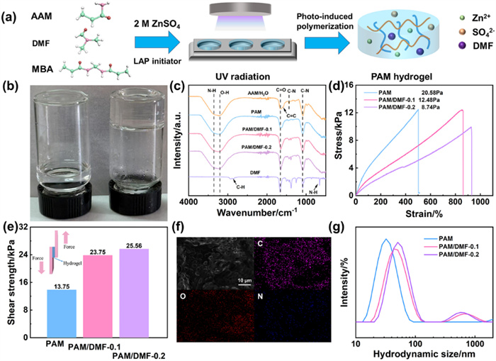
The fabrication process of the DMF modified PAM hydrogel electrolyte was illustrated in Fig. 1a. Original monomers were firstly dissolved in 2 mol/L ZnSO4 aqueous solution with different ration of DMF additive (10% and 20%, v/v). After exposed to UV radiation, quasi-solid electrolytes (PAM/DMF-0.1, PAM/DMF-0.2) were obtained by fast photo-induced polymerization. As shown in Fig. 1b, the optical images of the hydrogel (PAM/DMF-0.1) showed a transparent solid without liquidity, indicating the formation of cross-linked 3D network. The structural information of the monomer, DMF and various PAM were investigated by attenuated total reflectance Fourier transform infrared (ATR-FTIR) spectra (Fig. 1c). The peak located at 1590 cm-1 stood for stretching vibration of C=C and disappeared in all PAM hydrogel, indicating the successful polymerization of the monomers [18]. Besides, obvious peaks plotted at 3368, 1660, 1440 and 1076 cm-1, represented the characteristic vibration of N—H, C=O and C—N, respectively [29].
Figure 1
Figure 1.
(a) Schematic of the preparation process of various PAM hydrogels. (b) Optical images of the PAM/DMF-0.1 hydrogel before/after UV radiation. (c) FT-IR spectra of various PAM hydrogels/monomer/DMF. (d) Tensile stress–strain curves of various PAM hydrogels. (e) Shear strength of various samples. (f) SEM images of PAM/DMF-0.1 hydrogel. (g) DLS analysis for the hydrodynamic size distribution of the polymer clusters in quasi-solid electrolyte.
Subsequently, the Young’s modulus and adhesion of various PAM hydrogels were evaluated by stress-stretch curves and pure shear tests. As shown in Fig. 1d and Fig. S1 (Supporting information), PAM hydrogels adding DMF exhibited decreased modulus and increased strain (PAM/DMF-0.1, 860%; PAM/DMF-0.2, 920%) compared to the pure PAM (500%). This phenomenon is due to the enhanced hydrogen-bond (H-bond) interaction between polymer and additive [30]. Besides, the fracture toughness values of different hydrogels were determined as 35.52, 55.99, and 46.33 kJ/m3 as the DMF contents increased, showing improved flexibility to accommodate the volumetric changes. Meanwhile, shear strengths for Zn foil were compared in Fig. 1e, it could be found that higher values were obtained after introducing DMF (PAM/DMF-0.1, 23.75 kPa; PAM/DMF-0.2, 25.56 kPa) compared to pure PAM (13.75 kPa), proving the stronger adhesion between Zn anode and hydrogel.
Scanning electron microscopy (SEM) equipped with energy dispersive spectrometer (EDS) was taken to analyze the interior structures of hydrogels after frozen drying. As depicted in Fig. 1f, Figs. S2 and S3 (Supporting information), in the cross-section morphology, all the PAM/DMF hydrogels featured crosslinked porous structure with increased pore diameters as the content of DMF increased, as well as uniform elements distribution (C, N, O), providing fast channels for ion transport. Furthermore, the aggregate structure of the polymer with/without DMF additive were analyzed by dynamic light scattering (DLS). As shown in Fig. 1g, the size of polymer clusters became larger as the DMF content increased, which could be due to the strong interaction between DMF and PAM chains [31]. The larger polymer clusters were able to enhance interface adhesion [32].
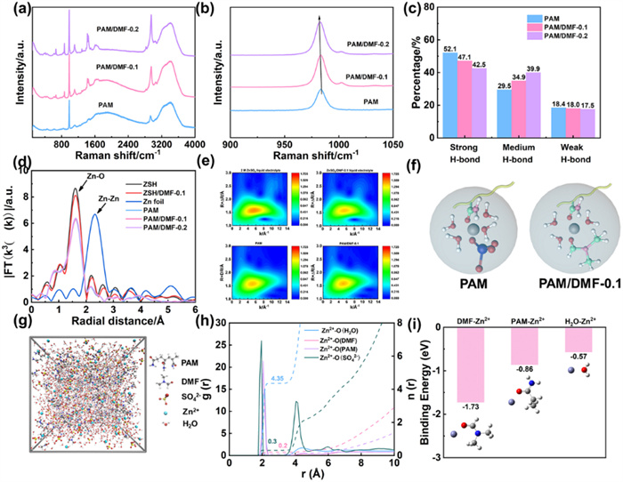
To reveal the effect of DMF on the solvation structure, Raman spectra were firstly conducted under the range of 100–4000 cm-1 (Fig. 2a). The appearance of the C—C, C=O and C—N stretching were also confirmed from the peaks of 1350–1650 cm-1 [33]. And the distinguished peak locate at around 980 cm-1 was related to the stretching vibration of SO42- and could be assigned into solvent-separated ion pairs (SSIP) and contact ion pairs (CIP) [34]. Fig. 2b showed a red shift of v(SO42-) in PAM/DMF hydrogel, indicating relative content of CIP decreased and the amount of SO42- in the first solvation shell was reduced, which helped to suppress the formation of Zn4(SO4)4(OH)6·xH2O. Besides, the broad band ranged from 3000–3800 cm-1 was corresponding to the stretching vibration of O—H, including strong H-bond (3260 cm-1), medium H-bond (3425 cm-1) and weak H-bond (3546 cm-1) [28,35]. As shown in Fig. 2c and Fig. S4 (Supporting information), the water activity in the hydrogel electrolyte could be fitted and compared by the relative content of various H-bond. Compared to pure PAM hydrogel, the content of strong H-bond decreased from 52.1% to 29.5% (PAM/DMF-0.1) and 18.4% (PAM/DMF-0.2). This result provided the evidence for anchored free water by DMF additive, enabling fewer side reactions.
Figure 2
Figure 2.
(a) Raman spectra of PAM, PAM/DMF-0.1 and PAM/DMF-0.2 hydrogels range from 100–4000 cm-1. (b) Raman spectra of characteristic peak of v(SO42-). (c) Relative intensity of strong, medium and weak H-bond in various hydrogel electrolyte. (d) EXAFS results of liquid electrolytes, hydrogel electrolytes and standard sample in R-space. (e) Wavelet transition of various electrolytes for the k3-weighted EXAFS signals. (f) Schematic diagrams of solvation structures of Zn2+ in different gel electrolytes. (g) Snapshot of the MD simulation results for the Zn2+ solvation shell of PAM/DMF-0.1 electrolyte. (h) RDF of Zn2+ obtained from MD simulation results. (i) Binding energies of Zn2+-H2O, Zn2+-DMF, and Zn2+-PAM (segment) and their corresponding models.
Moreover, the detailed solvation structure of hydrogels was revealed by X-ray adsorption spectroscopy (XAS), where Zn foil and 2 mol/L ZnSO4 liquid electrolyte (ZSH) were used as the standard. Pure PAM exhibited a different Zn-K adsorption edge compared with ZnSO4 liquid electrolyte while the adsorption edge of various hydrogels had no changes with DMF additive, indicating a change in the valence state of Zn after the introduction of PAM polymer (Fig. S5 in Supporting information). And the local coordination environments were investigated by the extended X-ray absorption fine structure (EXAFS) and wavelet transition (Figs. 2d and e). Although there were no obvious changes for the distance of Zn-O bond, the intensity of the first peak in PAM/DMF-0.1 was reduced compared to that of ZSH and ZSH/DMF-0.1, indicating DMF and PAM polymer participated in the solvation structure of Zn2+ and reduced the water molecules in the first solvent shell (Fig. 2f) [36,37].
Furthermore, molecular dynamics (MD) simulations were carried out to reveal the solvation structure (Figs. 2g and h, Fig. S6 in Supporting information). Compared with PAM hydrogel, DMF could displace water molecules in the first solvation shell. As shown in the radial distribution functions (RDFs), the coordination number of water decreased from 4.62 (PAM) to 4.35 (PAM/DMF-0.1), suggesting DMF could accelerate the de-solvation process of the Zn2+. And the coordination number of SO42- was decreased from 0.32 to 0.3, consistent with Raman result in Fig. 2b The accelerated de-solvation process could also be confirmed by calculating the activation energy (Ea) under the different temperature (303–343 K) (Fig. S7 in Supporting information). The PAM/DMF-0.1 showed a lower Ea of 45.23 kJ/mol than that of PAM (55.37 kJ/mol), reflecting enhanced reaction kinetics [38,39]. Density functional theory (DFT) calculation was further performed to analyze the interaction of Zn2+-H2O, Zn2+-SO42- and Zn2+-DMF. As depicted in Fig. 2i, DMF delivered highest binding energy (−1.73 eV) with Zn2+ compared to that of PAM (−0.86 eV) and H2O (−0.57 eV), easier to coordinate with Zn2+ and promote de-solvation process [40,41].
The ionic conductivity of the hydrogel electrolyte was firstly evaluated by stainless steel (SS) symmetric battery from electrochemical impedance spectroscopy (EIS). And the results were shown in Fig. S8 (Supporting information). As expected, the introduction of polar aprotic solvent (DMF) would limit the free water and sluggish the ion transport at the same time. Thus, the PAM/DMF exhibited the decreased ionic conductivities of 14.3 mS/cm (PAM/DMF-0.1) and 7.5 mS/cm (PAM/DMF-0.2). The electrochemical stability window (ESW) of the hydrogel electrolytes was also compared using linear sweep voltammetry (LSV) in Fig. S9 (Supporting information). Compared with PAM hydrogel (2.67 V), the ESW of the PAM/DMF systems was significantly broadened (PAM/DMF-0.1, 2.75 V; PAM/DMF, 2.78 V) due to the confinement of active water through H-bond between polar functional groups and water [25]. Meanwhile, water retention ability was improved after increasing the content of DMF in PAM hydrogel (Fig. S10 in Supporting information). Under 25 ℃ and 30% humidity, the weight of PAM/DMF (−0.1/0.2) systems held a retention above 59% after 16 h and remained 49%/52% after 72 h. In contrast, the weight of PAM hydrogel decreased rapidly within 6 h and dropped to 37% at the end. Considering the balance of ionic conductivity an ESW, PAM/DMF-0.1 was optimal to provide the ideal electrochemical performance.
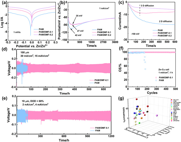
The anti-corrosion performance of Zn anode based on various hydrogel electrolytes was assessed by Tafel tests (Fig. 3a). The corrosion potential of PAM/DMF-0.1 (15 mV vs. Zn/Zn2+) was found a positive shift compared to that of PAM electrolyte (−0.12 mV vs. Zn/Zn2+), indicating that DMF additive could effectively decrease the corrosion rate. Subsequently, nucleation overpotentials of different hydrogel electrolytes were investigated by applying constant current (1 mA/cm2, 3600 s). As shown in Fig. 3b, the Zn//Zn cell with the PAM/DMF-0.1 electrolyte possessed a lower nucleation overpotential (27 mV) than that of PAM (42 mV), delivering a lower energy barrier for uniform nucleation [36]. Likewise, the cyclic voltammetry (CV) results of the Zn-Cu cells based on various PAM hydrogel delivered a decreased nucleation overpotential after introduction of the DMF additive (Fig. S11 in Supporting information). And the high response current of PAM/DMF indicated higher electrochemical activity [42]. Moreover, chronoamperometry (CA) was employed to reveal the diffusion behavior of the Zn2+. After applying constant voltage (−150 mV) with 600 s, PAM/DMF-0.1 showed fast 2D diffusion process and reached to 3D diffusion after 150 s (Fig. 3c), enabling uniform deposition of Zn [43]. On the contrary, PAM exhibited continues 2D diffusion process with increased current, leading to the formation of dendrite.
Figure 3
Figure 3.
(a) Tafel curves of Zn electrode with various PAM hydrogel electrolytes. (b) Constant-current discharging results of Zn-Zn cells at 1 mA/cm2. (c) Chronoamperogram results of Zn-Zn cells with constant applied voltage of −150 mV. (d) Cycling performance of Zn-Zn cells at 30 mA/cm2@15 mAh/cm2. (e) Cycling performance of Zn-Zn cells at 2 mA/cm2@4 mAh/cm2. (f) CE of the Zn-Cu cell with different electrolytes at 1 mA/cm2@1 mAh/cm2. (g) Performance comparison of Zn electrode with based on PAM/DMF-0.1 with other reported advanced hydrogel electrolytes.
Furthermore, the reversibility of Zn electrode based on various PAM electrolyte was evaluated by Galvanostatic charge-discharge (GCD) test under different current density (Figs. 3d and e, Figs. S12 and S13 in Supporting information). The Zn-Zn cell using the PAM/DMF-0.1 electrolyte provided a long-term stability with lower voltage polarization over 4000 h at 0.5 mA/cm2@0.5 mAh/cm2 while the cell using PAM electrolyte faced short circuit by dendrite penetration within 700 h (Fig. S12). Notably, the Zn-Zn cells were conducted at high current density with high areal capacity (30 mA/cm2@15 mAh/cm2). Under the depth of discharging (DOD) of 26%, the Zn-Zn cells based on PAM-DMF-0.1 electrolyte could deliver an outstanding stability over 650 h, providing tolerance for high current (Fig. 3d). In comparison, the voltage of the Zn-Zn cell using PAM electrolyte showed violent fluctuation and failed within 80 h due to severe side reaction. To reduce the total weight of the full cell, reducing the weight of Zn anode was necessary. We also evaluated the cycling performance of Zn-Zn cells using ultra-thin Zn (10 µm) at 1 mA/cm2@1 mAh/cm2. As shown in Fig. S13, the Zn-Zn cells with PAM/DMF-0.1 electrolyte exhibited a satisfactory cycling stability over 1400 h compared to that of PAM (216 h). Even under the condition of high utilization of 2 mA/cm2@4 mAh/cm2 (DOD: 68%), benefiting from the robust interface and high adhesion of the hydrogel, the symmetric cells with PAM/DMF-0.1 electrolyte maintained excellent stability over 1200 h (Fig. 3e). The controlling cell with PAM experienced short circuit after 100 h. To further prove the stable interface after cycles, scanning electron microscope (SEM) were performed to evaluate the cycled anode morphology under different conditions (30 mA/cm2@15 mAh/cm2 and 4 mA/cm2@4 mAh/cm2). As shown in Fig. S14 (Supporting information), both of cycled Zn exhibited a dendrite-free surface with vertical deposition, which was relative to the growth of crystal plane (100). And the enlarged charging/discharging curves were provided for the last cycles. It could be found continuously increased voltage during the last 10/5 cycles of symmetric batteries, providing the evidence for the stable interface without “soft contact” behaviour [44,45]. The reversibility of Zn during plating/stripping process was also evaluated based on the Coulombic efficiency (CE) of the Zn-Cu cells. As depicted in Fig. 3f and Fig. S15 (Supporting information), using PAM/DMF-0.1 as electrolyte, the average CE of the Zn-Cu cell could reach 99.68% with lower voltage polarization (100 mV) for 500 cycles, while the Zn//Cu cell with PAM electrolyte displayed an obvious fluctuation with increased polarization (145 mV), failing rapidly in 170 cycles, proving the enhanced reversibility of Zn anode resulted from suppression of HER and fewer passivation products [46].
By comparing the current density, cycling lifetime and utilization of Zn anode with previous reported hydrogel electrolyte (Fig. 3g), PAM/DMF-0.1 electrolyte could provide remarkably advantage of electrochemical performance (PDMAPS [18]; DCHE [20]; ZIG-20 wt% [23]; CCH [29]; PAM+45%TRE [30]; Gel-PUZ [35]; DCG [43]; PCMS [47]; OR-PUU/PAM [48]; Zn-HA-Gel [49]; PAM-CS [50]; PAM-PAMPS-10PD [51]; BBA-S [52]; SCH-Zn [53]; C-PVA/PAN [54]), further highlighting the effectiveness of robust interface and modified solvation structure in improving the cycling stability of the Zn anode.
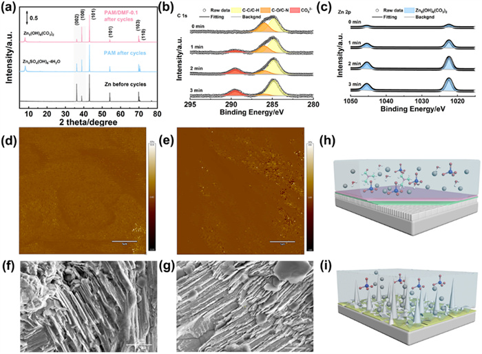
X-ray diffraction (XRD) was firstly conducted to investigate the surface products and crystal structure of Zn anode using various hydrogels before/after 100 cycles. As shown in Fig. 4a, the cycled Zn with PAM electrolyte presented obvious by-product Zn4SO4(OH)6·4H2O due to high content of free water. Instead, the XRD pattern of Zn electrode cycled with PAM/DMF-0.1 showed no peak of by-product and proved the evidence for the Zn5(OH)6(CO3)2, which was in situ formed inorganic SEI and served as the conductor for zinc ions [40,55]. Impressively, the peak intensity ratio between (100) and (002) could be further enhanced in PAM/DMF-0.1 electrolyte. The crystal orientation on the anode/electrolyte prefered to (100) plane, beneficial to achieve fast reaction kinetics and dense deposition [56-58]. The regulation mechanism on different Zn crystal planes was also proved by DFT calculations. Fig. S16 (Supporting information) showed that both of the adsorption energies of DMF/PAM on (100) plane were lower (−3.35 eV/−3.41 eV) than that of (002) plane (−0.78 eV/−0.79 eV), illustrating that the DMF/PAM possessed higher interaction with the (100) plane, slowing the deposition rate and endowing a dominated plane along the (100) [40,43], which was consistent with XRD results. Subsequently, in-depth X-ray photoelectron spectroscopy (XPS) by etching was performed to analyze the components of SEI on the cycled zinc surface. The C 1s and Zn 2p spectra results of cycled Zn with PAM/DMF-0.1 were shown in Figs. 4b and c. The peak intensity of organic compenents of C—O/C—N (286 eV) decreased gradually with increasing sputtering time, proving the exsitence of polymer in the external SEI layer. Meanwhile, the intensity of CO32- species locate at 289.5 eV and Zn-OH locate at 1022.4 eV/1045.5 eV increased and maintained stable, verifying the exsitence of Zn5(OH)6(CO3)2 in the internal layer of the SEI. As for cycled Zn with PAM electrolyte, the spectra of S 2p and Zn 2p were shown in Fig. S17 (Supporting information). It could be found that the content of SO42- (169 eV/170.2 eV) decreased and even vanished from the surface to interior, as well as the content of Zn-OH species, indicating the uneven distribution of Zn4SO4(OH)6·4H2O on the surface [59,60]. To prove the formation of Zn5(OH)6(CO3)2 during cycles, we firstly performed the ex-situ FT-IR to reveal the content change of CO32- on the anode/electrolyte interface which was shown in Fig. S18a (Supporting information). With the increased charging/discharging cycles (from 1st to 5th) of the symmetric battery, the peak intensity of the absorption band at 1507 cm-1 (CO32-) increased and finally kept stable, proving the in-situ formation Zn5(OH)6(CO3)2. Besides, to further explore the source of CO32- in forming inorganic SEI, we blowed the N2 into the electrolyte to reduce the CO2 content before polymerization. Then the surface product on the cycled Zn was also investigated by FT-IR test (Fig. S18b in Supporting information). It delivered a disappeared characteristic peak at the location of 1507 cm-1, indicating few formation of Zn5(OH)6(CO3)2. Therefore, the formation mechanism of Zn5(OH)6(CO3)2 could be proposed as follows: Initially, CO2 in air atmosphere was dissolved in electrolytes and transformed to H2CO3 (H2CO3 = H+ + HCO3-, HCO3- = H+ + CO32-). Subsequently, the DMF could decompose into formic acid and dimethylamine, by which further accelerating the conversion from HCO3- to CO32-, and CO32- species reacting with Zn2+/OH- to form Zn5(OH)6(CO3)2. This phenomenon was also reported in previous reference [40,55,61].
Figure 4
Figure 4.
(a) XRD results of the cycled Zn electrode in the Zn-Zn cell at 1 mA/cm2@1 h after 100 cycles. XPS results of (b) C 1s and (c) Zn 2p for cycled Zn electrode with PAM/DMF-0.1 electrolyte under the different sputter time; Average Young’s modulus of cycled Zn with (d) PAM/DMF-0.1 and (e) PAM electrolyte based on DMT model; SEM images of cycled Zn with (f) PAM/DMF-0.1 and (g) PAM electrolyte at 1 mA/cm2@1 h after 100 cycles. Schematic diagram of interfacial reaction mechanism with (h) PAM/DMF-0.1 and (i) PAM.
The interfacial modulus and fluctuation of cycled Zn with various hydrogels were revealed by atomic force microscopy (AFM). As decipted in Figs. 4d and e and Fig. S19 (Supporting information), due to the loose Zn4SO4(OH)6·4H2O on the bare surface, PAM electrolyte endowed a rigid interface with an average DMT modulus of 29.5 GPa and thus suffered from fracture by volumtric expansion, exhibiting a drastic roughness of 212 nm. In contrast, the polymer-inorganic SEI produced by PAM/DMF-0.1 electrolyte provided an average DMT Modulus of 8.6 GPa by combining the high modulus of Zn5(OH)6(CO3)2 and toughness of the polymer, achieving dense depostion with a slight roughness of 86 nm. This comparison highlighted the effectiveness of the bilayer SEI in accommodating volume expansion and promoting uniform depostion phsically [62,63]. Besides, interfacial adhesive strength was revealed by interfacial adhesive force on cycled Zn using AFM test. As shown in Fig. S20 (Supporting information), compared to pure PAM electrolyte (average: 1.62 nN), the cycled Zn with PAM/DMF electrolyte showed the increased interfacial adhesive force (average: PAM/DMF-0.2, 8.14 nN; PAM/DMF-0.1, 3.8 nN) as the cluster size increased, indicating the enhanced interfacial adhesion with larger cluster size [64,65]. The morphology of cycled Zn with various PAM hydrogels was also confirmed by scanning electron microscope (SEM), where the cycled Zn with PAM/DMF-0.1 electrolyte delivered a dense deposition along (100) plane with robust interface (Figs. 4f and h). By contrast, the dendrite went through passivation layer, resulting in broken interface and dendrite penetration (Figs. 4g and i). The interfacial compatibilty of anode/hydrogel was evaluated by EIS results of symmetric cells before/after 100 cycles (Fig. S21 in Supporting information). Filling by the polymer-inorganic SEI in situ formed in the charging/discharging cycles, the charge transfer resistance (Rct) of Zn-Zn cell with PAM/DMF-0.1 decreased from 610 ohm to 430 ohm while Rct of PAM increased from 1090 ohm to 1500 ohm, indicating the better contact and reduced interface inpedance.
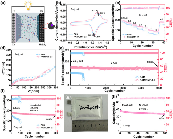
Finally, we assembled the full cells containing Zn anode and iodine cathode to demonstrate the practical values of PAM/DMF-0.1 electrolyte, and the structure diagram of Zn-I2 battery was shown in Fig. 5a. Iodine was pre-loaded into conductive carbon agent (Super P, SP) by typical gas-adsorption methods with a weight ratio of 35% (Fig. S22 in Supporting information). Comparing the CV curves of full cells using different PAM-based electrolytes (Fig. 5b), the PAM/DMF-0.1 electrolyte could deliver a higher reduction potential (1.26 V), larger current response and smaller polarization (ΔE = 0.07 V) compared to that of PAM electrolyte (1.23 V, ΔE = 0.13 V), reflecting the higher output voltage and faster reaction kinetics [66]. Moreover, rate performance of the full cells was shown in the Fig. 5c and the GCD profiles were given in Fig. S23 (Supporting information). The full cell with PAM/DMF-0.1 electrolyte provided a higher initial specific capacity of 197.9 mAh/g at 0.2 A/g (184.8 mAh/g for PAM) and maintained 85.1 mAh/g at 3 A/g (60.4 mAh/g for PAM), demonstrating high-rate performance excellent reversibility due to compatibility of PAM/DMF-0.1 electrolyte. This result was also confirmed by the lower Rct (168 ohm) of the full cell compared to that of PAM electrolyte (242 ohm) (Fig. 5d). For the long-term cycling stability, the full cells with different PAM electrolytes were evaluated at 2 A/g for 5000 cycles. As shown in Fig. 5e, the full cell with PAM/DMF-0.1 electrolyte delivered an ideal capacity retention of 90.3% while the full cell with PAM showed a decreased capacity and failed rapidly, proving the positive effect on inhibiting dendrite formation and anode corrosion. We further increased the utilization of Zn anode by employing ultra-thin Zn foil (10 µm) and higher mass loading of the iodine (8.64 mg/cm2). And the capacity ratio of negative electrode/positive electrode (N/P) was calculated as 4.3. When cycled at 0.2 A/g, the full cell with PAM/DMF-0.1 electrolyte could provide an initial capacity of 1.8 mAh and achieved an impressive capacity retention of 86.4% over 500 cycles (Fig. 5f in Supporting information), ascribed to superior interfacial stability. Furthermore, we assembled the single-layered pouch cell (4 × 6 cm) using ultra-thin Zn foil and high-loading iodine cathode (10 mg/cm2) (Figs. 5g and h, Fig. S24 in Supporting information). After 100 cycles, a maximum capacity (42 mAh, Fig. S25 in Supporting information) and volumetric energy density (30.7 Wh/L) were achieved in the pouch cell using PAM/DMF-0.1 electrolyte with a capacity retention of 85.2%, highlighting the feasibility to promote the practical application of AZIBs.
Figure 5
Figure 5.
(a) Schematic structure of Zn-I2 battery with hydrogel electrolyte. (b) CV curves of the full cells with PAM and PAM/DMF-0.1 electrolyte at 0.2 mV/s. (c) Rate performance of the full cells with various hydrogel electrolytes. (d) EIS results of the full cells; (e) Long-term GCD test of full cells at 2 A/g. Zn thickness: 100 µm. (f) Cycling stability of the full cells at 0.2 A/g using ultra-thin Zn (10 µm). (g) Optical images of pouch cell; (h) Cycling stability of the pouch cell at 0.2 A/g.
In summary, we constructed a polymer-inorganic SEI by introducing DMF additive to PAM hydrogel which could enhance the stability and compatibility of the anode/electrolyte interface. The well-designed bilayer SEI not only provided high interfacial modulus from internal layer to restrict the dendrite physically, but also accommodate volume expansion via toughness of external polymer during cycles. And the shear strength and interfacial adhesion strength were improved by larger polymer clusters. Additionally, DMF and polymer could regulate the crystal orientation by specific adsorption and modify the solvation structure of Zn2+, markedly promoting the dense deposition and suppressing the HER with fewer passivation product. As a result, the modified hydrogel electrolyte enabled the Zn-Zn cell with a long cycling lifetime (0.5 mA/cm2, 4000 h) and high tolerance for high current (30 mA/cm2, 650 h). Importantly, a high utilization (68%) based on ultra-thin Zn (10 µm) was achieved with excellent cycling stability (1200 h). Furthermore, the assembled Zn-I2 cells could deliver high capacity and high-capacity retention for long-term cycles. This work provides a feasible strategy to modify hydrogel electrolyte and construct stable Zn anode in AZIBs.
Declaration of competing interest
The authors declare that they have no known competing financial interests or personal relationships that could have appeared to influence the work reported in this paper.
This work was supported by the National Natural Science Foundation of China (No. 52471229), the Program for the Development of Science and Technology of Jilin Province, China (No. 20250205055GH) and Fundamental Research Funds for the Central Universities (No. 2025MS014). We greatly thank the 4B9A, Beijing Synchrotron Radiation Facility (https://cstr.cn/31109.02.BSRF.4B9A) for providing technical support and assistance in XAFS data collection.
Supplementary materials
Supplementary material associated with this article can be found, in the online version, at doi:10.1016/j.cclet.2025.111754.
Figure 1
(a) Schematic of the preparation process of various PAM hydrogels. (b) Optical images of the PAM/DMF-0.1 hydrogel before/after UV radiation. (c) FT-IR spectra of various PAM hydrogels/monomer/DMF. (d) Tensile stress–strain curves of various PAM hydrogels. (e) Shear strength of various samples. (f) SEM images of PAM/DMF-0.1 hydrogel. (g) DLS analysis for the hydrodynamic size distribution of the polymer clusters in quasi-solid electrolyte.
Figure 2
(a) Raman spectra of PAM, PAM/DMF-0.1 and PAM/DMF-0.2 hydrogels range from 100–4000 cm-1. (b) Raman spectra of characteristic peak of v(SO42-). (c) Relative intensity of strong, medium and weak H-bond in various hydrogel electrolyte. (d) EXAFS results of liquid electrolytes, hydrogel electrolytes and standard sample in R-space. (e) Wavelet transition of various electrolytes for the k3-weighted EXAFS signals. (f) Schematic diagrams of solvation structures of Zn2+ in different gel electrolytes. (g) Snapshot of the MD simulation results for the Zn2+ solvation shell of PAM/DMF-0.1 electrolyte. (h) RDF of Zn2+ obtained from MD simulation results. (i) Binding energies of Zn2+-H2O, Zn2+-DMF, and Zn2+-PAM (segment) and their corresponding models.
Figure 3
(a) Tafel curves of Zn electrode with various PAM hydrogel electrolytes. (b) Constant-current discharging results of Zn-Zn cells at 1 mA/cm2. (c) Chronoamperogram results of Zn-Zn cells with constant applied voltage of −150 mV. (d) Cycling performance of Zn-Zn cells at 30 mA/cm2@15 mAh/cm2. (e) Cycling performance of Zn-Zn cells at 2 mA/cm2@4 mAh/cm2. (f) CE of the Zn-Cu cell with different electrolytes at 1 mA/cm2@1 mAh/cm2. (g) Performance comparison of Zn electrode with based on PAM/DMF-0.1 with other reported advanced hydrogel electrolytes.
Figure 4
(a) XRD results of the cycled Zn electrode in the Zn-Zn cell at 1 mA/cm2@1 h after 100 cycles. XPS results of (b) C 1s and (c) Zn 2p for cycled Zn electrode with PAM/DMF-0.1 electrolyte under the different sputter time; Average Young’s modulus of cycled Zn with (d) PAM/DMF-0.1 and (e) PAM electrolyte based on DMT model; SEM images of cycled Zn with (f) PAM/DMF-0.1 and (g) PAM electrolyte at 1 mA/cm2@1 h after 100 cycles. Schematic diagram of interfacial reaction mechanism with (h) PAM/DMF-0.1 and (i) PAM.
Figure 5
(a) Schematic structure of Zn-I2 battery with hydrogel electrolyte. (b) CV curves of the full cells with PAM and PAM/DMF-0.1 electrolyte at 0.2 mV/s. (c) Rate performance of the full cells with various hydrogel electrolytes. (d) EIS results of the full cells; (e) Long-term GCD test of full cells at 2 A/g. Zn thickness: 100 µm. (f) Cycling stability of the full cells at 0.2 A/g using ultra-thin Zn (10 µm). (g) Optical images of pouch cell; (h) Cycling stability of the pouch cell at 0.2 A/g.

 DownLoad:

 下载:
下载:


 下载:
下载:
