 图1
X-ray diffraction patterns of neat PVDF and ST/PVDF composite films
Figure1.
X-ray diffraction patterns of neat PVDF and ST/PVDF composite films
图1
X-ray diffraction patterns of neat PVDF and ST/PVDF composite films
Figure1.
X-ray diffraction patterns of neat PVDF and ST/PVDF composite films
Citation:
SUI Yan, ZHOU Kai-Hao, HUANG Jian-Gen, ZHU Ying, ZENG Gui-Bing, OUYANG Shu-Xia. Enhanced Dielectric and Ferroelectric Properties of Core-Shell Structure of SrTiO3/PVDF Composite Films Cross-Linked with Silane Coupling Agent[J]. Chinese Journal of Inorganic Chemistry,
2017, 33(11): 2024-2030.
doi:
10.11862/CJIC.2017.231

核-壳结构的硅烷偶联剂交联的SrTiO3/PVDF复合物薄膜的铁电和介电性能
摘要:
通过溶液浇筑法制备了核-壳结构的硅烷偶联剂3-氨丙基三乙氧基硅烷(3-APTS)交联的SrTiO3/PVDF复合物薄膜,对其进行了XRD、FTIR、TG、DSC、SEM、介电和铁电性能测试。研究发现,使用硅烷偶联剂有助于SrTiO3在复合物薄膜中实现均匀分散,其可能与硅烷偶联剂可以被用作交联剂连接聚合物和无机材料形成核-壳结构有关。SrTiO3(ST)的引入有助于提高复合物薄膜的结晶性,但是会导致电活性β-晶相含量的轻微减少。当ST的质量含量达到30%时,复合物薄膜的介电常数可以增大至纯PVDF的2.5倍,并且不会引起介电损耗的明显增加;同时,该复合物薄膜的剩余极化率(Ps)也可以增大到原来的2倍左右。我们的研究表明,在PVDF中引入硅烷偶联剂表面改性的ST是制备具有良好分散性的复合物薄膜以及提升其铁电和介电性能的一种有效方法。
English
Enhanced Dielectric and Ferroelectric Properties of Core-Shell Structure of SrTiO3/PVDF Composite Films Cross-Linked with Silane Coupling Agent
Abstract:
Core-shell structure of SrTiO3/PVDF composite films cross-linked with silane coupling agent 3-aminopropyltriethoxysilane (3-APTS) were prepared by solution casting method and characterized by XRD, FTIR, TG, DSC, SEM, dielectric and ferroelectric test. SrTiO3 (ST) can be homogeneously distributed into PVDF matrix without obvious agglomeration in the presence of silane coupling agent, which may be related to the formation of core-shell structure in which 3-APTS acts as a cross-linker between polymer and inorganic material. The introduction of ST is helpful to improve the crystallinity, but will lead to a slight decrease in the electroactive β-phase content of composite films. The dielectric constant of composite film will increase up to 2.5 times larger than that of neat PVDF when the mass content of ST is up to 30%, and without leading to obvious increase of dielectric losses. Meanwhile, the Ps value of this film is increased up to about two times larger than that of pure PVDF. Our study suggests that the incorporation of surface modified ST into PVDF matrix is a useful way to obtain well dispersed film and improve its dielectric and ferroelectric property.
-
Key words:
- poly(vinylidene fluoride)
- / composite films
- / SrTiO3
- / dielectric
- / ferroelectric
-
Poly(vinylidene fluoride) (PVDF) has been a widely studied polymer due to its ferroelectric, piezoelectric and pyroelectric properties[1-5]. PVDF has at least four different polymorphs, including the non-polar α-phase and the polar β, γ and δ phases[6-7], in which polar β-phase with all the fluorine atoms located on the same side of PVDF chains is of most interest, because it has a much higher polarity than other phases, therefore the highest piezo, pyroelectric and ferroelectric activities[8-9]. But PVDF is usually limited by its low dielectric constant, in the application fields of electronic and electrical systems for energy pulse and power conditioning. In order to solve this problem, one of methods is to incorporate ferroelectric ceramics (such as BaTiO3, BaxSr1-xTiO3, Pb(Zr, Ti)O3) with high dielectric constant into PVDF matrix[10-11]. However, high volume fraction (>50%, V/V) of ceramics will always have to be used, which suffering from the drawback of poor dispersion[12]. Insoluble inorganic ceramics are usually difficult to be homogeneously dispersed into PVDF matrix, even in nano-scale. How to separate insoluble inorganic ceramics into PVDF matrix is still a challenge.
In this study, silane coupling agent 3-amino-propyltriethoxysilane (3-APTS) was used to help the dispersion of insoluble SrTiO3 (ST) into PVDF matrix. 3-APTS could act as a cross-linker between polymer and inorganic material to form a core-shell structure, in which SrTiO3 is the "core" and PVDF is the "shell". SrTiO3 is a well known paraelectric material with versatile technological applications for its interesting physical properties[13-14], but it is rarely used as the filler of PVDF[15-16]. The paraelectric material may provide a relatively high dielectric constant while eliminating the remnant polarization of the composites. The present work involves the fabrication of ST/PVDF composite films and the influence of ST upon the structure, crystallinity, thermal stability, dielectric and ferroelectric properties.
1 Experimental
1.1 Materials
All the chemicals used in this reaction were analytical grade and used as purchased from Shanghai Adamas Reagent Co., Ltd (Shanghai, China). PVDF

1.2 Characterization
X-ray diffraction (XRD; Bruker D8 Advance System, Germany) was performed at room temperature with Cu-target Kα radiation (λ=0.154 nm) at 40 kV and 40 mA over the 2θ range of 10°~40°. Fourier transform infrared spectroscopy (FTIR, Nicolet 6700, thermoscientific USA) was carried out over a range of 500~4 000 cm-1. The melting and crystallization behaviours of PVDF composite films were carried out on a differential scanning calorimeter DSC Q2000 TA Instruments. The sample was heated to 200 ℃ at a rate of 10 ℃·min-1 and held at 200 ℃ for 5 min, and then cooled to 30 ℃ at a rate of 10 ℃·min-1 to record the non-isothermal melting and crystallization behaviour. Complex dielectric permittivity was performed using automatic impedance TongHui 2828 Analyzer. The measuring AC voltage was 1 V. The electric hysteresis loops were recorded on a Ferroelectric Tester Multiferroic made by Radiant Technologies, Inc. For the dielectric measurement, the composite films were deposited with silver conducting glue on two opposite sides and extended by copper wires. The morphologies were observed with field emission scanning electron microscope (FE-SEM) performed on JEOL JSM-6700F. Thermogravimetric analysis (TGA) was performed using a NETZSCH TG 209 F3 thermogravimetric analyzer.
1.3 Preparation of ST/PVDF composite films
PVDF powder was dissolved in DMF at 60 ℃ by magnetic stirring to yield a clear solution (10%, w/w). Certain amount of powdered ST (over 200 mesh) was treated in the solution of 3-APTS in ethanol/water (95:5, V/V) at 60 ℃ for 2 h. The molar amount of 3-APTS is more than twice of ST. The ST suspension was added into above PVDF solution. The mixture solution was magnetic agitated at 60 ℃ for 3 h and ultra-sonicated for 1 h. Before casting, the mixture solution was degassed under vacuum overnight to eliminate the air bubbles. Subsequently, the solutions were cast on quartz glass substrates and incubated in an oven at 70 ℃ for 30 min to ensure the removal of solvent traces. Samples were denoted as ST5, ST10, ST15, ST20, ST25 and ST30 according to the mass content of ST in composite films.
2 Results and discussion
2.1 X-ray diffraction analysis
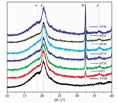
It is a usual method to determine the crystalline phase of PVDF matrix by X-ray diffraction. Fig. 1 shows the X-ray diffraction patterns of neat PVDF and ST/PVDF composite films. All the samples exhibit a strong crystalline peak at 2θ=20.4° assigned to polar β-phase and a weak peak at 18.6° assigned to non-polar α-phase[17-19], which indicates that they are β-phase dominated. With the addition of ST, a tiny peak appearing at 2θ=36.4° further confirmed the nucleation of β-phase[20]. With the increase in ST content, a peak at 2θ=32.4° corresponding to the characteristic peak of ST becomes more and more obvious, indicating the presence of ST in composite films. It can also be noticed that the intensity of α-phase characteristic peak (2θ=18.6°) has a little increase with the inclusion of ST, which means that the introduction of ST may lead to a slight decrease in the electroactive β-phase content.
图1
X-ray diffraction patterns of neat PVDF and ST/PVDF composite films
Figure1.
X-ray diffraction patterns of neat PVDF and ST/PVDF composite films
2.2 FTIR spectra analysis
Fig. 2A is the FTIR spectra of PVDF and ST/PVDF composite films. According to the reported data[21-22], the vibration band at 840 cm-1 (CH2 rocking and CF2 asymmetric stretching vibration) should be assigned to β-phase, whereas the vibration band at 763 cm-1 (CF2 bending and skeletal bending) should be ascribed to α-phase. As shown in Fig. 2A, the intensity of vibration band at 840 cm-1 representing β-phase is very high, whereas the vibration band at 763 cm-1 assigned for α-phase is almost invisible, which indicates that all the samples are β-phase dominated. This is consistent with the result obtained from X-ray diffraction analysis. It is normal that neat PVDF is β-phase dominated when the solution casting temperature is below 80 ℃[23]. In addition, a broad peak appears at 3 600~3 200 cm-1 with the incorporation of ST, which indicates that there should have strong hydrogen bond interactions in composite films.
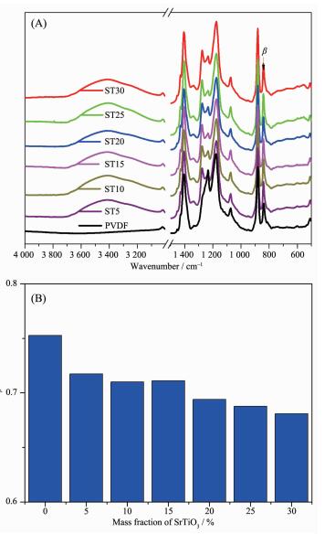 图2
FTIR spectra (A) and the calculated β-phase fraction (B) of PVDF and ST/PVDF composite films
Figure2.
FTIR spectra (A) and the calculated β-phase fraction (B) of PVDF and ST/PVDF composite films
图2
FTIR spectra (A) and the calculated β-phase fraction (B) of PVDF and ST/PVDF composite films
Figure2.
FTIR spectra (A) and the calculated β-phase fraction (B) of PVDF and ST/PVDF composite films
According to the reported method[24], the relative amounts of β-phase in crystalline PVDF matrix can be quantified with equation (1):
Here Fβ represents the relative mass fraction of the β-phase, Aα and Aβ are the absorbance at 763 cm-1 and 840 cm-1 corresponding to the α- and β-phases, respectively. As shown in Fig. 2B, the calculated result shows that Fβ value gradually decreases with the increase in ST content in PVDF matrix. This is also consistent with the X-ray diffraction analysis results. The addition of ST may slightly slow down β-phase crystallization process.
2.3 TG and DSC analysis
Fig. 3 shows TG curves of neat PVDF and ST/PVDF composite films. The introduction of ST has no obvious influence upon their thermal stability, but leads to a faster weight loss process before 450 ℃, which may be related to the gradually decomposing of silane coupling agent.
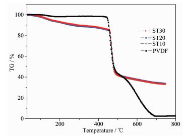 图3
TG curves of PVDF and ST/PVDF composite films
Figure3.
TG curves of PVDF and ST/PVDF composite films
图3
TG curves of PVDF and ST/PVDF composite films
Figure3.
TG curves of PVDF and ST/PVDF composite films
Fig. 4 shows the heating and cooling DSC curves of PVDF and ST/PVDF composite films. These reversible peaks should be related to the melting and crystallization process, respectively. The melting peak temperature (Tm) of neat PVDF is 157.8 ℃, and it increases up to 162~164 ℃ with the addition of ST. The crystallization temperature (Tc) of neat PVDF is 132.8 ℃, and it has a little increase after the addition of ST. This difference may be related to the initial crystallinity of samples. According to the reported method[25], the crystallinity can be calculated based on the following equation (2):
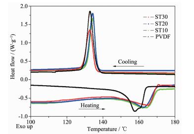 图4
DSC curves of PVDF and ST/PVDF composite films
Figure4.
DSC curves of PVDF and ST/PVDF composite films
图4
DSC curves of PVDF and ST/PVDF composite films
Figure4.
DSC curves of PVDF and ST/PVDF composite films
Where ΔHc is the melting heat of samples, is the weight percentage of ST in PVDF matrix, ΔHc
$ \circleddash$ is the melting heat of 100% crystalline PVDF, which is 93.07 and 130.40 J·g-1 for pure α- and β-phase PVDF, respectively. ΔHc$ \circleddash$ =93.07Fα+103.40Fβ is used for the calculation (Fα=1-Fβ). The calculated results reveal that the crystallinity (Xc) of PVDF, ST10, ST20 and ST30 is 36.64%, 37.43%, 42.00% and 51.46%, respectively. The gradually increasing crystallinity maybe related to the heterogeneous nuclei effect with modified ST as nuclei centers.2.4 Morphology characterization
The dispersion state of ST in PVDF matrix was examined by SEM. As shown in Fig. 5, ST was homogeneously dispersed into PVDF matrix without obvious agglomeration in the presence of 3-APTS. PVDF exhibits as large amount of spheres with the diameter varied from 5 to 8 μm, which is also the characteristic of β-phase, because α- and γ-phase dominated PVDF usually have diameter greater than 10 μm[26-27]. In order to investigate the influence of 3-APTS, another experiment was done under the same condition but without using 3-APTS, and the film was denoted as ST30* when 30% of ST was used. The SEM images of ST30* were given in Fig. 6. Obviously, ST cannot be well separated into PVDF matrix without the participation of 3-APTS. Not only the agglomeration can be found, but also the border of sphere becomes indistinct. The improvement of dispersion state in the presence of 3-APTS should be related to the formation of core-shell structure.
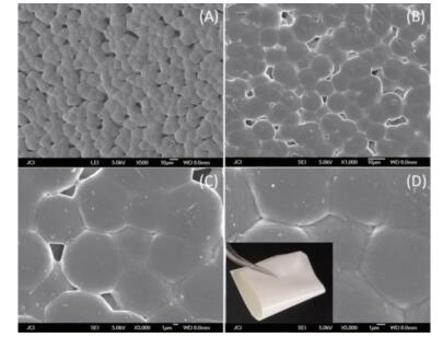 图5
SEM images of ST30 with magnification times of 500, 1 000, 3 000 and 5 000 respectively for A, B, C and D
Figure5.
SEM images of ST30 with magnification times of 500, 1 000, 3 000 and 5 000 respectively for A, B, C and D
图5
SEM images of ST30 with magnification times of 500, 1 000, 3 000 and 5 000 respectively for A, B, C and D
Figure5.
SEM images of ST30 with magnification times of 500, 1 000, 3 000 and 5 000 respectively for A, B, C and D
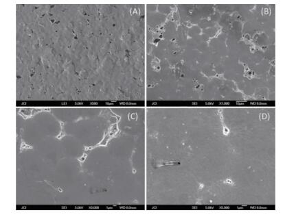 图6
SEM images of ST/PVDF composite film (ST30*) without using 3-APTS with magnification times of 500, 1 000, 3 000 and 5 000 respectively for A, B, C and D
Figure6.
SEM images of ST/PVDF composite film (ST30*) without using 3-APTS with magnification times of 500, 1 000, 3 000 and 5 000 respectively for A, B, C and D
图6
SEM images of ST/PVDF composite film (ST30*) without using 3-APTS with magnification times of 500, 1 000, 3 000 and 5 000 respectively for A, B, C and D
Figure6.
SEM images of ST/PVDF composite film (ST30*) without using 3-APTS with magnification times of 500, 1 000, 3 000 and 5 000 respectively for A, B, C and D
2.5 Proposed structure
As known, 3-aminopropyltriethoxysilane (3-APTS) can be used to couple polymer and inorganic filler through active amino and ethoxy groups to improve its adhesive, mechanical, electrical property and so on. For ST/PVDF composite films, the proposed core-shell structure is shown in Fig. 7. The silane coupling agent 3-APTS seems like a linker between ST and PVDF. At one end of 3-APTS, three ethoxy groups is hydrolyzed and linked with ST through Si-O-Ti or Si-O-Sr bonds; At the other end, the amino group is penetrated into PVDF matrix through N-H…F hydro-gen bond interactions. Some evidence can also be found from FTIR spectra. There are broad peaks at 3 600~3 200 cm-1 just appeared after the addition of ST, which should be N-H…F hydrogen bond interactions. The interaction between ST and 3-APTS can also be confirmed by the observation of Ti-O-Si vibration band (about 960 cm-1)[28-29].
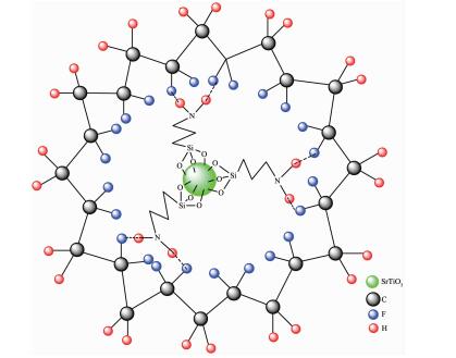 图7
Proposed core-shell structure of ST/PVDF composite films cross-linked with 3-APTS
Figure7.
Proposed core-shell structure of ST/PVDF composite films cross-linked with 3-APTS
图7
Proposed core-shell structure of ST/PVDF composite films cross-linked with 3-APTS
Figure7.
Proposed core-shell structure of ST/PVDF composite films cross-linked with 3-APTS
2.6 Dielectric properties
The temperature-dependent dielectric properties are investigated and shown in Fig. 8A and Fig. 8B. As shown in Fig. 8A, the dielectric constants gradually increase with the addition of ST. When ST content is up to 30%, the dielectric constant increases up to 22.1 at room temperature, which is about 2.5 times larger than that of neat PVDF (8.7). With temperature increasing, the dielectric constant has a little increase before 140 ℃, then exhibit an obvious dielectric abnormal due to the melting phase transition of PVDF for all the samples. With the addition of ST, this dielectric abnormal becomes more and more obvious. This difference should be resulted from the strong interaction between ST and PVDF (such as N-H…F hydrogen bond), which will be weakened or destroyed for the melting phase transition. The dielectric losses still remain very low before 140 ℃ (Fig. 8B). These results indicated that the dielectric constants of PVDF films could be improved by incorporating ST modified with 3-APTS, without leading to obvious influence upon dielectric losses.
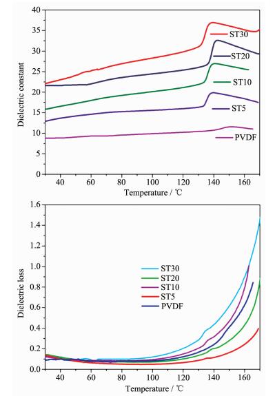 图8
Variable-temperature dielectric constants (A, top) and losses (B, bottom) of PVDF and ST/PVDF composite films
Figure8.
Variable-temperature dielectric constants (A, top) and losses (B, bottom) of PVDF and ST/PVDF composite films
图8
Variable-temperature dielectric constants (A, top) and losses (B, bottom) of PVDF and ST/PVDF composite films
Figure8.
Variable-temperature dielectric constants (A, top) and losses (B, bottom) of PVDF and ST/PVDF composite films
The frequency-dependent dielectric properties at room temperature are shown in Fig. 9A and Fig. 9B, respectively. The dielectric constants of ST/PVDF composite films gradually decrease with frequency increasing. This is mainly due to the reduction in the interfacial polarization (namely Maxwell-Wagner-Sillars effect) and space charge polarization. Interfacial polarization and space charge polarization mainly work in the low-frequency range due to their long relaxation time[30-31]. Fig. 9B shows that the dielectric losses still remain at low values.
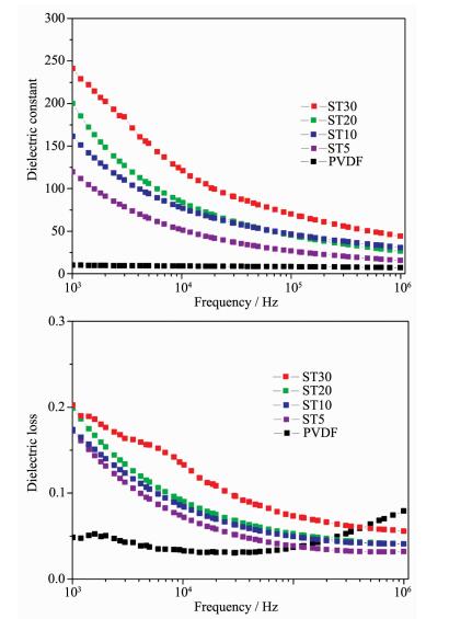 图9
Variable-frequency dielectric constants (A, top) and losses (B, bottom) of PVDF and ST/PVDF composite films
Figure9.
Variable-frequency dielectric constants (A, top) and losses (B, bottom) of PVDF and ST/PVDF composite films
图9
Variable-frequency dielectric constants (A, top) and losses (B, bottom) of PVDF and ST/PVDF composite films
Figure9.
Variable-frequency dielectric constants (A, top) and losses (B, bottom) of PVDF and ST/PVDF composite films
2.7 Ferroelectric properties
The ferroelectric behaviours of PVDF and ST/PVDF composite films are investigated and shown in Fig. 10. The ideal P-E loops obviously indicate the ferroelectric property. At the same electric field, ST/PVDF composite films exhibit better ferroelectric property than neat PVDF, which indicated that doping with ST modified with 3-APTS could also be a useful way to improve the ferroelectric properties of PVDF films. ST30 gives a spontaneous polarization (Ps) 11.5 μC·m-2 and Ec 32.9 kV·cm-1 at the electric field of 58.3 kV·cm-1. The Ps value of ST30 is about two times larger than that of pure PVDF.
 图10
P-E hysteresis loops of PVDF and ST/PVDF composite films at the same electric field
Figure10.
P-E hysteresis loops of PVDF and ST/PVDF composite films at the same electric field
图10
P-E hysteresis loops of PVDF and ST/PVDF composite films at the same electric field
Figure10.
P-E hysteresis loops of PVDF and ST/PVDF composite films at the same electric field
3 Conclusions
In summary, paraelectric ST modified with 3-APTS was homogeneously distributed into PVDF matrix to form a core-shell structure of ST/PVDF composite film. With the increase in ST content, the crystallinity of composite films was improved, but the β-phase content slightly decreased. The dielectric and ferroelectric properties could be significantly improved by incorporating paraelectric ST into PVDF.
-
-
[1]
Chu B, Zhou X, Ren K, et al. Science, 2006, 313:334-336 doi: 10.1126/science.1127798
-
[2]
Dang Z M, Yuan J K, Yao S H, et al. Adv. Mater., 2013, 25: 6334-6335 doi: 10.1002/adma.v25.44
-
[3]
Hao Y N, Wang X H, Brien S O, et al. J. Mater. Chem. C, 2015, 3:9740-9747 doi: 10.1039/C5TC01903F
-
[4]
Silva A B, Arjmand M, Sundararaj U, et al. Polymer, 2014, 55:226-234 doi: 10.1016/j.polymer.2013.11.045
-
[5]
Lu Y, Claude J, Neese B, et al. J. Am. Chem. Soc., 2006, 128:8120-8121 doi: 10.1021/ja062306x
-
[6]
Sun L L, Li B, Zhang Z G, et al. Eur. Polym. J., 2010, 46: 2112-2119 doi: 10.1016/j.eurpolymj.2010.09.003
-
[7]
Kar E, Bose N, Das S, et al. Phys. Chem. Chem. Phys., 2015, 17:22784-22798 doi: 10.1039/C5CP03975D
-
[8]
Ye H J, Yang L, Shao W Z, et al. RSC Adv., 2013, 3:23730-23736 doi: 10.1039/c3ra43966f
-
[9]
Yu S, Zheng W, Yu W, et al. Macromolecules, 2009, 42: 8870-8874 doi: 10.1021/ma901765j
-
[10]
Xia W M, Xu Z, Wen F, et al. Ceram. Int., 2012, 38:1071-1075 doi: 10.1016/j.ceramint.2011.08.033
-
[11]
Tiwari V, Srivastava G. Ceram. Int., 2015, 41:8008-8013 doi: 10.1016/j.ceramint.2015.02.148
-
[12]
Levi N, Czerw R, Xing S Y, et al. Nano Lett., 2004, 4:1267-1271 doi: 10.1021/nl0494203
-
[13]
刘剑, 谈国强, 苗鸿雁, 等.无机化学学报, 2009, 25(3):517-522 http://www.wjhxxb.cn/wjhxxbcn/ch/reader/view_abstract.aspx?flag=1&file_no=20090326&journal_id=wjhxxbcnLIU Jian, TAN Guo-Qiang, MIAO Hong-Yan, et al. Chinese J. Inorg. Chem., 2009, 25(3):517-522 http://www.wjhxxb.cn/wjhxxbcn/ch/reader/view_abstract.aspx?flag=1&file_no=20090326&journal_id=wjhxxbcn
-
[14]
展红全, 江向平, 李小红, 等.无机化学学报, 2015, 31(5):888-894 http://www.wjhxxb.cn/wjhxxbcn/ch/reader/view_abstract.aspx?flag=1&file_no=20150505&journal_id=wjhxxbcnZHAN Hong-Quan, JIANG Xiang-Ping, LI Xiao-Hong, et al. Chinese J. Inorg. Chem., 2015, 31(5):888-894 http://www.wjhxxb.cn/wjhxxbcn/ch/reader/view_abstract.aspx?flag=1&file_no=20150505&journal_id=wjhxxbcn
-
[15]
Guo Y Y, Guo Y J, Liu J M. J. Appl. Phys., 2012, 111: 074108(4Pages) 10.1063/1.3703070
-
[16]
Takesada M, Itoh M, Yagi T, et al. Ferroelectrics, 2003, 286: 3-8 doi: 10.1080/00150190390205889
-
[17]
Ma W, Zhang J, Wang X. Appl. Surf. Sci., 2008, 254:2947-2954 doi: 10.1016/j.apsusc.2007.10.037
-
[18]
Gregorio J R. J. Appl. Polym. Sci., 2006, 100:3272-3279 doi: 10.1002/(ISSN)1097-4628
-
[19]
Prabhakaran T, Hemalatha J. Mater. Chem. Phys., 2013, 137:781-787 doi: 10.1016/j.matchemphys.2012.09.064
-
[20]
Thakur P, Kool A, Bagchi B, et al. Phys. Chem. Chem. Phys., 2015, 17:1368-1378 doi: 10.1039/C4CP04006F
-
[21]
Bormashenko Y, Pogreb R, Stanevsky O, et al. Polym. Test., 2004, 23:791-796 doi: 10.1016/j.polymertesting.2004.04.001
-
[22]
Salimi A, Yousefi A A. Polym. Test., 2003, 22:699-704 doi: 10.1016/S0142-9418(03)00003-5
-
[23]
Martins P, Lopes A C, Lanceros-Mendez S. Prog. Polym. Sci., 2014, 39:683-706 doi: 10.1016/j.progpolymsci.2013.07.006
-
[24]
Yang L, Qiu J, Ji H, et al. Composites Part A, 2014, 65:125-134 doi: 10.1016/j.compositesa.2014.06.006
-
[25]
Costa P, Silva J, Sencadas V, et al. Carbon, 2009, 47:2590-2599 doi: 10.1016/j.carbon.2009.05.011
-
[26]
Mandal D, Henkel K, Schmeisser D. Mater. Lett., 2012, 73: 123-126 doi: 10.1016/j.matlet.2011.11.117
-
[27]
Ince-Gunduz B S, Alpern R, Amare D, et al. Polymer, 2010, 51:1485-1493 doi: 10.1016/j.polymer.2010.01.011
-
[28]
Zeitler V A, Brown C A. J. Phys. Chem., 1957, 61:1174-1177 doi: 10.1021/j150555a010
-
[29]
Zhuiykov S, Akbari M K, Hai Z, et al. Mater. Des., 2017, 120:99-108 doi: 10.1016/j.matdes.2017.02.016
-
[30]
Dang Z M, Wang H Y, Xu H P. Appl. Phys. Lett., 2006, 89: 112902(3Pages) http://ieeexplore.ieee.org/xpls/abs_all.jsp?arnumber=4822030
-
[31]
Zhou Y C, Bai Y Y, Yu K, et al. Appl. Phys. Lett., 2013, 102: 252903(5Pages) http://ieeexplore.ieee.org/xpls/abs_all.jsp?arnumber=6549089
-
[1]
-

Figure 2 FTIR spectra (A) and the calculated β-phase fraction (B) of PVDF and ST/PVDF composite films

Figure 5 SEM images of ST30 with magnification times of 500, 1 000, 3 000 and 5 000 respectively for A, B, C and D
Superior flexibility is demonstrated by a macroscopic image shown in the inset of D

Figure 6 SEM images of ST/PVDF composite film (ST30*) without using 3-APTS with magnification times of 500, 1 000, 3 000 and 5 000 respectively for A, B, C and D

Figure 7 Proposed core-shell structure of ST/PVDF composite films cross-linked with 3-APTS

Figure 8 Variable-temperature dielectric constants (A, top) and losses (B, bottom) of PVDF and ST/PVDF composite films

Figure 9 Variable-frequency dielectric constants (A, top) and losses (B, bottom) of PVDF and ST/PVDF composite films
-


 下载:
下载:


 扫一扫看文章
计量
- PDF下载量: 11
- 文章访问数: 1581
- HTML全文浏览量: 218
 下载:
下载:
