College of Chemistry and Chemical Engineering, Jiangxi Science and Technology Normal University, Nanchang 330013, China
b.
State Key Laboratory of Chemo/Bio-Sensing and Chemometrics, College of Chemistry and Chemical Engineering, Advanced Catalytic Engineering Research Center of the Ministry of Education, Hunan University, Changsha 410082, China
c.
Greater Bay Area Institute for Innovation, Hunan University, Guangzhou 511300, China
d.
KBC Hydrogen Energy Technology Co., Ltd., Yiyang 413100, China
* Corresponding authors. E-mail addresses: cshscu@163.com (S. Chen)
taoli@hnu.edu.cn (L. Tao). 1 These authors contributed equally to this work.
Received Date:
20 October 2024 Accepted Date:
11 December 2024 Revised Date:
29 November 2024 Available Online:
15 April 2026
Abstract:
Ruthenium, possessing a comparable metal-hydrogen bond energy to Pt, has emerged as a promising electrocatalyst for the hydrogen oxidation reaction (HOR), but its practical applications are hindered by susceptibility to deactivation or dissolution under operating conditions of fuel cells. Herein, graphene-encapsulated Ru nanoparticles (Ru@NG) was employed as the HOR catalyst for high-temperature polymer electrolyte membrane fuel cells (HT-PEMFCs). The graphene shells on the Ru can block effectively the surface adsorption of phosphoric acid in electrolyte and CO in anode fuel, but does not affect H2 free access to Ru sites, thus increase the activity expression and stability of catalysts under the high temperature, strong acid, and oxidation conditions of the HT-PEMFCs. With Ru@NG as the anode catalyst, the fuel cell delivers a peak power density of 760 mW/cm2 with pure H2, and additionally, it shows better tolerance to CO that the performance is 1.5 times that of the Pt/C catalysts with H2 fuel containing 1% CO. This work provides an alternative strategy to design the electrocatalysts for HT-PEMFCs.
Polymer electrolyte membrane fuel cells (PEMFCs) as a promising energy transfer device typically operate at 80 ℃, but the cost of high purity H2 is the main barrier for its large-scale commercialization [1-4]. High-temperature PEMFCs (HT-PEMFCs) employ phosphoric acid (PA) as the proton conduction and operate at 120–300 ℃, which could significantly decrease the fuel cost by directly utilize crude hydrogen as fuel [5]. Therefore, the development of high-performance HT-PEMFCs has great significance for boosting the development of the hydrogen energy industry [6,7].
HT-PEMFCs primarily employ PA as the proton transport conductor, but the strong adsorption of PA on the catalyst surface can block the contact of the reactants and the active sites, limiting the expression of catalytic activity [8,9]. This challenge can be addressed by regulating the electronic structure of catalysts, which can reduce the adsorption amount of PA on the catalyst surface and promote effectively the expression of catalytic activity; or by introducing co-catalysts, which can induce the transfer adsorbption of PA and enhance proton transport ability, boosting catalyst performance [10,11]. Furthermore, due to the elevated reaction temperature and rich PA environment, catalysts are prone to Oswald ripening deactivation. This can be mitigated by selecting more corrosion-resistant supports, thereby improving the stability of the HT-PEMFCs [12]. Ru metal has the similar energy of metal-hydrogen to Pt and is much cheaper than Pt, thus acting as a potential alternative to Pt-based catalysts [13-15]. Unfortunately, the strong adsorption of oxygen-containing species in electrolytes on Ru surfaces would reduce the active sites, leading to unsatisfactory catalytic performance [16]. Moreover, oxyphilic Ru is more easily transformed to amorphous ruthenium oxide under the oxidation potential, resulting in rapid inactivation of the catalytic performance of Ru-based electrocatalysts [16,17]. Especially during the start-up or shut-down processes of the fuel cells, the cell polarity reversal caused by H2 starvation would increase the anode potential [18,19].
These factors pose significant challenges to the application of Ru-based catalysts in HT-PEMFCs. Recently, our group by using characteristics of high temperature operating conditions of HT-PEMFCs has developed a series of high activity and stability catalysts, such as Pt/FeP/C, RuMo/C, Pd/C anode catalysts [20-22]. Moreover, we further developed coupled thermo-electrocatalytic system, combined the ethanol/methanol thermal catalysis with electrocatalysis based on Ru-, Pd-, Pt-, and Ir-based catalysts, realizing efficient production of hydrogen and other value-added chemicals [23-26]. These previous works provide new possibilities for the development of Ru-based catalysts under the high-temperature operating conditions of HT-PEMFCs.
In this work, graphene-encapsulated Ru nanoparticles (Ru@NG) were prepared via chemical vapor deposition, addressing effectually the issues of poor activity and stability of Ru as a catalyst for HT-PEMFCs (Fig. 1a). Ru nanoparticles (NPs) with graphene shells can not only regulate the energy of metal-hydrogen and block the surface adsorption of PA and CO, but also not affect H2 free access to Ru sites, thereby enhancing the activity and stability of the catalysts. The performance of HT-PEMFCs using Ru@NG as the anode catalyst exhibits comparable performance to commercial Pt/C catalyst, reaching a peak power density (PPD) of 760 mW/cm2. Furthermore, it shows higher output power when using hydrogen fuel containing CO. This work provides valuable insights for the development of high-efficiency catalysts in HT-PEMFCs.
Figure 1
Figure 1.
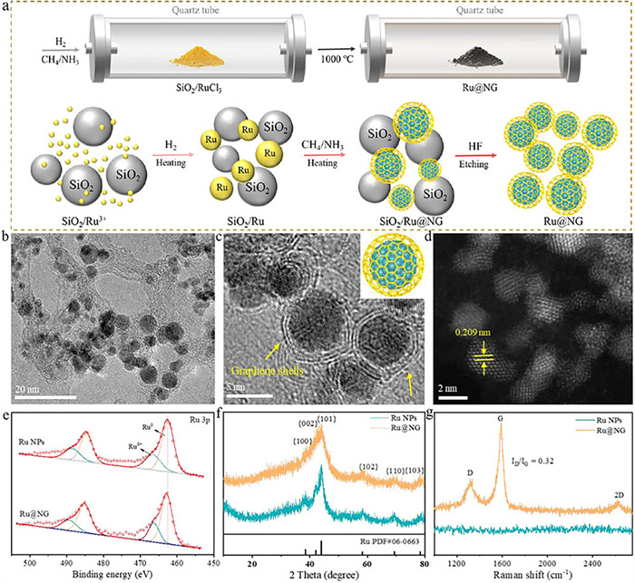
(a) Schematic showing preparation of graphene encapsulated Ru nanoparticles (Ru@NG). (b) TEM and (c) HR-TEM images of Ru@NG (Inset: schematic illustration of Ru@NG). (d) Atomic-resolution HAADF images of Ru@NG. (e) Ru 3p XPS, (f) XRD, and (g) Raman of Ru NPs and Ru@NG.
The synthesis details of Ru NPs and Ru@NG are given in supporting information. The Ru-based catalysts in this work were synthesized by chemical vapor deposition, as shown in Fig. 1b, the Ru NPs were obtained after high-temperature treatment and still exhibited well-dispersed with a uniform size about 3.2 nm. The high-resolution transmission electron microscopy (HR-TEM) analysis exhibits that the Ru NPs are coated by graphene shells and have 0.209 nm lattice spacing, the most of graphene shells on the Ru NPs contain only 1–2 layers (Figs. 1c and d). The morphology of Ru NPs is similar to Ru@NG except no coated graphene layers, the particle size and the lattice spacing of Ru NPs are ca. 3.2 and 0.206 nm, respectively (Fig. S1 in Supporting information). The EDS mappings of Ru@NG are shown in Fig. S1d, Ru, C and N elements are distributed homogeneously over whole catalysts, further indicating the formation of N-doped graphene shells.
X-ray photoelectron spectroscopy (XPS) was utilized to investigate the chemical states of those samples, as shown in Fig. 1e, the binding energies of Ru 3p3/2 at 462.8 eV and Ru 3p1/2 at 485.1 eV in Ru@NG were attributed to the presence of metallic Ru0, the doublet pairs at 466.4 and 489.5 eV were assigned to Ruδ+ of oxidation state, respectively [27-29]. The similar XPS features of Ru could also be obtained for Ru NPs, but the difference was that the overall Ru 3p spectra of Ru NPs shifted to the lower binding energy regions relative to that of Ru@NG. Such binding energy changes may cause by the N-doped graphene shells in Ru@NG, the N 1s peak for Ru@NG was deconvoluted into oxidized N (402.8 eV), graphitic N (401.0 eV), and pyridinic N (399.0 eV) (Fig. S2b in Supporting information), the presence of pyridinic N led to the strong electronic interaction between Ru and N-doped graphene shells. The electron-rich catalyst indicates fewer oxide species in the catalyst, which may result in better activity and stability. X-ray diffraction (XRD) spectra showed that both of Ru NPs and Ru@NG have characteristic peaks of Ru, which were in good agreement with the metallic Ru (PDF #06–0663) (Fig. 1f), a larger shoulder peak means Ru NPs in Ru@NG with smaller particle sizes. The Raman spectra for Ru@NG exhibited two characteristic peaks of D and G bands (Fig. 1g), this further confirmed the presence of the graphene shells. The D/G ratio of 0.32 indicates that the graphene shells on the Ru NPs has a better crystallinity and fewer defects, enabling better resistance to oxidation. Thermogravimetric analysis determined the relative content of the graphene shells under an air atmosphere, the weight of the Ru@NG sample decreased by around 32%, while the Ru NPs showed almost no change (Fig. S2a in Supporting information). Compared to the specific surface areas of Ru NPs (80.5 m2/g), that of Ru@NG reached 337.5 m2/g after Ru coated with graphene shells as calculated from nitrogen sorption isotherms (Fig. S3 in Supporting information).
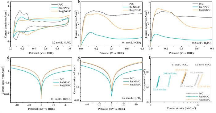
The cyclic voltammetry (CV) curves of the catalysts were performed in 0.2 mol/L H3PO4, a pair of redox peaks of Pt/C in the range of 0.4–0.75 V indicated the strong absorption of PA (Fig. 2a). The HOR activity of the catalysts was assessed by rotating disk electrode (RDE) at 1600 rpm with a scan rate of 10 mV/s in 0.1 mol/L HClO4 or 0.2 mol/L H3PO4 saturated with H2. HOR polarization curves in HClO4 for catalysts are shown in Fig. 2b, the HOR current density of the Ru@NG/C catalyst is higher than that of Ru NPs/C at any given potential and approaches to the performance of the commercial Pt/C catalyst. In addition, the same trend of HOR activity was found in H3PO4 (Fig. 2c), Ru@NG/C showed HOR performance indistinguishable from that of Pt/C, proving that exhibits excellent PA tolerance. To further investigate the HOR kinetics, polarization curves of the three catalysts were performed at various rotation rates ranging from 3600 rpm to 400 rpm, providing additional support for the two-electron pathway of the HOR (Fig. S4 in Supporting information) [30,31]. Moreover, the fitting HOR kinetic parameters using the Butler-Volmer (B-V) equation, the Tafel plots versus potential are shown in Figs. 2d and e, all the B-V plots exhibit a symmetric figure. Compared to Ru NPs/C, Ru@NG/C exhibited obviously higher current densities in HClO4 or H3PO4, due to its reaction kinetics much faster than those of Ru NPs/C. In HClO4 electrolyte, the HOR exchange current density of Ru@NG/C was slightly lower than that of commercial Pt/C, whereas the opposite result was obtained in H3PO4 environment (Fig. S5c in Supporting information). This phenomenon suggests that the nitrogen-doped graphene shells promoted H3PO4 tolerance and the HOR kinetic process of Ru-based catalysts in H3PO4 environment. The Tafel slopes of three catalysts were all higher than 118 mV/dec (Fig. 2f), indicating that the HOR processes follow the Volmer-Tafel mechanism, where the Volmer step is the rate-determining step, involving hydrogen dissociation [21,32]. Therefore, adjusting the binding energy of hydrogen on the catalysts could effectively improve the HOR reaction kinetics.
Figure 2
Figure 2.
(a) CV curve of Pt/C, Ru NPs/C, and Ru@NG/C in 0.2 mol/L H3PO4. HOR polarization curves of Ru@NG, Ru NPs/C, and Pt/C in H2-saturated 0.1 mol/L (b) HClO4 and (c) H3PO4, rotation rate: 1600 rpm, scan rate: 10 mV/s. B-V plots tested in 0.1 mol/L (d) HClO4 and (e) H3PO4. (f) Tafel plots of HOR in different electrolyte were tested with gas diffusion electrode.
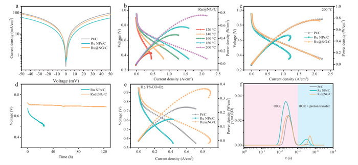
Membrane electrode assembly (MEA) of HT-PEMFCs was fabricated using PA doped polybenzimidazole (PBI) membrane as the polymer electrolyte, 2% PBI in the catalyst layer as the binder, 40 wt% Pt/C as the cathode, and three samples as the anode. The B-V plots of fuel cells also exhibit a symmetric figure, the HOR exchange current density of Ru@NG/C was higher than that of Ru NPs/C, following the Volmer-Tafel process (Fig. 3a). As shown in Fig. 3b, the HT-PEMFCs performance using Ru@NG/C as the anode catalyst exhibited that PPD was increased from 173 mW/cm2 to 760 mW/cm2 with increasing reaction temperature (120–200 ℃). The enhancement of fuel cell performance is attributed to the accelerated electrode reaction rate caused by the increased reaction temperature. Both of fuel cell performances of Pt/C and Ru NPs/C as anode catalysts also improved obviously after increasing reaction temperature (Fig. S6 in Supporting information). The fuel cell performances of Pt/C, Ru NPs/C, and Ru@NG/C as anode catalysts at 200 ℃ were shown for comparison, where PPD of Ru@NG/C reached 760 mW/cm2 and only 2 mW/cm2 lower than that of Pt/C (Fig. 3c). The linear relationship between reaction temperature and the PPD of Pt/C, Ru NPs/C, and Ru@NG/C was summarized in Fig. S6c, where Ru@NG/C showed a more significant slope than Pt/C across the entire temperature range of 120–200 ℃. The PPD increase amplitude of Pt/C and Ru@NG/C were 180% and 339%, respectively. In comparison to Ru NPs/C, Ru@NG/C exhibited both higher PPD and performance increase amplitude, further indicating that the nitrogen-doped graphene shells significantly improved the HOR performance of Ru-based catalysts in HT-PEMFCs.
Figure 3
Figure 3.
(a) B-V diagram in fuel cells at 200 ℃. (b) The fuel cell performance of the Ru@NG/C anode catalyst varies with reaction temperature. (c) Fuel cell performance diagram of Pt/C, Ru NPs/C, and Ru@NG/C at 200 ℃. (d) Durability comparison of Ru NPs/C and Ru@NG/C at 200 ℃. (e) Fuel cell performance of Ru@NG/C, Pt/C and Ru NPs/C anode catalysts at 160 ℃ in a mixed gas containing 1% CO. (f) Comparison of DRT of Pt/C, Ru NPs/C and Ru@NG/C at 200 ℃.
Stability is a vital factor in evaluating the practicability of a non-platinum catalyst of fuel cell. As displayed in Fig. 3d, Ru@NG/C displays much superior stability than that of Ru NPs/C. The fuel cell voltage of Ru@NG/C only decreases by 5.9% after a continuous 120 h operation at 0.8 A, while the voltage of Ru NPs/C decreases by 27% only after 25 h. Moreover, the PPD of Ru@NG/C (Fig. S7a in Supporting information) only decreased by 48 mW/cm2 while the PPD of Ru NPs/C decreased from 487 mW/cm2 to 153 mW/cm2, the decline is 334 mW/cm2 (Fig. S7b in Supporting information). The TEM images of Ru NPs/C and Ru@NG/C after the stability test are displayed in Fig. S8 (Supporting information), no obvious change and aggregation in Ru@NG/C is observed compared with the original sample, but occurring slight aggregation in Ru NPs/C. The XPS results of Ru 3p were also compared before and after the stability test, the relative content of Ru0 in Ru@NG/C is almost no degradation after over 120 h endurance test, while that in Ru NPs/C decreases 9% only after 25 h endurance test (Figs. S7c and d in Supporting information). These results reveal that the Ru encapsulated by graphene shells effectively protects the metal Ru from being oxidized to some degree, which explains the superior stability of Ru@NG/C.
The increased operation temperature can decrease the surface adsorption of catalysts and ease the CO poisoning of the electrocatalysts, the tolerance of high CO content of HT-PEMFCs is an indispensable factor. The CO tolerance of these anode catalysts was investigated at 160 ℃ under 1% CO/H2 atmosphere. The PPD of the Ru@NG/C decreased from 454 mW/cm2 to 355 mW/cm2, with a decline of only 22%, while the performances of Pt/C and Ru NPs/C decreased by 54% and 34%, respectively (Fig. 3e and Figs. S9a–c in Supporting information). The performance changes of three catalysts indicate that the CO tolerance of Ru@NG/C outperforms Pt/C and Ru NPs/C obviously under different CO concentration gradients (Fig. S9d in Supporting information). To further understand the cause of the improved HOR activity and exceptional anti-poisoning, CO-stripping tests of the catalysts were carried out at 160 ℃ in HT-PEMFCs. As shown in Fig. S9e (Supporting information), it was observed that the CO oxidation peak and onset potential of Ru@NG/C are located at 0.462 and 0.356 V, respectively. These values are also significantly lower than Ru NPs/C (0.481 V and 0.377 V) and Pt/C (0.657 V and 0.543 V), suggesting that the CO on the surface is easily oxidized, reducing the adsorption of CO on the surface and inhibiting the CO toxicity. The electrochemically active surface area (ECSA) of three catalysts were assessed and shown in Fig. S9f (Supporting information), Ru@NG/C exhibits the highest ECSA, arriving 445.89 m2/gmetal. The results show that the graphene shells can effectively reduce the adsorption of PA for constructing more electrocatalytic active surfaces.
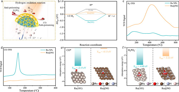
After analyzing the above preliminary results, we deduced that graphene shells on the Ru might screen PA and CO away from Ru surface excepting H2 (Fig. 4a). To shed light on the mechanism for the performance enhancement, the adsorption energies of H* on different sites in Ru@NG models were carried out through theoretical calculations. As shown in Fig. 4b, the Ru sites ((H*)Ru@NG) between Ru NPs and graphene shells exhibit the most reasonable hydrogen adsorption energy. Compared with the ΔGH* of Ru(101) (−0.49 eV) and N-Ru@NG (0.38 eV) (H* adsorbed on N sites of graphene shells), (H*)Ru@NG exhibits a superior ΔGH* of 0.17 eV, which is closer to the ideal value for hydrogen electrocatalysis [16]. Fig. 4c displays the adsorption peaks of H2 temperature-programmed desorption (H2-TPD) of Ru NPs and Ru@NG. A broad peak starting at 243 ℃ and ending at 780 ℃ in Ru@NG has a stronger binding energy than that of Ru NPs, which may be attributed to the local enrichment of H2 caused by increasing the specific surface area via the Ru coated with graphene shells. The suitable H2 adsorption strength in Ru@NG ensures the excellent HOR performance and is also consistent with the theoretical calculation results. Distribution of relaxation times (DRT) analysis of electrochemical impedance spectra (EIS) data in HT-PEMFCs were helpful to identifying kinetic processes occurring on different time scales, the short relaxation time region represented the proton transfer process and anodic HOR process (Fig. 3f and Fig. S11 in Supporting information). The HOR peak of Ru@NG/C located at lower relaxation time region with smaller integral area, indicated that the higher intrinsic HOR activity of Ru@NG/C catalyst promoted the performance of HT-PEMFCs rather than the mass transfer process affected by the structure of catalyst layer [21]. Moreover, (OH*)Ru@NG (−0.39 eV) shows the stronger hydroxyl adsorption than OH* on Ru(101) (−0.27 eV) (Fig. S13 in Supporting information), the OH* tends to occur the adsorption transfer from Ru(101) to carbon sites of graphene shells in Ru@NG, which will accelerate the OH* removal of Ru surface to expose more reactive sites. The adsorption energy of CO* on Ru@NG (−0.13 eV) is much lower than that of Ru(101) (−2.15 eV) (Fig. 4e). CO-TPD showed that Ru@NG has significantly lower CO adsorption strength and adsorption capacity, which is consistent with the better CO tolerance from experimental and calculated results (Fig. 4d). And the Eads(H2PO4-) (−2.22 eV) on Ru@NG surface is weaker obviously, which is consistent with the results observed in previous solution electrochemical and fuel cells experiments (Fig. 4f). Overall, interfacing Ru NPs with graphene shells will optimize selectively the adsorption of diverse intermediates, synergistically contributing to exceptional HOR performance, stability, and poison tolerance in high-temperature acid-rich conditions of HT-PEMFCs.
Figure 4
Figure 4.
(a) Schematic diagram of Ru@NG anti-poisoning during HOR in HT-PEMFCs. (b) H* absorbed energy at Ru(101), N—C/Ru@NG and Ru@NG models. (c) H2-TPD and (d) CO-TPD of Ru NPs and Ru@NG. The absorption energy of (e) CO* and (f) H2PO4- on Ru(101) and Ru@NG models.
In summary, uniformly distributed Ru NPs encapsulated by graphene shells is utilized as a high-stability anode catalyst against CO and PA toxicity for HT-PEMFCs. The graphene shells in Ru@NG construct limited transport channels, effectively reducing the surface adsorption energy of larger PA/CO molecules and suppressing its contact with Ru sites, thereby enabling excellent anti-poisoning ability. Moreover, smaller H2 can freely pass through graphene shells and contact with Ru sites directly, H* adsorption energy is also regulated by graphene shells and further influences the rate-determining step of the HOR, achieving the ultimate expression of activity. This work provides new guidance for designing the high-efficiency catalysts of HT-PEMFCs.
Declaration of competing interest
The authors declare the following financial interests/personal relationships which may be considered as potential competing interests: Li Tao reports financial support was provided by National Natural Science Foundation of China.
This work was supported by the National Key R&D Program of China (No. 2021YFA1500900), the National Natural Science Foundation of China (Nos. 22425021, 22102053, 22509056), and the Provincial Natural Science Foundation of Hunan (Nos. 2024JJ2012, 2024JJ6127, 2024JK2099), the Science and Technology Innovation Program of Hunan Province (No. 2022RC1036), Guangdong Basic and Applied Basic Research Foundation (No. 2024A1515012889), Changsha Municipal Natural Science Foundation (No. kq2208009), Shenzhen Science and Technology Program (No. JCYJ20210324122209025), Major Program of the Natural Science Foundation of Hunan Province (No. 2021JC0006), the Science Funds of the Education Office of Jiangxi Province (No. GJJ2201324), the Science Funds of Jiangxi Province (Nos. 20224BAB213018, 20242BAB25168), the China Postdoctoral Science Foundation (No. 2023M741121).
Supplementary materials
Supplementary material associated with this article can be found, in the online version, at doi:10.1016/j.cclet.2024.110754.
[1]
J. Zhang, D. Aili, S. Lu, et al., Research 2020 (2020) 9089405.
Figure 1
(a) Schematic showing preparation of graphene encapsulated Ru nanoparticles (Ru@NG). (b) TEM and (c) HR-TEM images of Ru@NG (Inset: schematic illustration of Ru@NG). (d) Atomic-resolution HAADF images of Ru@NG. (e) Ru 3p XPS, (f) XRD, and (g) Raman of Ru NPs and Ru@NG.
Figure 2
(a) CV curve of Pt/C, Ru NPs/C, and Ru@NG/C in 0.2 mol/L H3PO4. HOR polarization curves of Ru@NG, Ru NPs/C, and Pt/C in H2-saturated 0.1 mol/L (b) HClO4 and (c) H3PO4, rotation rate: 1600 rpm, scan rate: 10 mV/s. B-V plots tested in 0.1 mol/L (d) HClO4 and (e) H3PO4. (f) Tafel plots of HOR in different electrolyte were tested with gas diffusion electrode.
Figure 3
(a) B-V diagram in fuel cells at 200 ℃. (b) The fuel cell performance of the Ru@NG/C anode catalyst varies with reaction temperature. (c) Fuel cell performance diagram of Pt/C, Ru NPs/C, and Ru@NG/C at 200 ℃. (d) Durability comparison of Ru NPs/C and Ru@NG/C at 200 ℃. (e) Fuel cell performance of Ru@NG/C, Pt/C and Ru NPs/C anode catalysts at 160 ℃ in a mixed gas containing 1% CO. (f) Comparison of DRT of Pt/C, Ru NPs/C and Ru@NG/C at 200 ℃.
Figure 4
(a) Schematic diagram of Ru@NG anti-poisoning during HOR in HT-PEMFCs. (b) H* absorbed energy at Ru(101), N—C/Ru@NG and Ru@NG models. (c) H2-TPD and (d) CO-TPD of Ru NPs and Ru@NG. The absorption energy of (e) CO* and (f) H2PO4- on Ru(101) and Ru@NG models.

 DownLoad:

 下载:
下载:


 下载:
下载:
