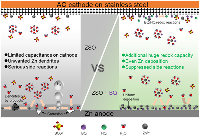
Figure 1.
Diagrams of the interfacial chemistry at the anode and cathode in ZSO and BQ-0.5 electrolytes.

The extensive employment of consumer electronics, electric vehicles, and grid-scale energy storage persistently demands the ceaseless evolution of high-performance energy storage devices [1]. Aqueous zinc-ion hybrid supercapacitors (AZICs) represent a distinct class of energy storage systems, constructed with carbon-based cathodes and Zn metal anodes. They combine the high power density of supercapacitors with the high energy density of metal-ion batteries [2-5]. Additionally, the metallic zinc anode offers advantages such as a high capacity, a low redox potential, and cost-effective manufacturing. These virtues render AZICs a novel energy storage system with highly promising application prospects. However, issues like hydrogen evolution reaction (HER), dendrite growth, and the formation of basic zinc salt by-products on the Zn anode result in a low Coulombic efficiency (CE), capacity deterioration, and short circuits in AZICs. The specific capacity of carbon-based cathodes is considerably lower than that of battery materials, leading to unsatisfactory energy density for AZICs [6-11]. Addressing the problems associated with both the cathode and anode of AZICs simultaneously remains extremely challenging.
Extensive research efforts have been devoted to stabilizing Zn anodes, encompassing artificial solid-electrolyte interphase (SEI) construction [12-14], three-dimensional host design, electrochemical etching-based alloying [15], and electrolyte engineering strategies (solvent molecular design [16,17], multifunctional additives [18]). Among these approaches, electrolyte engineering stands out as a scalable and cost-effective solution to suppress parasitic reactions while enabling uniform Zn2+ deposition. Current electrolyte engineering paradigms primarily include: Deep eutectic electrolytes [19], mixed electrolytes [20], high-concentration electrolytes [21], and electrolyte additives [22]. The additive strategy, in particular, offers distinct advantages such as ease of implementation, versatility in additive selection (spanning organic, inorganic, and polymeric compounds), and significant performance enhancement. These additives modulate electrode-electrolyte interfacial reactions through three key mechanisms: restructuring Zn2+ solvation shells, adsorbing on the anode to form protective double layers, and facilitating in situ SEI formation. As a result, water-related side reactions can be significantly suppressed, and the zinc deposition behavior can be homogenized [23]. Organic additives, by virtue of their plentiful functional groups and diverse molecular structures, can be screened or assembled into target molecules according to requirements. This offers a broad spectrum of options for stabilizing the zinc anode. For example, Yu et al. developed a trifunctional additive DTPA [24], which simultaneously forms a conformal shielding layer on Zn, tailors Zn2+ solvation structures, and buffers electrolyte pH fluctuations, thereby extending anode lifespan by 100-fold. However, to date, most additives primarily target the zinc anode and do not contribute to improving the energy density of the AZICs.
Hybridizing carbon-based cathodes with solid-state battery materials can enhance the energy density of AZICs, though this inevitably compromises their inherent advantages of high-power density. As an alternative, soluble redox-active organic molecules have been utilized as active electrolyte species in redox flow batteries, which can deliver high power capabilities due to rapid kinetics and diffusion of the organic molecules [25]. Thus, introducing redox-active additives with high activity and appropriate redox working potentials to AZICs may increase the capacity of the cathode without substantially sacrificing power density. A proposed strategy involves combining a cathode-targeted redox-active additive with an anode stabilizer to develop stable AZICs with high energy density [26,27]. However, potential cross-reactions or precipitation between the two additives may compromise their functionality, while additional additives also escalate battery cost and mass. Alternatively, designing a dual-function organic additive is reasonable and efficient to simultaneously increase the capacity and improve the stability of AZICs. Nevertheless, it is still challenging to screen such bi-functional additives since inappropriate active-redox additives for the cathode may exacerbate the side reactions of the zinc anode, thereby severely degrading cycling stability [28].
In this work, an organic active small molecule, p-benzoquinone (BQ), was used as a novel additive for AZICs. The BQ additive hinders the direct contact between water and the zinc metal by adsorbing on the surface of the zinc metal. Meanwhile, it replaces the H2O molecules coordinated with Zn2+ in the solvation sheath structure, reducing the reactivity of water, suppressing the formation of zinc dendrites, and reducing the formation of by-products (Fig. 1). In addition, the BQ undergoes reversible redox reactions to hydroquinone on the activated carbon (AC) cathode, significantly increasing the capacity of the cathode, from 40 mAh/g to 140 mAh/g at 0.5 A/g, alongside improved rate performance and doubled lifespan for AZICs.
In this work, 2 mol/L ZnSO4 (ZSO) was taken as the reference electrolyte. To determine the optimal concentration of the BQ additive, modified electrolytes with 0.05, 0.1, 0.2, 0.3, and 0.5 mol/L of BQ were prepared and labeled as BQ-0.05, BQ-0.1, BQ-0.2, BQ-0.3, and BQ-0.5, respectively (Fig. S1 in Supporting information). Excessive BQ additive, such as 0.6 mol/L, triggers aggregation, which is composed of BQ and ZnSO4·H2O crystals (Fig. S2 in Supporting information). Zn//Zn symmetric cells were fabricated to investigate the cycling stability of the zinc anode in different electrolytes. The BQ additive remarkably extends the lifespan under the conditions of 1 mA/cm2 and 1 mAh/cm2. Moreover, the longest lifespan is achieved with the BQ-0.5 electrolyte (Fig. S3 in Supporting information). Therefore, BQ-0.5 was the preferred electrolyte for all the subsequent experiments.
The interactions of BQ-0.5 molecules with the electrolyte were analyzed through theoretical calculations and experimental characterization. Molecular dynamics (MD) simulations were employed to simulate the structural evolution of the Zn2+ solvation sheath after adding the BQ-0.5 additive. Simulations revealed that BQ-0.5 molecules partially enter the primary solvation structure of hydrated Zn2+, displacing bound H2O molecules (Figs. 2a and b) [29]. Analysis of the radial distribution function (RDF) indicates that BQ molecules coordinate with Zn2+ ions via Zn2+-O (BQ) bonds with a bond length of 2 Å and an average coordination number (ACN) of 0.1 (Fig. 2c), while the ACN of Zn2+-H2O decreased from 5.36 to 5.30 (Fig. S4 in Supporting information). Complementary liquid-state nuclear magnetic resonance (NMR) analysis shows a downfield shift in the 1H signal from 4.710 ppm to 4.703 ppm (Fig. 2d), further confirming weakened Zn2+-H2O interactions [30]. The H2O-deficient solvation structure of Zn2+ is beneficial to decrease HER when plating Zn [31,32]. In addition, the Raman spectroscopy spectra of ZSO and BQ-0.5 electrolytes show that the symmetric stretching vibration peak of SO42- (υ(SO42-)) shifts from 979.94 cm-1 to a higher frequency of 981.05 cm-1 after adding BQ molecules (Fig. S5a in Supporting information), implying changes in the solvation structure of Zn2+ [19,33]. The υ(SO42-) peak can be further decomposed into solvent-separated ion pairs (SSIP, [Zn2+(H2O)6·SO42-]) and contact ion pairs (CIP, [Zn2+(H2O)5·OSO32-]) (Figs. S6a and b in Supporting information) [34]. The introduction of BQ-0.5 leads to an increase in the ratio of CIP, suggesting that the additive molecules weaken the electrostatic interaction between Zn2+ and H2O and facilitate the entry of SO42− into the primary solvation sheath [35]. Furthermore, the peaks corresponding to the υ(O—H) stretching vibration of H2O in the range of 2750–4000 cm-1 are resolved into three peaks, corresponding to strong, medium, and weak H—O bonds (Fig. S7a in Supporting information) [30,36]. With the BQ additive, the proportion of strong H—O bonds increases from 73.23% to 78.47%, whereas the proportion of weak H—O bonds decreases from 11.73% to 7.74% (Fig. S7b in Supporting information), revealing disrupted hydrogen bonds between H2O solvent molecules [37,38]. It reduces water molecules within Zn-ions solvation sheaths and the free water in the electrolyte, thus inhibiting water-related side reactions [37]. The impact of the BQ additive on the anode-electrolyte interface was then analyzed. Contact angle measurements demonstrate that BQ-0.5 electrolyte exhibits lower contact angles on zinc foil compared to the baseline ZSO electrolyte (Fig. S8 in Supporting information), confirming enhanced wettability at the anode surface.
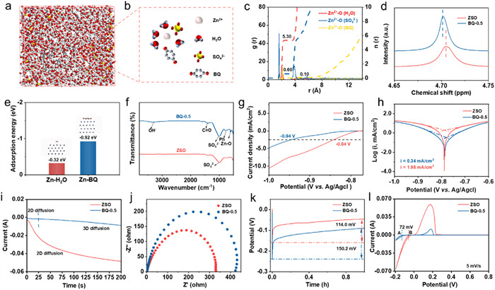
The results of density function theory (DFT) calculation further reveal the interactions between BQ molecules and the Zn anode. As shown in Fig. 2e, the adsorption energies of BQ and H2O on the (002) plane of Zn metal are −0.92 eV and −0.32 eV, respectively, indicating a higher affinity of BQ to the Zn anode for the BQ additive over H2O [39]. The enhanced wettability of the BQ-0.5 electrolyte reduces the interfacial free energy between metallic Zn and the electrolyte [40], thereby contributing to the uniform distribution of zinc ions at the interface and promoting uniform nucleation and deposition of Zn2+ [41,42].The X-ray photoelectron spectroscopy (XPS) of the Zn anode after 50 cycles (1 mA/cm2, 1 mAh/cm2) reveals the adsorption behavior of BQ molecules on the Zn anode. The O 1s XPS spectrum of the zinc electrode after cycling in the BQ-0.5 electrolyte can be deconvoluted into three peaks, namely Zn-O (at 528.84 eV), C = O (at 530.52 eV), and C—O (at 531.54 eV), as depicted in Fig. S4b. The C-related peaks confirm the adsorption of BQ on the Zn electrode [43,44]. The electrostatic potential calculated by DFT further manifests that BQ-0.5 is adsorbed on the surface of Zn metal through the negative-polarized carbonyl group (-C = O) [45], as shown in Fig. S9 (Supporting information). In addition, the DFT calculation results also show that the lowest unoccupied molecular orbital (LUMO) energy level (−5.55 eV) of the BQ molecule is lower than that of the H2O molecule (1.06 eV) (Fig. S10 in Supporting information). This indicates that the BQ additive is more likely to obtain electrons and form stronger chemisorption on the Zn electrode than H2O molecules. It can be validated by the reduced capacitance on the zinc anode in the BQ-0.5 electrolyte compared to that in ZSO (Fig. S5c in Supporting information) [46,47]. Furthermore, the FTIR spectrum of Zn anode after cycling in the BQ-0.5 electrolyte presents a C = O peak and two peaks attributed to the benzene ring (pH) at 1400 and 746 cm-1 (Fig. 2f), further proving the adsorption of BQ-0.5 on the Zn anode [48]. The preferential adsorption of BQ over H2O molecules forms an H2O-deficient inner Helmholtz plane (IHP) at the electrolyte-electrode interface, which is effective in suppressing H2O-related side reactions [49].
The influence of the BQ additive on the H2O-related side reactions and Zn deposition behaviors was then investigated. The linear scanning voltammetry (LSV) of the Zn anode at 2.5 mA/cm2 shows that the HER potential increases from −0.84 V to −0.94 V (vs. Ag/AgCl) and the oxygen evolution (OER) reaction potential is increased by 34 mV after introducing the BQ additive (Fig. 2g and Fig. S11 in Supporting information). Increased overpotentials for both HER and OER are inducive to suppressing the decomposition of H2O [50,51]. Tafel analysis further demonstrated a reduction in the Zn anode corrosion current density from 1.98 mA/cm2 (baseline ZSO) to 0.34 mA/cm2 with BQ-0.5 (Fig. 2h), confirming significantly mitigated Zn self-corrosion [52]. Effective inhibition of H2O decomposition and self-corrosion minimizes basic zinc salt byproduct formation [53], thereby alleviating passivation and enabling uniform Zn deposition [54]. Such improvements originate from the BQ-induced dehydration of Zn2+ solvation shells and the H2O-depleted inner Helmholtz plane (IHP) [49]. Chronoamperometric characterization highlighted distinct Zn deposition patterns with BQ-0.5 (Fig. 2i). In ZSO electrolyte, the current increases rapidly and continuously in 200 s, indicating the growing effective surface area for ion adsorption. This is attributed to the two-dimensional diffusion of Zn2+, resulting in non-uniform nucleation and disordered Zn deposition [55,56]. Conversely, BQ-0.5 electrolyte exhibits current stabilization after an initial 25 s nucleation process, signifying constant electrode area maintenance through homogeneous Zn deposition [57,58]. This transition from 2D to 3D diffusion-dominated deposition is attributed to BQ-0.5′s regulatory effect on Zn2+ migration pathways [59,60].
The electrochemical impedance spectroscopy (EIS) plots of symmetric Zn//Zn cells in Fig. 2j demonstrate that the charge transfer resistance (Rct) is increased after introducing the BQ-0.5 additive, which will decrease the nucleation radius of Zn grains [61,62] and thereby promote uniform Zn deposition [62]. The increased Rct can be attributed to that the adsorbed BQ on the zinc anode surface impedes the adsorption of Zn2+ on the Zn anode [61]. Polarized curves and cyclic voltammetry (CV) curves of Zn//Cu asymmetric cells display elevated nucleation overpotential (NOP) in the BQ-0.5 electrolyte by 36.2 and 72 mV, respectively (Figs. 2k and l). The elevated nucleation overpotential can promote the generation of more and smaller nuclei, which is crucial for uniform Zn plating [63,64]. The Zn2+ transference number was calculated through the I-t curve (polarization potential −10 mV) and EIS tests (Fig. S12 in Supporting information). The BQ additive significantly increases the Zn2+ transference number in the Zn//Zn cell from 0.205 to 0.85. It means a smaller Zn2+ concentration gradient and a more uniform electric field distribution, which can homogenize the Zn deposition [65,66]. The increased Zn2+ transference number can be attributed to the accelerated de-solvation of Zn2+ with an H2O-deficient primary solvation sheath and repulsed transfer of SO42- ions by the negative-polarized carbonyl groups on the Zn anode [67,68].
The regulatory effect of BQ-0.5 on the Zn deposition and stripping dynamics was directly visualized through in situ optical microscopy. As depicted in Fig. 3a, the Zn anode in ZSO electrolyte exhibits dendritic growth within 5 min of deposition at 10 mA/cm2, progressing to large-scale dendrites after 15 min. During subsequent stripping, incomplete dissolution left substantial "dead Zn" residues on the anode surface. Conversely, the BQ-0.5 electrolyte maintained a smooth Zn morphology throughout both deposition and stripping cycles (Fig. 3b). The comparison demonstrates the significant effect of the BQ additive in homogenizing the Zn deposition and stripping. Post-cycling characterization via X-ray diffraction (XRD) further validates this behavior. After 100 cycles at 1 mA/cm2 and 1 mAh/cm2, the Zn anode in ZSO electrolyte displays prominent diffraction peaks corresponding to zinc hydroxide sulfate hydrate (Zn4SO4(OH)6·0.5H2O) and zinc hydroxide hydrate (Zn(OH)2·0.5H2O) byproducts (Fig. 3c) [69], in sharp contrast to negligible by-products characteristic peaks in the BQ-0.5 electrolyte. Further energy dispersive X-ray spectroscopy (EDS) of the zinc anode surface shows (Fig. S13 in Supporting information) the existence of O and S elements with a proportion of 18.85% and 3.11%, respectively, in the ZSO electrolyte, much higher than 4.57% and 0.35% in the BQ-0.5 electrolyte (Table S1 in Supporting information). The reduced O and S elements, coming from H2O and SO42- ions, confirm the inhibitory effect of BQ-0.5 on the by-products [70]. Consistent with optical observations, microscopic morphology analysis reveals that the Zn electrode cycled in BQ-0.5 is smooth, while the surface of the Zn electrode in ZSO is covered by disorderly stacked dendrites and by-products (Figs. 3d and e). The cross-sectional SEM further shows that the Zn deposits in the BQ-0.5 electrolyte are relatively uniform and dense, in contrast with the loose and uneven deposition in the ZSO electrolyte (Figs. S14a and b in Supporting information). Even Zn deposition and suppressed passivation are attributed to uniform Zn nucleation and suppressed side reactions.
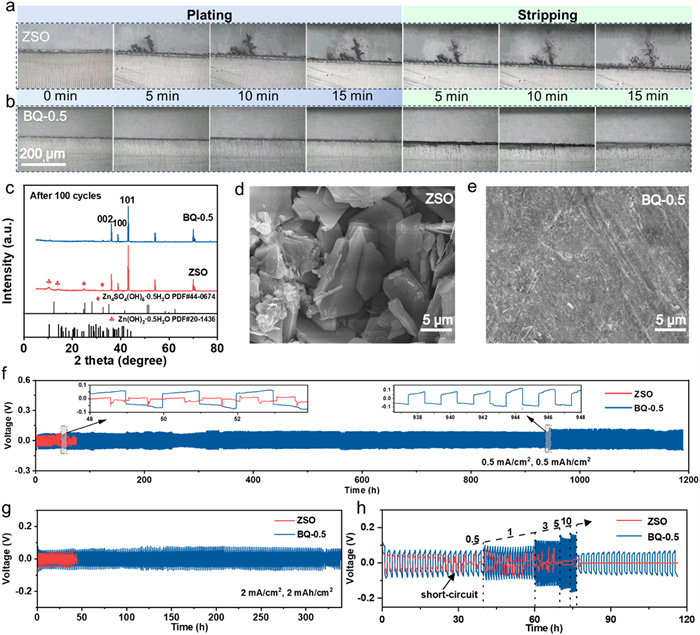
The stabilizing effect of the BQ-0.5 additive on the zinc anode was then characterized. As shown in Fig. 3f, the voltage of the Zn//Zn symmetric cell in the ZSO electrolyte suddenly drops after cycling for 34 h, suggesting an internal short circuit. In contrast, the symmetric cell cycles stably for 1188 h in the BQ-0.5 electrolyte, which is 35 times the cycling life of the ZSO electrolyte. The excellent protecting effect of BQ on the stability of Zn anodes surpasses recently reported electrolyte additives in Table S2 (Supporting information). The cell with the BQ additive exhibits a larger voltage hysteresis (Fig. S15 in Supporting information), which might be due to the increased energy barrier for Zn2+ migration by the adsorbed BQ molecules [71]. The increased potential hysteresis may reduce the nucleation size and promote uniform Zn deposition [72,73]. At 2 mA/cm2 and 2 mAh/cm2, the symmetric cell with the BQ-0.5 electrolyte still cycles for 338 h, significantly longer than that in the ZSO electrolyte (Fig. 3g). Furthermore, the Zn//Zn symmetric cell in the ZSO electrolyte undergoes a short-circuit during the rate test, whereas the cell in the BQ-0.5 electrolyte successfully completes the rate test and demonstrates stable plating/stripping overpotentials (Fig. 3h). The alternating cycling and static placement (24 h) test results in Fig. S16 (Supporting information) depict that the symmetric cell with BQ-0.5 can stably operate many times after standing. Remarkably, the symmetric cell without the additive demonstrates obvious voltage fluctuations and a short circuit in the first cycle. In addition, the Zn//Cu half-cell in the BQ-0.5 electrolyte maintains an average Coulombic efficiency (CE) of 99.30% during 1420 cycles at 1 mA/cm2 and 0.5 mAh/cm2, while the cell in the ZSO electrolyte short circuits after only 204 cycles (Figs. S17a and b in Supporting information). Collectively, the improved lifespan, stability of potential hysteresis, and Coulombic efficiency demonstrate the effective promotion of BQ-0.5 additive on the reversibility and stability of Zn electrode through dual mechanisms: parasitic reaction suppression and uniform Zn deposition.
Electrochemical performance tests were carried out in activated carbon//Zn AZICs (AC//Zn). As shown in Fig. 4a, the AZIC exhibits rectangular-like CV curves at different scanning rates in the ZSO electrolyte, consistent with the capacitive behavior of the activated carbon cathode. Surprisingly, a pair of prominent redox peaks emerge in the CV curves in the BQ-0.5 electrolyte (Fig. 4b), indicating redox reactions of the BQ additive on the AC cathode. The specific capacities of the cathode at different current densities are dramatically enhanced (Fig. S18 in Supporting information). The specific capacity increases 3.5-fold from 40 mAh/g to 140 mAh/g at 0.5 A/g, and 4-fold from 25 mAh/g to 100 mAh/g at 10 A/g (Fig. 4c). AC//AC symmetric supercapacitors with the ZSO and BQ-modified electrolytes demonstrate higher specific capacities with a higher concentration of BQ additive at different current densities (Fig. S19 in Supporting information). It confirms the reversible reactions of the BQ additive and contributes an additional capacity besides capacitance. The redox reactions are attributed to the rapid and reversible transition between BQ and hydroquinone (HQ) molecules on the AC electrode (Fig. S20 in Supporting information), according to previous studies [74,75]. The results also indicate that BQ-0.5 is the optimal electrolyte for enhancing the capacity of AZICs.
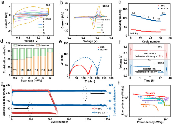
The contributions of the surface capacitance (k1v) and the diffusion-controlled reactions (k2v1/2) to the capacity of the AZICs in the BQ-0.5 electrolyte are quantified using the equation i(v) = k1v + k2v1/2, derived from CV data [74]. The ratios of the capacitive contributions reach 59.3%, 60.5%, 66.3%, 71.6%, 71.9%, and 86.5% at scan rates of 0.5, 1, 2, 3, 5, and 10 mV/s, respectively (Fig. 4d). This indicates that surface capacitance is dominant in energy storage in the BQ-0.5 electrolyte, which is advantageous for retaining a high energy and power density at large current densities due to the rapid interfacial kinetics [76]. In addition, the Rct of the AZICs increases in the BQ-0.5 electrolyte (Fig. 4e), which can be attributed to increased impedance on the Zn anode induced by the BQ adsorption [77,78]. The AZIC in BQ-0.5 electrolyte has a 93.8% capacity retention rate after standing for 48 h, much higher than the 72.7% in ZSO electrolyte (Fig. 4f). This can be attributed to the stabilized zinc anode in BQ-0.5 electrolyte [79]. Furthermore, the Coulombic efficiency (CE) suddenly drops at the 558th cycle and a short-circuit occurs at the 712th cycle at 1 A/g in the ZSO electrolyte. In contrast, the AZIC with the BQ-0.5 additive stably runs 1500 cycles and maintains a relatively high average CE of 97.7% (Fig. 4g). The cycling test results demonstrate the crucial role of BQ additives in improving the reversibility and stability of zinc plating/stripping. Besides, the AZIC in this work also exhibits exceptional energy and power densities, superior to other reported AZICs (Fig. 4h), including AC//Zn(CF3SO3)2//Zn [80], AC//ZnSO4//Zn [81], graphite//Zn(CH3COO)2//Zn [82], FCNSs//Zn(CF3SO3)2//Zn [83], ACC//Zn(TFSI)2//Zn [84], MnO2//ZnSO4//Zn [85], and MXene-rGO2//ZnSO4//Zn [86]. The comparison displays the great advantages of the dual-function BQ additive in improving the power density and energy density of the AZICs. In addition, BQ is an inexpensive chemical intermediate, which is advantageous for its practical applications, but its biotoxicity must be properly managed.
In summary, the introduction of p-benzoquinone (BQ) as a bifunctional organic additive into ZnSO4 electrolyte not only enhances the electrochemical stability and reversibility of the zinc anode but also improves the capacity, power density, and energy density of the device. Mechanistically, BQ molecules adsorb on the zinc surface, restructure Zn2+ solvation shells, suppress H2O-induced parasitic reactions, and guide uniform Zn deposition. Consequently, the lifespan of the zinc anode is significantly extended from 35 h to 1188 h at 0.5 mA/cm2 and 0.5 mAh/cm2, with a high average CE of 99.30%. Additionally, the BQ additive provides an additional capacity to AC cathode through its rapid redox reactions, boosting specific capacity from 40 mAh/g to 140 mAh/g at 0.5 A/g while enhancing rate capability. As a result, the AZICs demonstrate a significantly enhanced lifespan alongside superior energy and power densities surpassing state-of-the-art AZICs. This study establishes a molecular engineering paradigm for high-performance AZICs through multifunctional redox-active additives, bridging anode stabilization with cathode capacity augmentation.
The authors declare that they have no known competing financial interests or personal relationships that could have appeared to influence the work reported in this paper.
Kai Guo: Writing – review & editing, Writing – original draft, Validation, Methodology, Investigation. Jiating Li: Methodology, Data curation. Shiya Lin: Supervision, Methodology. Lu Chen: Supervision. Neng Yu: Writing – review & editing, Supervision, Funding acquisition. Yiju Li: Writing – review & editing, Funding acquisition.
This work is supported by the National Natural Science Foundation of China (Nos. 52102214, 52302261, and 22479070), the Jiangxi Provincial Natural Science Foundation (Nos. 20242BAB25162, 20224BAB203016), and the National (Jiangxi Province) College Students Innovation and Entrepreneurship Training Program (Nos. S202410405034, S202410405043), the Guangdong Basic and Applied Basic Research Foundation (Nos. 2023B1515120069 and 2024A1515012705), Shenzhen Science and Technology Program (Nos. SGDX20230116091644003 and JCYJ20240813094903005), High Level of Special Funds (No. G03034K001), and Key Laboratory of Advanced Energy Materials Chemistry (Ministry of Education). The authors appreciate the material characterization service provided by Shiyanjia Lab (
Supplementary material associated with this article can be found, in the online version, at doi:
R. Liu, G. He, X. Wang, et al., Nat. Commun. 15 (2024) 280. doi: 10.1038/s41467-023-43884-x
W. Zuo, R. Li, C. Zhou, et al., Adv. Sci. 4 (2017) 1600539. doi: 10.1002/advs.201600539
H.D. Yoo, S.D. Han, R.D. Bayliss, et al., ACS Appl. Mater. Interfaces 8 (2016) 30853–30862. doi: 10.1021/acsami.6b08367
J. Lu, J. Zhang, X. Wang, et al., J. Energy Storage 103 (2024) 114338. doi: 10.1016/j.est.2024.114338
X. Qiu, N. Wang, Z. Wang, F. Wang, Y. Wang, Angew. Chem. Int. Ed. 60 (2021) 9610–9617. doi: 10.1002/anie.202014766
H. Xu, H. Liu, W. Yang, et al., Chem. Eng. J. 485 (2024) 149825. doi: 10.1016/j.cej.2024.149825
H. Zhai, H. Liu, Y. Zhang, et al., J. Mater. Sci. Technol. 188 (2024) 183–190. doi: 10.1016/j.jmst.2023.12.015
H. Xu, W. Yang, M. Li, et al., Small 20 (2024) e2310972. doi: 10.1002/smll.202310972
Z. Jiang, J. Wen, H. Xu, et al., Chem. Eng. Sci. 303 (2025) 120961. doi: 10.1016/j.ces.2024.120961
J. Liu, P. Xu, J. Liang, et al., Chem. Eng. J. 389 (2020) 124405. doi: 10.1016/j.cej.2020.124405
H. Xu, P. Guo, C. Li, et al., Adv. Funct. Mater. 35 (2025) 2415016. doi: 10.1002/adfm.202415016
K. Hu, X. Guan, R. Lv, et al., Chem. Eng. J. 396 (2020) 125363. doi: 10.1016/j.cej.2020.125363
Z. Li, Z. Gong, X. Wu, et al., Chin. Chem. Lett. 33 (2022) 3936–3940. doi: 10.1016/j.cclet.2021.11.015
X. Yan, X. Huang, Y. Liu, et al., Chin. Chem. Lett. 35 (2024) 109426. doi: 10.1016/j.cclet.2023.109426
X. Fu, G. Li, X. Wang, et al., J. Energy Chem. 88 (2024) 125–143. doi: 10.1016/j.jechem.2023.08.052
N. Zhao, Y. Liang, W. Huo, et al., Chin. Chem. Lett. 35 (2024) 109332. doi: 10.1016/j.cclet.2023.109332
J. Zhou, Q. Li, X. Hu, et al., Chin. Chem. Lett. 35 (2024) 109143. doi: 10.1016/j.cclet.2023.109143
S. Lin, W. Zhao, Y. Guo, et al., ACS Energy Lett. 9 (2024) 4614–4623. doi: 10.1021/acsenergylett.4c01646
F. Liu, Y. Zhang, G. Li, et al., Chem. Eng. J. 493 (2024) 152526. doi: 10.1016/j.cej.2024.152526
Y. Guo, R. Chua, Y. Chen, et al., Small 19 (2023) 2207133. doi: 10.1002/smll.202207133
A. Clarisza, H.K. Bezabh, S.K. Jiang, et al., ACS Appl. Mater. Interfaces 14 (2022) 36644–36655. doi: 10.1021/acsami.2c09040
H. Wang, H. Li, Y. Tang, et al., Adv. Funct. Mater. 32 (2022) 2207898. doi: 10.1002/adfm.202207898
H. Liu, P. Cao, Y. Chen, et al., J. Energy Chem. 99 (2024) 139–148. doi: 10.1016/j.jechem.2024.07.046
S. Lin, W. Zhao, Y. Guo, et al., ACS Energy Lett. 9 (2024) 4614–4623. doi: 10.1021/acsenergylett.4c01646
M. Park, E.S. Beh, E.M. Fell, et al., Adv. Energy Mater. 9 (2019) 1900694. doi: 10.1002/aenm.201900694
B. Hu, J. Luo, M. Hu, B. Yuan, T.L. Liu, Angew. Chem. Int. Ed. 58 (2019) 16629–16636. doi: 10.1002/anie.201907934
Z. Li, Y.C. Lu, Chem 4 (2018) 2020–2021. doi: 10.1016/j.chempr.2018.08.032
H. Xu, W. Yang, H. Liu, et al., Chem. Eng. J. 465 (2023) 142896. doi: 10.1016/j.cej.2023.142896
Y. Yang, Y. Li, Q. Zhu, B. Xu, Adv. Funct. Mater. 34 (2024) 2316371. doi: 10.1002/adfm.202316371
P. Sun, L. Ma, W. Zhou, et al., Angew. Chem. Int. Ed. 60 (2021) 18247–18255. doi: 10.1002/anie.202105756
Y. Li, H. Xu, X. Xuan, et al., Chem. Eng. J. 505 (2025) 158934. doi: 10.1016/j.cej.2024.158934
D. Xu, X. Ren, H. Li, et al., Angew. Chem. Int. Ed. 63 (2024) e202402833. doi: 10.1002/anie.202402833
J. Yin, M. Li, X. Feng, et al., J. Alloys Compd. 971 (2024) 172785. doi: 10.1016/j.jallcom.2023.172785
J. Chen, N. Liu, W. Dong, et al., Adv. Funct. Mater. 34 (2024) 2313925. doi: 10.1002/adfm.202313925
H. Liu, Z. Xin, B. Cao, et al., J. Mater. Chem. A 12 (2024) 20229–20237. doi: 10.1039/d4ta03031a
Y. Liang, M. Qiu, P. Sun, W. Mai, Chem. Sci. 15 (2024) 1488–1497. doi: 10.1039/d3sc05334b
Q. Zhang, K. Xia, Y. Ma, et al., ACS Energy Lett. 6 (2021) 2704–2712. doi: 10.1021/acsenergylett.1c01054
Q. Meng, R. Zhao, P. Cao, et al., Chem. Eng. J. 447 (2022) 137471. doi: 10.1016/j.cej.2022.137471
H. Liang, J. Wu, J. Wang, Z. Yang, J. Colloid Interface Sci. 661 (2024) 730–739. doi: 10.1016/j.jcis.2024.01.211
Q. Gou, H. Luo, Y. Zheng, et al., Small 18 (2022) 2201732. doi: 10.1002/smll.202201732
L. Wang, Z. Wang, H. Li, et al., ACS Nano 17 (2023) 668–677. doi: 10.1021/acsnano.2c09977
C. Xie, Q. Zhang, Z. Yang, et al., Chin. Chem. Lett. 33 (2022) 2653–2657. doi: 10.1016/j.cclet.2021.09.083
H. Liu, P. Cao, Y. Chen, et al., J. Energy Chem. 99 (2024) 139–148. doi: 10.1016/j.jechem.2024.07.046
K. Zhao, F. Liu, G. Fan, et al., ACS Appl. Mater. Interfaces 13 (2021) 47650–47658. doi: 10.1021/acsami.1c14407
T. Yan, M. Tao, J. Liang, et al., Energy Storage Mater. 65 (2024) 103190. doi: 10.1016/j.ensm.2024.103190
K. Qi, P. Liang, S. Wei, et al., Energy Environ. Sci. 17 (2024) 2566–2575. doi: 10.1039/d4ee00147h
M. Han, J. Zhang, C. Yu, et al., Angew. Chem. Int. Ed. 63 (2024) e202403695. doi: 10.1002/anie.202403695
J.Y. Kim, G. Liu, G.Y. Shim, H. Kim, J.K. Lee, Adv. Funct. Mater. 30 (2020) 2004210. doi: 10.1002/adfm.202004210
J. Chen, Y. Xu, Y. Wang, et al., Energy Storage Mater. 72 (2024) 103765. doi: 10.1016/j.ensm.2024.103765
T. Yan, M. Tao, J. Liang, et al., Energy Storage Mater. 65 (2024) 103190. doi: 10.1016/j.ensm.2024.103190
Z. Zhao, J. Zhao, Z. Hu, et al., Energy Environ. Sci. 12 (2019) 1938–1949. doi: 10.1039/c9ee00596j
H. Yu, Y. Chen, W. Wei, X. Ji, L. Chen, ACS Nano 16 (2022) 9736–9747. doi: 10.1021/acsnano.2c03398
K. Zhao, J. Zhao, M. Yu, et al., Chem. Res. Chin. Univ. 40 (2024) 722–729. doi: 10.1007/s40242-024-4110-9
Z. Chen, R. Jiang, Y. Chen, et al., Energy Storage Mater. 74 (2025) 103913. doi: 10.1016/j.ensm.2024.103913
C. Huang, F. Huang, X. Zhao, et al., Adv. Funct. Mater. 33 (2023) 2210197. doi: 10.1002/adfm.202210197
Y. Lyu, J.A. Yuwono, P. Wang, et al., Angew. Chem. Int. Ed. 62 (2023) e202303011. doi: 10.1002/anie.202303011
T. Yan, M. Tao, J. Liang, et al., Energy Storage Mater. 65 (2024) 103190. doi: 10.1016/j.ensm.2024.103190
C. Huang, F. Huang, X. Zhao, et al., Adv. Funct. Mater. 33 (2023) 2210197. doi: 10.1002/adfm.202210197
H. Yu, D. Chen, Q. Li, et al., Adv. Energy Mater. 13 (2023) 2300550. doi: 10.1002/aenm.202300550
F. Wang, J. Zhang, H. Lu, et al., Nat. Commun. 14 (2023) 4211. doi: 10.1038/s41467-023-39877-5
T. Yan, M. Tao, J. Liang, et al., Energy Storage Mater. 65 (2024) 103190. doi: 10.1016/j.ensm.2024.103190
H. Peng, D. Wang, X. Wang, et al., Adv. Funct. Mater. 35 (2025) 2417695. doi: 10.1002/adfm.202417695
M. Wu, Y. Sun, Z. Yang, et al., Angew. Chem. Int. Ed. (2024) e202407439.
Q. Meng, R. Zhao, P. Cao, et al., Chem. Eng. J. 447 (2022) 137471. doi: 10.1016/j.cej.2022.137471
H. Yan, S. Li, Y. Nan, S. Yang, B. Li, Adv. Energy Mater. 11 (2021) 2100186. doi: 10.1002/aenm.202100186
C. Lin, X. Yang, P. Xiong, et al., Adv. Sci. 9 (2022) 2201433. doi: 10.1002/advs.202201433
W. Song, J. Liu, S. Rao, et al., Adv. Sci. 11 (2024) 2400094. doi: 10.1002/advs.202400094
S. Cai, J. Hu, Y. Luo, et al., Chem. Eng. J. 454 (2023) 140145. doi: 10.1016/j.cej.2022.140145
H. Wang, W. Ye, B. Yin, et al., Angew. Chem. Int. Ed. 62 (2023) e202218872. doi: 10.1002/anie.202218872
M. Wu, Y. Sun, Z. Yang, et al., Angew. Chem. Int. Ed. (2024) e202407439.
R.A. House, U. Maitra, M.A. Pérez-Osorio, et al., Nature 577 (2020) 502–508. doi: 10.1038/s41586-019-1854-3
N. Zhang, F. Cheng, Y. Liu, et al., J. Am. Chem. Soc. 138 (2016) 12894–12901. doi: 10.1021/jacs.6b05958
H. Peng, X. Wang, F. Yang, et al., Chem. Eng. J. 474 (2023) 145864. doi: 10.1016/j.cej.2023.145864
X. Gan, C. Zhang, X. Ye, L. Qie, K. Shi, Energy Storage Mater. 65 (2024) 103175. doi: 10.1016/j.ensm.2024.103175
W. Fang, H. Luo, I.M. Mwakitawa, et al., ChemSusChem 18 (2024) e202401749.
Y. Lu, J. Colloid Interface Sci. 651 (2023) 296–303. doi: 10.1016/j.jcis.2023.07.208
Z. Wang, J. Diao, G. Henkelman, C.B. Mullins, Adv. Funct. Mater. 34 (2024) 2314002. doi: 10.1002/adfm.202314002
S. Cai, J. Hu, Y. Luo, et al., Adv. Funct. Mater. 34 (2024) 2309667. doi: 10.1002/adfm.202309667
Y. Liu, K. Dong, T. Lv, et al., Small Struct. 4 (2023) 2300046. doi: 10.1002/sstr.202300046
H. Wang, M. Wang, Y. Tang, Energy Storage Mater. 13 (2018) 1–7.
L. Dong, X. Ma, Y. Li, et al., Energy Storage Mater. 13 (2018) 96–102. doi: 10.1016/j.ensm.2018.01.003
Z. Liu, G. Li, T. Cui, et al., J. Solid State Electrochem. 22 (2018) 91–101. doi: 10.1007/s10008-017-3725-x
H. Zhou, C. Liu, J.C. Wu, et al., J. Mater. Chem. A 7 (2019) 9708–9715. doi: 10.1039/c9ta01256g
Y. Liang, M. Qiu, P. Sun, W. Mai, Adv. Funct. Mater. 33 (2023) 2304878. doi: 10.1002/adfm.202304878
X. Ma, J. Cheng, L. Dong, et al., Energy Storage Mater. 20 (2019) 335–342. doi: 10.1016/j.ensm.2018.10.020
Q. Wang, S. Wang, X. Guo, et al., Adv. Electron. Mater. 5 (2019) 1900537. doi: 10.1002/aelm.201900537

Figure 1 Diagrams of the interfacial chemistry at the anode and cathode in ZSO and BQ-0.5 electrolytes.

Figure 2 Characterization of the influence of the BQ additive on the electrolyte chemical structure and interface of Zn anode. (a) The MD simulation snapshot of the BQ-0.5 electrolyte and (b) local solvation structure of hydrated Zn2+. (c) RDFs for Zn2+-O computed from MD simulations of the BQ-0.5 electrolyte. (d) 1H NMR spectra of ZSO and BQ-0.5 electrolytes. (e) Adsorption modes of H2O and BQ on Zn (002) surface and corresponding adsorption energy. (f) FTIR spectra of Zn anode surface after cycling in BQ-0.5 and ZSO electrolytes. (g) LSV curves at 1 mV/s. (h) Tafel curve in the polarized voltage window ranging from −1.0 mV to −0.6 mV. (i) Chronoamperometry curves of Zn electrode at an overpotential of −150 mV. (j) EIS spectra of the Zn symmetric cells with/without the BQ-0.5 additive. (k) Polarized curves of Zn//Cu asymmetric cells at 1 mA/cm2. (l) CV curves of Zn//Cu asymmetric cells at 5 mV/s.

Figure 3 Characterization of Zn deposition and electrochemical performance in the ZSO and BQ-0.5 electrolytes. In situ optical visualization observations of Zn deposition/stripping at 10 mA/cm2 in the (a) ZSO and (b) BQ-0.5 electrolyte. (c) XRD patterns. SEM images of Zn electrodes after cycling at 1 mA/cm2, 1 mAh/cm2 for 100 cycles in the (d) ZSO and (e) BQ-0.5 electrolyte. Long-term stripping/plating profiles of Zn//Zn symmetric cells (f) at 0.5 mA/cm2, 0.5 mAh/cm2, and (g) at 2 mA/cm2, 2 mAh/cm2. (h) Rate performance of Zn//Zn symmetric cells at current densities of 0.5, 1, 3, 5, 10 mA/cm2 with a capacity of 1 mAh/cm2.

Figure 4 Electrochemical performance characterization of AZICs in the ZSO and BQ-0.5 electrolytes. CV profiles at various scanning rates (a) with and (b) without the BQ additive. (c) Rate capability of AC//Zn AZICs in ZSO and BQ-0.5 electrolytes. (d) Calculated contribution ratios versus scanning rates in the BQ-0.5 electrolyte. (e) EIS plots, (f) self-discharge curves, and (g) cycling performance of AZICs at 1 A/g. (h) Ragone plots of AZICs based on BQ-0.5 electrolyte and recently reported AZICs.

 扫一扫看文章

扫一扫关注我们
 DownLoad:
 下载:
下载:
 下载:
下载: