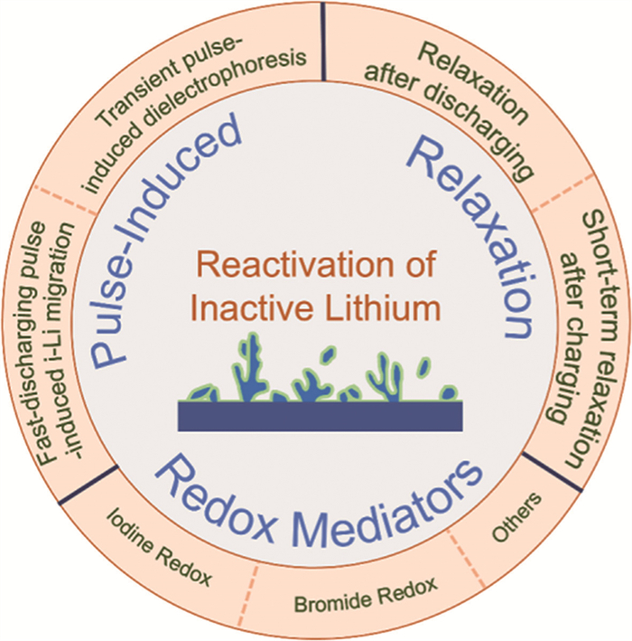
Figure 1.
Emerging strategies for the recovery of inactive lithium.

Reactivation of inactive lithium in rechargeable lithium batteries: From fundamental research to industrial applications
Pu Guo , Dandan Yu , Yuzhen Zhao , Hua Wang


Lithium-ion batteries (LIBs) have been widely adopted due to their high energy density and long lifespan, which significantly transform modern life [1,2]. In 2019, the Nobel Prize in Chemistry was awarded to Prof. John B. Goodenough, M. Stanley Whittingham, and Akira Yoshino for their outstanding contributions to the field of LIBs. With the development of human society and the advancement of science and technology, LIBs are facing new and more stringent performance requirements, such as higher energy density [3-5], shorter charging time [6], longer cycle life [7-9], enhanced safety, and wider operating temperature range [10-14]. During charging, when the potential of the anode approaches or falls below the deposition potential of lithium metal, lithium ions (Li+) are reduced and deposited on the anode surface in the form of metallic lithium [15-21]. During discharge, the anode undergoes the stripping of metallic lithium and the deintercalation of Li+ [22-24]. In fact, it is impossible to achieve complete stripping of metallic lithium, and the formation of electrically isolated lithium (i-Li) cannot be avoided during repeated cycling [25,26]. Furthermore, the solid electrolyte interphase (SEI) layer can be built on the anode surface owing to the electrolyte reductive decomposition at low potentials. Isolated lithium, along with lithium-containing species contained in the SEI, is collectively referred to as "dead lithium" or "inactive lithium" [27,28]. The continuous accumulation of inactive lithium during cycling is the main cause of irreversible capacity loss and shortened cycle life of LIBs [26,29-31].
At present, a variety of anode materials are employed in LIBs, such as lithium metal [32-34], graphite [32,35], and silicon-based composites [36-38]. The formation of inactive lithium during repeated charge-discharge processes remains a common and persistent challenge. Various strategies including regulating electrolyte composition [39-41], introducing lithium supplements [42,43], modifying current collectors [44-47], and constructing artificial SEI, have been developed to address this issue [48,49]. Nevertheless, these strategies primarily focus on suppressing or decreasing the formation of inactive lithium. In contrast, the reactivation of existing inactive lithium to mitigate capacity loss and enhance cycle life of LIBs has emerged as an increasingly important and promising research direction. From an industrial perspective, several critical factors must be considered for practical applications, such as scalability, cost-effectiveness, safety, and compatibility with existing battery technologies. With the in-depth research on LIBs, emerging insights into the reactivation of inactive lithium and relevant mechanisms have inspired a series of studies focused on its revival and reintegration into the electrochemical system.
In general, by implementing current/voltage pulses and electric field relaxation, inactive lithium can be re-connected electrically and regained its activity under the potential gradient of the electrolyte or dielectrophoresis. These approaches hold great promise for direct integration into existing battery systems and can be implemented during the battery operation and maintenance, enabling the capacity recovery of LIBs and providing valuable insights for optimizing charging-discharging protocols. Furthermore, the introduction of redox mediators, such as I3−/I−, Br3−/Br−, 2,2,6,6-tetramethylpiperidine oxide (TEMPO), enables spontaneous reactions with inactive lithium, thereby compensating for lithium loss and achieving high Coulombic efficiency (CE) and capacity retention. However, the use of these redox mediators is prone to cause battery self-discharge. In addition, considering the complexity of cell fabrication and the associated costs, it remains challenging to integrate these strategies into current commercial battery systems.
Herein, this review mainly focuses on the research of inactive lithium in lithium metal batteries (LMBs), graphite-based LIBs, and silicon-based LIBs. The influences of electrolyte composition, operating temperatures, stack pressures, voltages, and current densities on the formation of inactive lithium are thoroughly discussed. Moreover, current strategies for reviving inactive lithium are summarized (Fig. 1). Furthermore, the application prospects of these approaches are analyzed from the perspective of industrial applications. In addition, a promising strategy is proposed to recover inactive lithium by developing an intelligent charging protocol in combination with deep learning.
LIBs suffer from progressive capacity degradation during cycling, primarily due to the side reactions that occur during repeated charge-discharge processes. These factors include electrolyte decomposition, the formation and rupture of the SEI, and structural degradation or dissolution of the electrode active materials [50-53]. A particularly detrimental consequence of these degradation pathways is the formation of inactive lithium, which typically originates from the deposition of metallic lithium on the anode surface followed by its incomplete stripping. Such processes lead to electronically isolated lithium, often referred to as dead lithium, which no longer participates in subsequent electrochemical reactions. Among the various failure mechanisms, the accumulation of inactive lithium has emerged as a critical factor that significantly accelerates capacity fade and limits the cycle life of LIBs [16,27,54-56].
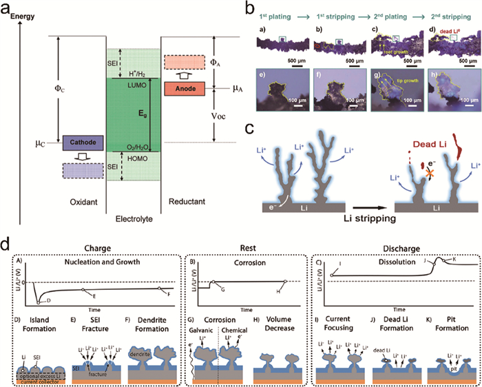
A fundamental origin of these side reactions mainly lies in the electrochemical stability window (ESW) of the electrolyte. When the anode potential drops below the energy level of the lowest unoccupied molecular orbital (LUMO) of the electrolyte, electrons from the anode can transfer into the electrolyte, which can initiate reduction reactions of the electrolyte and lead to SEI formation on the anode surface. The SEI acts as a semi-permeable barrier that mitigates further direct contact between the anode and electrolyte. When the cathode potential exceeds the energy level of the highest occupied molecular orbital (HOMO) of the electrolyte, electron transfer occurs from the electrolyte to the cathode, inducing oxidative decomposition reactions of the electrolyte and the formation of the cathode-electrolyte interphase (CEI), which establishes a new interfacial equilibrium state (Fig. 2a) [57-59].
The commercial breakthrough of LIBs occurred in 1991 when Sony introduced petroleum coke as a carbon anode material. Since then, graphite anodes have dominated the market, accounting for ~98% of LIB production. In LIBs, the Li+ shuttles between the cathode and anode during repeated cycling. When the Li+ flux exceeds the intercalation capacity of graphite, Li plating occurs on the anode surface [22]. The uneven metallic Li deposition repeatedly damages the SEI and promotes dendrite growth. The incomplete Li stripping further exacerbates the formation of electrically isolated lithium, which leads to more capacity loss [15].
The SEI layer has a heterogeneous structure composed of organic species, such as alkoxy lithium (ROLi) and lithium alkyl carbonates (e.g., RCOCO2Li and (CH2OCO2Li)2), and inorganic compounds (Li2O, LiOH, Li2CO3, LiF, Li3N, etc.) [50,60,61]. The SEI film formed on the anode surface exhibits pronounced microscopic heterogeneity, which leads to non-uniform current density distribution and uneven Li plating across the electrode surface. Such inhomogeneous Li deposition alters the surface curvature of the SEI, which further amplifies its microstructural heterogeneity and induces variations in interfacial resistance and local current densities. During this process, Li+ tends to nucleate preferentially at structural defects or high-curvature regions of the SEI film, generating localized electrochemically active sites. These sites facilitate further Li nucleation and dendritic growth as cycling continues. It has been demonstrated that insufficient mechanical strength of the SEI, which is often associated with a high proportion of organic components, along with the poor ionic conductivity resulting from the absence of inorganic compounds (such as LiF and Li3N), are critical factors contributing to these detrimental phenomena [62,63].
LMBs have garnered significant interest due to the ultrahigh theoretical specific capacity (3860 mAh/g) and low redox potential (–3.04 V vs. standard hydrogen electrode, SHE) of lithium metal anode, which offer a pathway beyond the energy-density limitation of commercial LIBs [64]. However, the high reactivity of lithium metal anode leads to parasitic side reactions with the electrolyte, forming an unstable SEI. This fragile SEI is prone to mechanical failure during cycling, which can expose fresh lithium and initiate further electrolyte degradation. The cumulative influence induces inhomogeneous Li deposition, which promotes the dendrite growth. What is worse, the irreversible Li stripping exacerbates this issue, leading to the formation of dead lithium during the prolonged cycling [17]. During repeated Li plating/stripping cycles, the fragile SEI undergoes continual fracture/repairment. The newly exposed anode surface subsequently participates in (electro-)chemical reactions with the electrolyte, which further exacerbates localized Li deposition and dendrite formation. This process not only accelerates the consumption of active lithium and electrolyte, but also causes irreversible changes in interfacial chemistry. Additionally, the Li stripping process imposes further mechanical stress on the SEI due to volume contraction. Owing to the uneven thickness and electrodissolution rate, Li tends to strip preferentially at the waist and root regions of dendrites, and often causes electrically isolated lithium (or dead lithium), which no longer participates in electrochemical reactions [65,66]. The accumulation of inactive lithium happens during prolonged cycling [29,63].
Electrolyte decomposition can also generate gaseous byproducts (e.g., H2, C2H4, CO2), which disturb the uniformity of Li deposition and promote the accumulation of electrochemically inactive lithium [67]. Xiang et al. [28] utilized a combination of mass spectrometry titration (MST) and 13C and 2H isotopic labeling techniques to demonstrate that the decomposition of ethylene carbonate continuously releases ethylene gas, which further reacts with lithium metal to form the electrochemically inactive species—LiH and Li2C2. Phase-field simulations further reveal that the presence of gas bubbles distorts the interfacial electric field distribution and ion concentration gradients, which exacerbates non-uniform Li deposition and the formation of dead lithium. Through rational electrolyte design, the formation of LiH and Li2C2 can be effectively mitigated by suppressing ethylene generation. This result was experimentally validated in graphite anode, which offers a promising approach to mitigate irreversible lithium loss.
Chen et al. [26] utilized Li foil and a copper wire as the counter electrode and working electrode, respectively, and employed in-situ optical microscopy to monitor the formation of inactive lithium during the Li deposition/stripping processes. During the second deposition, lithium metal grew from the root region closer to the copper wire, and the inactive lithium remaining on the copper wire after the first stripping process was pushed up by the newly deposited metallic Li (Fig. 2b). This study disclosed that Li0 is the primary component of the inactive lithium, while Li2O and Li2CO3 are the main components of the SEI. If part of the metallic Li cannot be converted into Li+ during the stripping process and becomes encapsulated by the insulating SEI, it will transform into inactive lithium in the subsequent cycling (Fig. 2c) [29].
In addition, Sanchez et al. [63] presented a simplified depiction of the morphological evolution of the anode during the cycling process, accompanied by the corresponding anode voltage profiles. Each cycling includes three primary stages (Fig. 2d): Charging (electrodeposition), rest (relaxation), and discharging (electrodissolution/stripping). During the charging process, the Li nucleation and the SEI formation occur simultaneously, which can take place on the surface of anode and newly deposited lithium. In the initial nucleation stage, the anode potential drops below the thermodynamic potential for Li deposition (0 V vs. Li/Li+) until the voltage reaches a peak. As charging continues, the voltage gradually rises to a plateau region due to the increasing surface area of the lithium deposition layer. In liquid electrolytes, this process often involves the formation of various non-planar morphologies, with the SEI on the deposited lithium surface undergoing continuous mechanical fracture, exposing fresh lithium metal surface to the electrolyte. During the rest period at the end of charging, the battery is maintained in an open-circuit state. The duration of this rest period significantly impacts battery performance. If the rest time is appropriate, the SEI film undergoes repair, and the Li metal surface regains stability, which can reduce the Li dendrite growth. However, an excessively long rest period may lead to uneven Li deposition within the battery, thereby influencing its cycling stability. In the subsequent discharge stage, the stripping of lithium metal results in the formation of dead lithium and surface pitting. The specific voltage behavior during stripping varies significantly depending on the morphology of the existing lithium deposition layer (the presence or absence of excess lithium) [63].
The generation and recovery of inactive lithium constitute a complex process influenced by multiple factors, including the electrolyte system, current density/voltage, internal battery temperature, and internal stress.
Liquid electrolytes commonly employed in LMBs predominantly include carbonate-based electrolytes and ether-based electrolytes [68-70]. Cyclic carbonate solvents (e.g., ethylene carbonate (EC), propylene carbonate (PC)) exhibit superior antioxidant stability compared to ether-based solvents. However, these cyclic carbonates can be reduced into alkyl lithium carbonates by the metallic lithium. During subsequent charging and discharging cycles, these alkyl lithium carbonates undergo further decomposing, which leads to structural changes in the SEI layer with a complex and multilayered structure due to the increasing porosity of the SEI. The inner layer of the SEI, adjacent to the anode surface, is predominantly composed of inorganic compounds such as LiF, Li2CO3, and Li2O. In contrast, the outer layer of the SEI consists of reduction products derived from the electrolyte solvents near the electrolyte interface, including alkyl lithium carbonates and oligomeric ethylene oxides [50,71-74]. The incorporation of linear carbonates (e.g., dimethyl carbonate (DMC), diethyl carbonate (DEC), and ethyl methyl carbonate (EMC)) into carbonate-based electrolytes can reduce the melting point and viscosity of the electrolyte. The reduction process during SEI formation is analogous to that observed when using fluorine-free cyclic carbonates alone. The resulting SEI exhibits poor stability and is prone to cracking, which accelerates the growth of mossy and dendritic lithium dendrites [71,75]. The incorporation of fluorinated carbonates as cosolvents or additives into the electrolyte system can enhance the uniformity of Li deposition, improve the stability of the SEI, and mitigate the growth of lithium dendrites [71,72,76].
The most widely used ether-based solvents in LMBs include dimethoxyethane (DME) and 1,3-dioxolane (DOL) [77-80]. In ether-based electrolytes, the inner SEI layer formed on Li metal anode predominantly consists of LiF and Li2O [81], while the outer layer contains elastomeric polyethers, enabling the high flexibility of the SEI. This structure significantly reduces SEI cracking, promotes more uniform lithium deposition, and facilitates the formation of spherical Li deposition, thereby remarkably decreasing Li dendrite growth and the accumulation of dead lithium. Consequently, the cycling lifespan and CE of the lithium metal anode are significantly enhanced. Nevertheless, the inherent instability of conventional ether-based solvents under high-voltage conditions (e.g., >4.2 V) severely restricts their application in high-energy full cells coupled with high-voltage cathodes [72,76,82-84].
To meet demand for wide-temperature and fast charging performance, carboxylate-based electrolytes have garnered substantial interest owing to their improved thermal stability and compatibility with high-rate electrochemical processes [12,82,85,86]. Carboxylate-based electrolytes exhibit lower melting points, viscosities, and desolvation energy barriers. However, they exhibit poor film-forming capabilities, readily react with the deposited lithium on the anode, and struggle to form a stable SEI. In some cases, they may even promote the formation of inactive lithium. With ongoing research and development of carboxylate-based electrolytes, the phenomenon of lithium plating in these electrolyte systems has been effectively mitigated [86-90].
With the advancement of electrolyte systems, high-concentration electrolytes (HCEs) and locally high-concentration electrolytes (LHCEs) have been developed [91-95]. HCEs and LHCEs are more conducive to mitigating the formation of dead lithium. In HCEs, the increased interaction forces between cations and anions impede ion migration, inevitably leading to the increased viscosity and reduced conductivity [75]. LHCEs overcome the drawbacks of HCEs by preserving the unique electrochemical stability of high-concentration systems, which can effectively stabilize the metallic lithium, suppress dendrite growth, and enhance interfacial reaction kinetics. Furthermore, the diluents used in LHCEs typically exhibit low viscosity and high wettability, enabling substantial improvements in electrolyte fluidity without compromising the original solvation structure [50,96]. These effects jointly enhance ion transport capabilities of LHCEs, and improve rate performance and enhances low-temperature operability of LIBs, thus holding promising application prospects.
Additionally, lithium salts and additives in electrolyte systems exert a significant influence on the formation of dead lithium. Commonly employed lithium salts include lithium bis(fluorosulfonyl)imide (LiFSI), lithium bis(trifluoromethanesulfonyl)imide (LiTFSI), lithium bis(oxalate)borate (LiBOB), lithium difluoro(oxalato)borate (LiDFOB), etc. [97-101]. Frequently used additives contain fluoroethylene carbonate (FEC), ethylene carbonate (EC), vinylene carbonate (VC), chloroethylene carbonate (CEC), and lithium nitrate (LiNO3), among others [72,83,84,102]. Incorporating these salts or additives into the electrolyte facilitates the formation of a stable SEI layer to effectively inhibit dendrite growth [103-105]. For instance, incorporating fluorine atoms into the solvent molecule decreases the HOMO and LUMO energy levels, which enhances the oxidative stability at the cathode while promotes the reduction reactions at the anode to form a dense, LiF-rich interfacial phase at the anode. Furthermore, the ESW of the electrolyte can be further extended by kinetically hindering electron tunneling and suppressing continuous electrolyte decomposition [97]. Additionally, the solvation structure of the electrolyte determines the reversibility of the (de-)intercalation process [24]. Regulating the solvation structure can facilitate the desolvation process at the electrolyte/electrode interface, enhance the exchange current density, reduce the nucleation overpotential during the deposition process, and achieve uniform metallic Li deposition along with high CE [72,106-108]. Currently, more attention has been paid to electrolyte design for mitigating the formation of dead lithium, whereas research on how electrolytes influence the recovery process of dead lithium remains limited. In this context, the present review does not primarily address the electrolyte-related aspects.
In graphite-based LIBs, a critical challenge lies in the co-intercalation of solvents and lithium ions into graphite anode, which induces graphite exfoliation and thus degrades battery capacity and cycling performance [109]. After addressing this primary challenge, optimizing the electrolyte composition, regulating the solvation structure, and forming a more stable SEI can effectively mitigate the formation of dead lithium. The strategies employed for these improvements are largely analogous to those developed for LMBs [110]. Moreover, the insights and solutions derived from addressing these challenges may be extended to other alkali metal-based batteries [109,111].
Typically, Cai et al. [112] conducted a comparative analysis of lithium deposition behavior on graphite anodes in LHCE (1.4 mol/L LiFSI-DMC/EC/bis(2,2,2-trifluoroethyl) ether (BTFE) (25:1:40 by volume)) and commercial ester-based electrolyte systems (1.0 mol/L LiPF6-EC/DMC (1:2 by volume)). Based on the LHCE electrolyte, an anion-derived SEI can be formed on the graphite anode, resulting in the uniform Li deposition across the entire electrode and minimal formation of dead lithium, which is advantageous for prolonged cycling. In contrast, in the commercial ester-based electrolyte, the deposited lithium predominantly exists in dendritic forms and is confined to the surface of the graphite anode. Upon delithiation, a significant amount of dead lithium is generated, leading to in substantial capacity fading and a drastically shortened battery lifespan. Additionally, the operational boundary conditions for safe lithium plating within the graphite anode for LIBs is clearly identified. The Li||graphite half cells featuring regulated lithium plating demonstrates a highly reversible Li plating/stripping with the average CE exceeding 99.5%, along with superior safety, which offers a promising strategy for achieving safe, high-energy, fast-charging LIBs.
Besides, Qian et al. [113] found that the utilization of 1 mol/L LiPF6-PC electrolyte resulted in large-area dendritic Li deposition. Similar results were observed when employing lithium salts such as LiTFSI and LiFSI. Notably, the 4 mol/L LiFSI-DME electrolyte enables spherical Li deposition without the formation of dendrites. The ethyl trimethyl acetate (ETMA)-based electrolyte achieves stable high-temperature fast-charging ability (>4100 cycles at 4.0 C and 45 ℃) and high thermal safety in graphite|| LiNi0.8Co0.1Mn0.1O2 (NCM811) pouch cells [90]. Tself-heating and Tmax in thermal runaway of the ETMA electrolyte were increased and decreased by 100 ℃, respectively. In contrast to graphite anodes cycled in EC- and DMC-based electrolytes, which become encapsulated by lithium deposition, those cycled in ETMA-based electrolytes exhibit clean surfaces with no significant lithium accumulation [90]. Based on the electrolyte (MF91) composed of methyl propionate (MP) and vinylene carbonate (FEC) at a volume ratio of 9:1, the graphite||lithium iron phosphate (LFP) batteries can be well operated over an ultra-wide temperature range from -80 ℃ to 80 ℃. After 100 cycles at -30 ℃, no lithium plating was observed [114].
During repeated charge-discharge cycles, the internal temperature of the battery increases, and the electrodes may undergo expansion or contraction, resulting in variations in internal stress [115,116]. Variations in temperature can induce changes in electrolyte viscosity, electrochemical passivation reactions, and the structural evolution of lithium dendrites, thereby influencing Li+ transport kinetics and the subsequent formation of dead lithium. Studies have shown that at subzero and room temperatures (<0 ℃ and 25 ℃), the Li deposition/stripping behaviors exhibit similar trends. Dendritic and mossy lithium dendrites are prone to forming, and their undesirable morphologies lead to a significant amount of dead lithium, resulting in capacity loss [117]. Below 0 ℃, the instability of the SEI further exacerbates lithium dendrite growth [118,119]. These unfavorable morphologies lead to increased dead lithium and pronounced capacity fading. In contrast, at elevated temperatures such as 50 ℃, lithium deposits exhibit a dense, mosaic-like morphology with significantly reduced dead lithium formation. Phase-field simulations suggest that this improvement is attributed to more uniform electric field and Li+ concentration distributions at higher temperatures [27].
In addition to key factors influencing the spatial distribution of Li deposition, such as local current density and overpotential, non-uniform temperature distribution can also lead to uneven Li deposition [120]. Li et al. [121] found that when the electrodeposition/stripping current density exceeds ~9 mA/cm2, the self-heating effect induced by dendrite growth triggers surface migration of lithium atoms, promoting dendrite healing and resulting in a smoother lithium metal surface.
Under the combined effects of stack pressure and internal expansion within the battery, the system remains in a mechanically stressed state, which significantly influences the compactness and morphology of lithium deposition. This mechanical stress continuously affects the lithium plating and stripping processes, thereby either suppressing or promoting the formation of dead lithium [122-126]. Due to the inherent mechanical properties of electrode materials and the microstructural heterogeneity of the electrode, stress distribution is often non-uniform when external pressure is transmitted to the electrochemical reaction interface. During lithium stripping (discharge), compressive stress can enhance the kinetics of the Li stripping reaction. When stress is concentrated at the base of lithium dendrites, the stripping rate at the base may exceed that at the dendrite tip due to localized SEI rupture and a shift in the equilibrium overpotential. This imbalance facilitates the formation of dead lithium. Conversely, if pressure is concentrated at the dendrite tip, it can mitigate the formation of dead lithium.
Furthermore, Shen et al. [55] systematically investigated the formation and evolution of dead lithium under the influence of external pressure and electrochemical reactions, and simulated the distribution of hydrostatic stress (σh) and von Mises stress (σmises) during the Li stripping process. Prior to the emergence of dead lithium, the σh at the junction between spherical lithium and bulk lithium consistently exceeded that at other reactive sites (Fig. 3a). This elevated σh leads to a negative shift in the equilibrium potential, thereby enhancing the driving force for Li stripping. On the other hand, the concentration of σmises in the root region indicates a higher likelihood of SEI film rupture at this location, which facilitates Li stripping at the root. As a result, compared to the stress-free state, the stripping rate at the root of spherical lithium is accelerated, resulting in an increased amount of dead lithium formation. Notably, the amount of dead lithium increases progressively with the applied external pressure. Moreover, internal stresses (including σh and σmises) may far exceed the applied external pressure, highlighting the critical role of mechanical effects in lithium morphology evolution and failure mechanisms.
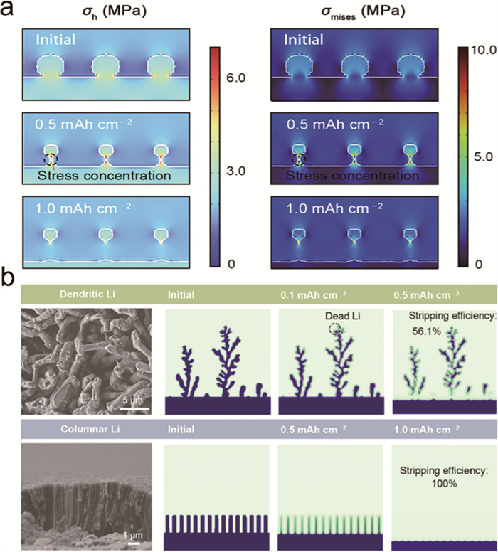
In addition to the influence of external pressure, the electrolyte modulus and the applied current density also affect the formation of dead lithium. As the electrolyte modulus increases, the generation of dead lithium decreases. In contrast, an increase in current density leads to rapid volumetric changes in the deposited lithium, resulting in stress concentrations and thereby exacerbating the formation of dead lithium. The initial morphology of lithium deposition also plays a significant role in the generation of dead lithium. Under pressure-free conditions, the tendency for dead lithium formation follows the order: Dendritic lithium > spherical lithium > columnar lithium. When external pressure is applied, dead lithium formation from dendritic lithium increases by 4.8%, while the increase for columnar lithium is only 0.6%, indicating higher pressure sensitivity of dendritic structures (Fig. 3b).
Applying appropriate stack pressure can effectively reduce the porosity of lithium deposits, mitigate the corrosion rate of lithium, and extend battery lifespan, offering considerable advantages for the reactivation of inactive lithium [122,125,127]. Wang et al. [128] found that the extent of pore formation during metal dealloying is generally regulated by the applied stack pressure, enabling stable cycling of batteries under low-pressure conditions. Although externally applied stack pressure is not directly equivalent to the internal stress within the battery, they are closely related. These findings suggest that controlling stack pressure to regulate internal stress offers a promising approach for reconstructing internal connections and revitalizing inactive lithium.
Overall, critical factors such as current density, voltage, temperature, and internal stress within batteries significantly influence lithium deposition and stripping behavior, as well as the formation and breakdown of the SEI, which impact the accumulation and recovery of dead lithium. At present, various strategies employed for reviving dead lithium can influence the internal ion and electron transport, which often result in spatial redistribution of current density, electric field, temperature, and mechanical stress. Accordingly, the influences of stress and temperature are integral components across various strategies for reactivating dead lithium.
In recent years, a variety of approaches for reviving inactive lithium have been reported. From the perspective of industrial applications, this review focuses on strategies involving the application of current/voltage pulses, electric field relaxation, and the introduction of redox mediators.
During the charge-discharge cycles of LIBs, continuous SEI formation and the accumulation of electrically isolated lithium (i-Li) are unavoidable. These processes not only contribute to the generation of inactive lithium in LMBs, but also leads to the formation of dead lithium in graphite anode-based LIBs under fast charging and overcharging conditions, ultimately resulting in capacity loss and shortened cycle life [129,130]. Currently, pulse-induced and relaxation-based recovery mechanisms primarily include: (1) Calendar ageing in the discharged state (static relaxation after discharge), (2) rapid pulse-induced restoration of electrical connectivity for dead lithium, and (3) short-term static relaxation following charging, as illustrated in Fig. 4.
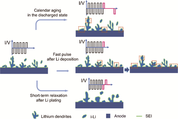
In the case of calendar ageing in the discharged state, the dissolution of the SEI occurs, which increases the opportunities for electrically isolated lithium (i-Li) to regain electrical connectivity during subsequent charging processes. In the rapid pulse-induced reconnection mechanism, short discharge pulses applied immediately after lithium deposition can promote the migration of electrically i-Li toward the anode. A critical aspect of this process is whether the SEI encapsulating the i-Li dissolves upon contact with either the anode bulk or surface dendrites, which facilitates the restoration of electrical pathways. During the short-term static relaxation period following charging, the SEI predominantly consists of stable inorganic components. The concentration gradient of Li+ shifts from the dendrite tip to its lateral sides, leading to the localized stripping of Li+ from the tip and its subsequent deposition onto the lateral sides. As a result, the lithium dendrites thicken, their tips gradually smooth out, thereby reducing the formation of dead lithium.
Up to now, several key strategies have been proposed for recovering inactive lithium in LIBs (Fig. 5), including fast pulse after Li deposition, self-heating–induced healing of lithium dendrites, pulse-induced dielectrophoresis, redox mediators, calendar ageing in the discharged state, and short-term relaxation after lithium plating.
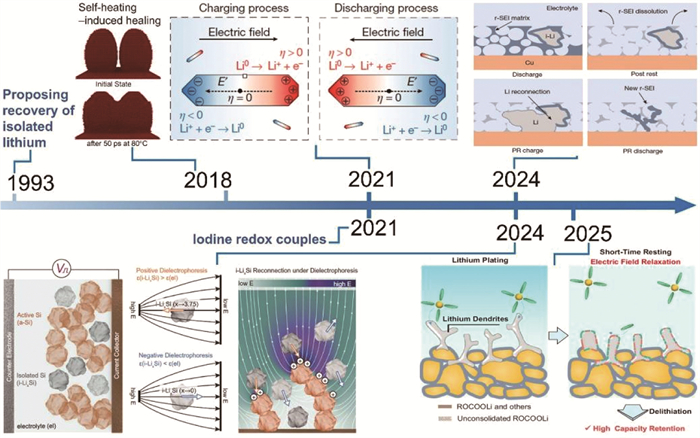
In 1993, Arakawa et al. [131] observed that lithium dendrites could grow from electrically i-Li during discharge, forming conductive bridges that reconnected i-Li with the bulk lithium anode. They proposed that utilizing the voltage gradient between lithium anode and i-Li, high-rate discharge could promote the recombination of isolated lithium with the anode, which extends the battery’s cycle life. They subsequently confirmed this hypothesis through experiments. During low-rate discharge, the current preferentially passes through the relatively low-impedance regions of the SEI, while the overpotential generated by constant-current discharge may not be sufficient to strip the deposited lithium through the high-impedance SEI domains.
Liu et al. [132] employed an in-situ optical electrochemical cell with an isolated-lithium island between the LiNi0.5Mn0.3Co0.2O2 (NMC532) cathode and lithium metal anode to observe the morphological evolution of island-shaped electrically i-Li during electrochemical processes. This observation provides direct evidence for the recovery of i-Li, contributing to the longevity of the Li anode. During battery operation, the migration of cations and anions between electrodes creates an electric potential gradient across the electrolyte, inducing polarization of i-Li and generating local overpotential (η). During charging (Li+ intercalation from cathode to anode), the side of i-Li facing the cathode experiences a negative overpotential (η < 0), promoting selective electroreduction of Li+ and Li plating on its surface. Simultaneously, the anode-facing side experiences a positive overpotential (η > 0), which facilitates electrochemical dissolution of lithium. This different electrochemical behavior exerts a net migratory force on i-Li, propelling it toward the cathode. During discharge (Li+ deintercalation from anode to cathode), the reversed electric field direction induces i-Li migration toward the anode. Four-electrode coin cell experiments revealed a strong correlation between the overpotential and applied current density. The potential gradient within the electrolyte can induce significant overpotential on i-Li to drive Li plating/stripping, especially under moderate current densities [133]. Furthermore, the recovery efficiency of i-Li closely correlates with the stripping current in Li||Cu half-cells (Fig. 6a). The Li||NMC532 cell with activation exhibits better cycling stability than that without activation, which can be attributed to the partial recovery of dead Li (Fig. 6b).
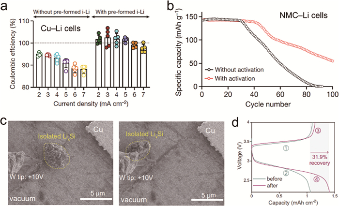
Notably, Yang et al. [134] employed voltage pulses to re-establish electrical contact between isolated lithium-silicon (i-LixSi) particles and the conductive network. The motion of these i-LixSi particles under a non-uniform electric field was directly observed via in-situ scanning electron microscopy (SEM) (Fig. 6c). Operando observations from the optical cell further confirmed the evident movement of i-LixSi particles within the electrolyte under the voltage pulse. The capacity recovery mechanism is experimentally identified as dielectrophoresis (DEP), which is the movement of electrically neutral isolated LixSi particles driven by localized nonuniform electric fields. In a Si||LFP full cell, a capacity recovery of 31.9% was achieved after applying the voltage pulse at the end of the 20th delithiation cycle, demonstrating that pulse-induced recovery is applicable to practical full-cell systems (Fig. 6d).
As research on the revival of “dead lithium” advances, significant insights have been gained into the microscopic effects of pulse application within LIBs. It has been experimentally validated that applying voltage or current pulses can effectively restore battery capacity, with the reactivation of dead lithium identified as a key mechanism contributing to this recovery. In Li||Li symmetric cells under high-current conditions, lithium dendrites can generate substantial localized heating, triggering extensive surface migration of Li atoms. This self-heating effect facilitates dendrite fusion and repair, resulting in a smooth lithium electrode surface. Experimental results further reveal that during high-current charge-discharge cycling, the cell impedance remains remain comparable before and after cycling, and the lithium metal surface maintains a dense, flat morphology free of dendrites [121]. It is important to emphasize that this dendrite repair under high-current charging relies on self-heating-induced dendrite fusion. As such, this approach imposes stringent requirements on cell design and manufacturing, particularly with respect to thermal management systems. Additionally, challenges arise from safety risks associated with excessive Li deposition, the accelerated capacity fading, and reduced energy efficiency. To address these challenges, battery manufacturers must possess strong competencies in electrolyte formulation, charging protocol development, and system-level integration. Additionally, high-current charging demands large amounts of instantaneous power, which exerts pressure on the electrical grid and necessitates significant capital investment in fast-charging stations and supporting infrastructure. Despite these limitations, high current enables rapid charging, achieving 80% state-of-charge (SOC) within ~30 min, which is dramatically faster than conventional 8-10 h charging protocols [135] The development of safe and efficient fast-charging technologies has become a central focus for competition among original equipment manufacturers, battery suppliers, and charging infrastructure providers.
On the other hand, capacity recovery through rapid pulse application is generally conducted during the discharge process. If recovery is limited to the discharge process, which typically occurs during end-user operation, it becomes difficult to achieve active control and scheduled intervention. An alternative approach is to incorporate discharge pulses into charging protocols or periodic maintenance routines, allowing for the revival of dead lithium under more controlled conditions. Nonetheless, recovery strategies based on discharge inherently involve trade-offs, including longer overall charging times and decreased energy efficiency. Consequently, achieving practical improvements in battery lifespan and utilization for both industrial and consumer applications requires the development of tailored charge and discharge strategies that optimize energy efficiency, extend cycle life, and enhance recovery performance.
The relaxation behavior of LIBs describes the gradual restoration of internal equilibrium, involving the redistribution of Li+ concentration gradients and variations in electrochemical potential during charging and discharging cycles. In particular, it describes the slow transient dynamics when the battery transitions between different SOCs, which significantly influence the battery performance and lifespan. Various changes in structural and chemical processes occur during the relaxation process, such as the repair of the SEI layer, redistribution of plated metallic lithium, reintegration of electrically isolated lithium, and relaxation of internal stresses. As a result, the implementation of optimized relaxation protocols significantly improves energy efficiency, power density, and cycle life of LIBs. In the course of relaxation, a dense and stable SEI layer on the anode promotes the formation of a smooth and compact Li deposition [17,136,137], which effectively suppresses parasitic reactions between the anode and electrolyte and reduces the irreversible loss of active lithium [138,139]. In contrast, when the SEI layer is prone to cracking, lithium tends to deposit in highly porous forms, such as dendritic or mossy structures. These morphologies intensify the interaction between the anode and electrolyte, accelerate the consumption of active lithium, and facilitate the formation of dead lithium [140].
Post-discharge relaxation, also referred to as calendar ageing after discharge, can help restore electrical connectivity to electrically isolated lithium, which can partially recover the battery’s capacity [140]. However, the mechanism by which this process facilitates the recovery of dead lithium remains incompletely understood. Zhang et al. [141] have demonstrated that calendar ageing occurring after discharge is capable of re-establishing electrical contact with isolated lithium, leading to an improvement in capacity retention. This observation contrasts sharply with the previously reported phenomenon of capacity degradation during calendar ageing following charging. Calendar ageing anode-free electrodes in the discharged and the charged states exposes the electrolyte to two different electrode environments during rest (Fig. 7a, left). In the discharged state, the electrolyte interacts with only i-Li and residual SEI (r-SEI) from previous cycles during rest, while active lithium remains in electrical contact with the electrode in the charged state and can react with the electrolyte during rest, leading to the decrease in active lithium capacity and the formation of excessive SEI and i-Li. Li||Cu half cells with a LHCE were subjected to three different cycling protocols: 12 h rest at open circuit voltage (OCV) in the discharged state, continuous cycling, and 12 h rest at OCV in the charged state (Fig. 7a, middle). The CE of Li||Cu half cells that rested in the discharged state showed a noticeable increase (Fig. 7a, right), indicating that resting without active lithium corrosion facilitates additional capacity recovery. The electrical reconnection between the lithium deposit and Cu electrode at the end of the first-cycle discharge could be directly observed by a pressurized operando optical setup. And then the isolated lithium deposit was almost completely stripped away by the end of the second discharge cycle, indicating the recovery of isolated lithium under continuous cycling. The recovery of inactive lithium is a dynamic process that continues throughout battery operation, and calendar ageing in the discharged state can accelerate this recovery.
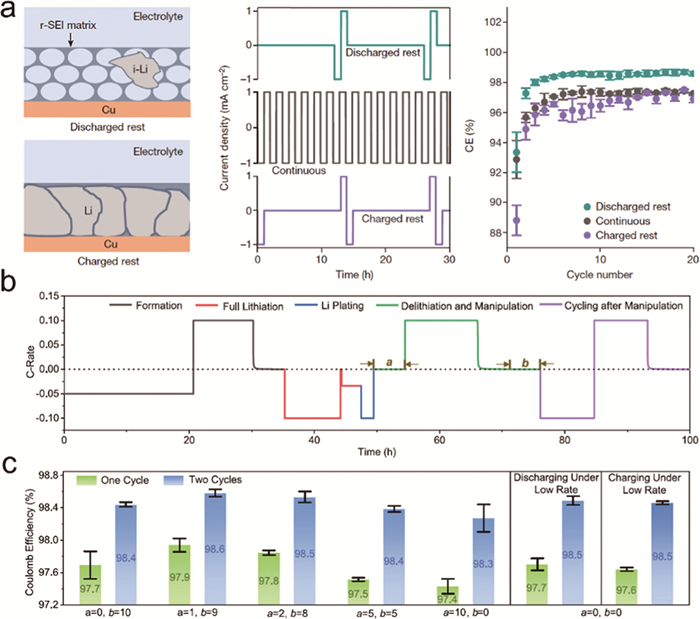
Besides, Han et al. [138] proposed an electric field relaxation strategy involving short-term rest after Li deposition, followed by discharge and another rest period to simultaneously suppress undesirable SEI growth and dead lithium formation. During short-term relaxation (corresponding to letter “a” in Fig. 7b, which represents a relatively short duration such as 1 or 2 h), the generated SEI is dense and stable, primarily composed of inorganic components (such as Li2O and LiF), which can reduce the occurrence of side reactions. Meanwhile, the Li+ concentration gradient shifts from the dendrite tips to the sides, which gradually smooths and thickens the dendrite tips, effectively reducing dendrite breakage. Nevertheless, a prolonged relaxation period (e.g., 10 h, as shown in Fig. 7c) causes an unstable SEI layer with the significant increased organic component (ROCOOLi) and more generation of dead lithium, leading to the accelerated capacity decay. In situ Raman-optical microscopy-electrochemical impedance spectroscopy (EIS) techniques were adopted to confirm the variation in SEI composition between the short and long term relaxation after lithium plating. Based on the optimized manipulation process, commercial graphite||LFP batteries achieved an improved capacity retention from 80% to 95% after 100 cycles under 3 C fast charging conditions. Compared to the discharge-rest adjustment protocol, this lithium plating manipulation protocol effectively reduces time by 80% and capacity loss by 23.8%.
Electric field relaxation can be directly integrated to the charge-discharge protocols of existing LIBs. By collaboratively considering factors such as electrolyte composition, operating temperature, stacking pressure, voltage, and current density, the recovery efficiency can be optimized through precise regulation of the calendar ageing onset and duration time, which enables the formulation of charge-discharge strategies that enhances the electrochemical performance and operational benefits.
With the rapid development of new energy vehicles globally, the application of LIBs has become increasingly complex, which promotes new demands for charging strategies. Currently, various charging methods have been developed, including constant temperature-constant voltage (CT-CV) charging, multi-step constant current (MS-CC) charging, boost charging (BC), and pulse charging (PC) [142-145]. In addition, hybrid and optimized protocols such as constant current-pulse charging (CC-PC) have emerged [146].
Notably, PC has emerged as a promising strategy for shortening charging time and enhancing battery charging efficiency. A key feature of PC is the incorporation of relaxation intervals, which promote a more uniform ion distribution. This process helps delay lithium saturation at the electrode/electrolyte interface, thereby mitigating concentration polarization and enabling more efficient Li+ intercalation into the electrode matrix. Such dynamic modulation can suppress electrolyte decomposition and limit excessive SEI growth, which collectively contribute to enhanced cycling stability [147]. Nevertheless, the underlying mechanisms by which PC regulates the evolution of lithium dendrites, dead lithium, and the SEI remain unclear. A deeper understanding is essential to achieving fast charging without sacrificing performance or accelerating battery ageing.
As the charging process is predominantly controlled by battery management systems and manufacturers, it provides an opportunity to implement targeted protocols that balance charging efficiency, battery health, and user experience. The traditional CC-CV charging protocol has been extensively applied in the charging process of LIBs, which circumvents the issue of excessively high charging current at the onset of CV charging and overcomes the tendency of overcharging that often occurs in the later stages of CC charging. Nonetheless, the CC-CV charging protocol suffers from several drawbacks, including pronounced polarization, dead lithium formation, cathode microcracking, heat accumulation, and prolonged charging times [26,148-150]. To address these issues, PC strategies have been developed to accommodate higher charging currents while incorporating rest intervals. During the rest periods, concentration polarization and ohmic polarization within the battery are mitigated, which enable smoother charging in the subsequent cycles. PC strategies offer faster charging speeds, small temperature fluctuations, and a negligible impact on battery lifespan. Building upon the PC strategies that only incorporate rest periods, more advanced protocols such as intermittent charging [151] and reflex fast charging [152] have been introduced to further expedite the charging process. Despite their advantages, these strategies still face limitations in achieving ultra-fast charging and mitigating capacity fade over extended cycling.
Recent research has confirmed that a short relaxation period following charging (or after lithium deposition) can effectively mitigate the formation of isolated lithium, optimize the composition and structure of the SEI, shorten charging time, and reduce capacity loss. Moreover, discharge pulses and relaxation periods during the idle state after discharge can also contribute to reducing capacity loss. By systematically tuning pulse charging parameters (such as pulse frequency, duty cycle, and current) under different electrolyte compositions, temperature fields, and stack pressures, it is possible to implement more intelligent and adaptive charging strategies. Leveraging neural network-based deep learning models for parameter optimization can further enable data-driven, condition-specific protocol design. Applying the aforementioned strategies in routine charging cycles or scheduled maintenance protocols offers promising pathways for enhancing capacity retention and extending battery cycle life.
Various redox mediators, such as I3−/I−, Br3−/Br−, 10-methylphenothiazine (MPT), and 2,2,6,6-tetramethylpiperidin-1-oxyl (TEMPO), have been demonstrated to effectively regenerate dead lithium through spontaneous redox reactions for compensating lithium loss in LIBs.
Most of the lithium loss in LMBs can be attributed to the formation of inactive lithium in the forms of the dead SEI and electrically isolated lithium metal debris. Jin et al. [153] found that Li2O was a key component of the dead SEI formed on the Li metal anodes in an ester-based electrolyte, and established the correlation between the SEI components with the formation of electrically isolated lithium. Based on iodine-mediated redox reactions, the I3− additive can react spontaneously with Li debris and Li2O in the dead SEI to form soluble LiI and IO3− species, resulting in the removal of inactive Li sources (Fig. 8a). Driven by a concentration gradient, the LiI acting as the Li vehicle can transfer to cathode when charged and react with the delithiated cathode (for example, Li1-xFePO4) to regenerate I3−, enabling efficient lithium storage and reuse. The IO3− serves as the oxygen vehicle to induce the formation of the Li2O-rich SEI on the fresh Li metal surface. During this reactivation process of inactive lithium, I− and I3− undergo reversible conversion, which continuously drives the above reactions and reveals the underlying mechanism by which iodine mediators reduce dead lithium. The cryogenic transmission electron microscopy (cryo-TEM) images of plated Li and SEI on a Cu grid after one cycle in the iodine-containing LiTFSI/DOL-DME electrolyte show that neat Li metal microspheres without a dead SEI and isolated Li debris grew on the Cu grid, and a smooth and dense SEI tightly covered the Li metal surface. A full-cell lithium metal battery composed of Li-metal-plated iodine-carbonized porous conidial powder (ICPC) as the anode and LFP as the cathode achieved a high capacity retention of ~80% after 1000 cycles and the CE of 99.9%. In addition, the I3−/I− redox couple has also been successfully applied to rejuvenate the inactive lithium in carbonate-based electrolytes [154].
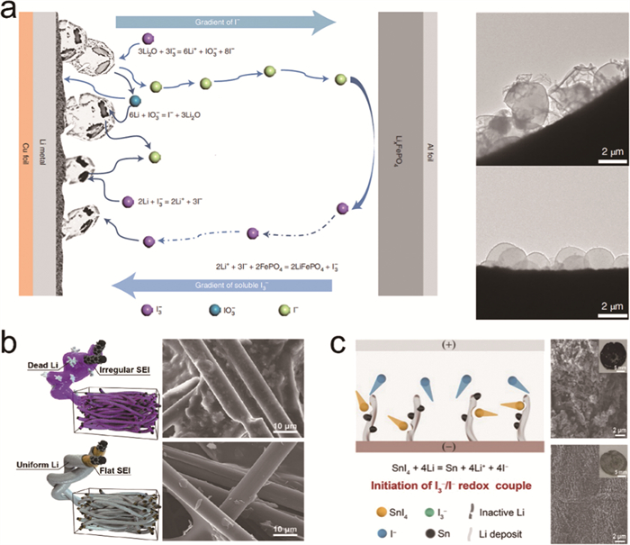
Furthermore, Dong et al. [155] introduced SrI2 into carbon paper (CP) current collectors to initiate the I3−/I− redox couple. The SEI surface is featured with SrF2 and LiF, which can prevent electrolyte decomposition, while the inner SEI layer is enriched with LiI to maintain high ionic conductivity (3.488 mS/cm), enabling efficient Li+ transfer, which synergistically suppress the growth of dead lithium. After cycling, the CP current collector without SrI2 exhibits a rough surface with abundant dead lithium and an irregular SEI layer. In sharp contrast, the SrI2-modified CP current collector presents a flat SEI layer and uniform lithium deposition, devoid of noticeable dead lithium (Fig. 8b). The assembled SrI2-modified CP||NCM532 anode-free cells show unprecedented cycling performance with only 0.09% capacity loss per cycle within 200 cycles. And in-situ Raman spectra further confirmed the formation of abundant SrF2 and LiI at the electrolyte/anode interface during the first cycle. Besides, the incorporation of SnI4 additive into the LiPF6/DMC-FEC electrolyte also result in smooth, low-contrast dendritic Li deposits after cycling without apparent dead lithium (Fig. 8c) [156]. Except for the reversible I3− and I− conversion mechanism, the formation of Sn alleviates the corrosion of I3− towards active Li. Wang et al. [39] introduced the I−-MgAl layered double hydroxide (LDH) into a carbonate-based electrolyte. By leverageing the anion exchange property of LDH, I− was displaced by NO3− to form NO3−-MgAl LDH, which not only enabled the dissolution of LiNO3 in the carbonate electrolyte, but also allowed NO3− to act as a sustained nitrogen source, optimizing the SEI composition. The displaced I− further formed the I3−/I− redox couple in the electrolyte, which promotes the recovery of inactive lithium and achieves high CE and capacity retention.
Besides, Zheng et al. [54] introduced a small amount of LiBr additive into the electrolyte as a source of the Br3−/Br− redox couple. Through a voltage-mediated electrochemical conversion, Br− was oxidized to Br3− during the activation process, which could react with Li2O in the SEI and isolated Li0 to release Li+, resulting in the restoration of reversible capacity. The capacity of fast-charging graphite||LFP full cells was increased from below 30 mAh/g to 125.5 mAh/g before and after activation.
Redox mediators can be oxidized either by charged cathode materials or by positively polarized current collectors, enabling the reactivation of dead lithium. However, the introduction of redox mediators brings severe self-discharge behaviors. To address this issue, Chen et al. [157] proposed a selection principle of redox mediators for reactivating dead Li in LMBs. Three redox mediators including ferrocene (Fc), 10-methylphenothiazine (MPT), and thianthrene (Th) were investigated in Cu||LFP batteries. Fc, with a redox potential lower than that of LFP, undergoes oxidation too readily, leading to severe self-discharge. MPT, whose redox potential lies between that of LFP and the charge cutoff voltage of the full cell, can only be oxidized by the polarized current collector, which allows for effective reactivation of dead lithium while reducing self-discharge. In contrast, the redox potential of Th is higher than the charge cutoff voltage of the full cell, which makes it ineffective for lithium reactivation. Based on these findings, TEMPO with the redox potential also lies between that of the cathode and the cell’s cutoff voltage was identified as a suitable mediator capable of efficiently reactivating dead lithium with minimal self-discharge behavior.
In addition, Zhang et al. [158] further confirmed that TEMPO that can effectively rejuvenate the accumulated dead lithium and compensate the lithium loss of anode-free LMBs (AFLMBs) during repeated cycles. Notably, TEMPO can reduce both the nucleation overpotential and voltage hysteresis, enabling uniform lithium deposition. Benefiting from the reactivation of dead lithium, suppression of lithium dendrites, and uniform lithium deposition, AFLMBs incorporating TEMPO exhibit improved cycling performance and higher CE. The high reversibility of TEMPO ensures its long-term effectiveness throughout the cycling process of AFLMBs. Similarly, Yang et al. [159] utilized TEMPO as a redox mediator to effectively reactivate dead lithium and suppress of lithium dendrites formation, which significantly improved the electrochemical performance of lithium-sulfur batteries. Besides, Su et al. [160] introduced phenethylamine (PEA) as an additive to reactivate the inactive lithium in lithium-sulfur (Li-S) batteries. PEA takes part in sequential reactions with inactive lithium and sulfur to generate R-LiPEA (reduction state) at the anode side and O-LiPEA (oxidation state) at the cathode side, respectively. Based on this organic polysulfide redox mechanism, the cycle life of Li-S batterie was effectively prolonged from 128 to 185 cycles, while maintained a high CE of 96%.
Despite these promising advances, the reactivation processes rely on the internal energy of cells, which introduce a critical trade-off between energy consumption and performance enhancement, and this inherent limitation may hinder practical applications. More importantly, these redox mediators primarily react spontaneously with the Li2O, Li2S, and dead lithium, while their efficacy in removing other components (such as LiF, LiOH, Li2CO3, and organic lithium salts) remains unclear. Experimental observations reveal that these non-reactive residues tend to accumulate on the electrode surface over extended cycling, further compromising performance. Additionally, the implementation of redox mediators typically requires material modifications and system-level adjustments, which poses significant challenges for directly integration into existing battery architectures challenging. Bridging the gap between laboratory breakthroughs and industrial-scale implementation remains a formidable journey.
The formation and accumulation of inactive materials is a major cause of the capacity loss. This review provides a comprehensive overview of strategies for reactivating inactive lithium in LMBs, graphite-based LIBs, and silicon-based LIBs. It systematically summarizes multiple advanced approaches including pulse induction, electric field relaxation, and redox mediators, which offers a cutting-edge perspective and research paradigm for reviving dead lithium.
During the pulse-induced recovery of inactive lithium, the changes within the battery are complex. Pulse currents or voltages influence the transport mechanism at the electrode/electrolyte interphase. The role of the structure and composition of SEI in facilitating the reactivation of inactive lithium remains insufficiently understood. Moreover, the effects of electrode structure and electrolyte solvation structure on the recovery of inactive lithium require further investigation, as these factors critically influence the control and efficiency of the revival process. For LIBs, pulse-induced recovery of inactive lithium typically occurs under high-voltage or high-current discharge conditions, which necessitates a careful trade-off between energy loss and capacity restoration. In particular, the pulse current induces the cell self-heating, which can alleviate the capacity degradation at low temperatures. Inspired by the rejuvenation of isolated LixSi alloy, the pulse voltage can be expected to trigger the polarization and movement of inactive lithium for recovery in localized nonuniform electric fields enabled by dielectrophoresis. Calendar ageing under discharge conditions presents similar challenges. Controlling SEI dissolution during this process remains a critical issue. Furthermore, the influence of key factors such as electrolyte solvation structure on the recovery of inactive lithium remains unclear. Short-term electric field relaxation post-charging offers another approach to modulate SEI stability and smooth lithium dendrite structures. However, the transformation pathways of inactive lithium during this relaxation and the potential for its reactivation warrant further investigation. Besides, different strategies should be integrated to improve the recovery efficiency of inactive lithium. For instance, suitable pulse current and relaxation time during the pulse discharge process can further increase the energy and power densities of the battery. Understanding the relevant mechanism is crucial for achieving precise regulation of inactive lithium recovery and ultimately extending battery lifespan.
From the perspective of industrial applications, this review also evaluates the practical feasibility of pulse induction, electric field relaxation, and redox mediators. Among them, pulses induction and electric field relaxation are more compatible with existing battery systems and hold greater potentials for practical implementation. However, their deployment requires careful integration with charging management protocols, thermal regulation, modeling frameworks, circuits, and power supplies, which pose new challenges for industrial-scale adoption.
By integrating parameters such as current density, voltage, internal temperature filed, and pressure within the battery, and leveraging neural networks across various electrolyte systems, it is possible to achieve multi-parameter coupling and develop intelligent charging strategies that enhance the energy utilization of LIBs. Advanced characterization techniques for revealing inactive lithium should be developed to synchronously observe its chemical and structural changes at time and spatial scales, especially for solid-state batteries. Furthermore, the insights and solutions discussed herein may also be extended to other batteries systems with high-capacity electrode materials, such as other alkali metal-ion batteries, alkali metal-sulfur batteries, and redox flow batteries.
Pu Guo: Writing – review & editing, Writing – original draft, Methodology, Investigation. Dandan Yu: Writing – review & editing, Validation, Supervision, Project administration. Yuzhen Zhao: Supervision, Resources, Project administration. Hua Wang: Validation, Supervision, Resources, Conceptualization.
The authors declare that they have no known competing financial interests or personal relationships that could have appeared to influence the work reported in this paper.
The authors acknowledge the financial support of the Open Project of State Key Laboratory of Environment-Friendly Energy Materials (No. 23kfhg09), Key Laboratory Open Fund Project of Jiangxi Province for Persistent Pollutants Control and Resources Recycle (No. ES202480187), the Natural Science Basic Research Plan in Shaanxi Province of China (No. 2024JC-YBMS-342), the Natural Science Foundation of Shaanxi Provincial Department of Education (Nos. 23JP185 and 24JP199), the Science and Technology Plan Project of Xi’an (No. 24GXFW0091), the Youth Innovation Team of Shanxi, Natural Science Foundation of Shaanxi Provincial Department of Education (No. 24JK0700), the Natural Science Basic Research Program of Shaanxi Province (No. 2025JC-YBQN-172), and the Scientific Research Foundation for High-Level Talents of Xijing University (No. XJ24B10).
G. Yang, Z. Hao, C. Fang, et al., Chin. Chem. Lett. 36 (2025) 111185. doi: 10.1016/j.cclet.2025.111185
S. Xin, X. Zhang, L. Wang, et al., Sci. China Chem. 67 (2024) 13–42. doi: 10.1007/s11426-023-1908-9
J.H. Kim, N.Y. Kim, Z. Ju, et al., Nat. Energy 10 (2025) 295–307. doi: 10.1038/s41560-025-01720-0
E.S. Patheria, P. Guzman, L.S. Soldner, et al., J. Am. Chem. Soc. 147 (2025) 9786–9799. doi: 10.1021/jacs.4c18440
L. Wang, G. Liu, R. Xu, et al., Adv. Energy Mater. 13 (2023) 2203999. doi: 10.1002/aenm.202203999
Y.J. Ha, S. Roh, B.K. Park, et al., Adv. Energy Mater. 14 (2024) 2402032. doi: 10.1002/aenm.202402032
Y. Chen, M. Li, Y. Jie, et al., Joule 9 (2025) 101885. doi: 10.1016/j.joule.2025.101885
M. Nishijima, T. Ootani, Y. Kamimura, et al., Nat. Commun. 5 (2014) 4553. doi: 10.1038/ncomms5553
M. Han, J. Liu, K. Zheng, et al., Adv. Energy Mater. 14 (2024) 2401065. doi: 10.1002/aenm.202401065
Z. Xiao, X. Liu, F. Hai, et al., Angew. Chem. Int. Ed. 64 (2025) e202503693. doi: 10.1002/anie.202503693
M. Li, J. Yuan, K. Wang, et al., Energy Storage Mater. 77 (2025) 104163. doi: 10.1016/j.ensm.2025.104163
Y. Yang, N. Yao, Y.X. Yao, et al., Adv. Energy Mater. 15 (2025) 2403183. doi: 10.1002/aenm.202403183
J. Chen, H. Lan, S. Wang, et al., J. Am. Chem. Soc. 147 (2025) 2393–2402. doi: 10.1021/jacs.4c12126
C. Hu, L. Dai, F. Huang, et al., Angew. Chem. Int. Ed. 64 (2025) e202508584. doi: 10.1002/anie.202508584
Y. Lin, W. Hu, M. Ding, et al., Adv. Energy Mater. 14 (2024) 2400894. doi: 10.1002/aenm.202400894
X. Gu, Q. Zhang, Q. Chen, et al., Adv. Mater. 37 (2025) 2501448. doi: 10.1002/adma.202501448
B. Jagger, M. Pasta, Joule 7 (2023) 2228–2244. doi: 10.1016/j.joule.2023.08.007
W. Yu, K.Y. Lin, D.T. Boyle, et al., Nat. Chem. 17 (2025) 246–255. doi: 10.1038/s41557-024-01689-5
G.X. Li, V. Koverga, A. Nguyen, et al., Nat. Energy 9 (2024) 817–827. doi: 10.1038/s41560-024-01519-5
C. Wang, Y. Xie, Y. Huang, et al., Angew. Chem. Int. Ed. 63 (2024) e202402301. doi: 10.1002/anie.202402301
S.K. Heiskanen, J. Kim, B.L. Lucht, Joule 3 (2019) 2322–2333. doi: 10.1016/j.joule.2019.08.018
Y. Yang, L. Xu, C. Yan, et al., Energy Lab 1 (2023) 220011.
R. Wang, L. Wang, R. Liu, et al., ACS Nano 18 (2024) 2611–2648. doi: 10.1021/acsnano.3c08712
Q. Zhu, L. Cheng, X. Sun, et al., Adv. Mater. 37 (2025) 2419041. doi: 10.1002/adma.202419041
D. Qiao, X. Wei, J. Zhu, et al., Cell Rep. Phys. Sci. 5 (2024) 101961. doi: 10.1016/j.xcrp.2024.101961
X.R. Chen, C. Yan, J.F. Ding, et al., J. Energy Chem. 62 (2021) 289–294. doi: 10.3390/fi13110289
M. Tao, X. Chen, H. Lin, et al., ACS Nano 17 (2023) 24104–24114. doi: 10.1021/acsnano.3c09120
Y. Xiang, M. Tao, X. Chen, et al., Nat. Commun. 14 (2023) 177. doi: 10.1038/s41467-022-35779-0
R. Zhang, X. Shen, Y.T. Zhang, et al., J. Energy Chem. 71 (2022) 29–35. doi: 10.1016/j.jechem.2021.12.020
J.F. Ding, R. Xu, X.X. Ma, et al., Angew. Chem. Int. Ed. 61 (2022) e202115602. doi: 10.1002/anie.202115602
Y.Y. Wang, Y.N. Wang, N. Yao, et al., J. Energy Chem. 95 (2024) 644–650. doi: 10.1021/acs.jctc.3c01263
H. Wang, X. Yan, R. Zhang, et al., Nat. Nanotechnol. 20 (2025) 1034–1042. doi: 10.1038/s41565-025-01935-y
M. He, L.G. Hector, F. Dai, et al., Nat. Energy 9 (2024) 1199–1205. doi: 10.1038/s41560-024-01624-5
S. Huo, L. Wang, B. Su, et al., Adv. Mater. 36 (2024) 2411757. doi: 10.1002/adma.202411757
G. Xu, M. Wang, Y. Song, et al., Adv. Funct. Mater. 35 (2025) 2412614. doi: 10.1002/adfm.202412614
T. Lee, M.J. Seong, H.C. Ahn, et al., Proc. Natl. Acad. Sci. U. S. A. 122 (2025) e2417053121. doi: 10.1073/pnas.2417053121
N. Kim, Y. Kim, J. Sung, et al., Nat. Energy 8 (2023) 921–933. doi: 10.1038/s41560-023-01333-5
Y. Gao, W. Ye, K. Qiu, et al., Adv. Mater. 35 (2023) 2306501. doi: 10.1002/adma.202306501
F. Wang, Z. Zheng, Z. Wen, et al., Sci. Bull. 70 (2025) 2493–2503. doi: 10.1016/j.scib.2025.04.016
Z. Zhu, X. Li, X. Qi, et al., Nano Micro Lett. 15 (2023) 234. doi: 10.1007/s40820-023-01205-3
L. Cheng, H. Lan, Y. Gao, et al., Angew. Chem. Int. Ed. 63 (2024) e202315624. doi: 10.1002/anie.202315624
S. Chen, G. Wu, H. Jiang, et al., Nature 638 (2025) 676–683. doi: 10.1038/s41586-024-08465-y
Q. Nie, W. Wan, Y. Mei, et al., Adv. Funct. Mater. 35 (2025) 2422034. doi: 10.1002/adfm.202422034
B. Zhou, A. Bonakdarpour, I. Stoševski, et al., Prog. Mater Sci. 130 (2022) 100996. doi: 10.1016/j.pmatsci.2022.100996
P. Molaiyan, M. Abdollahifar, B. Boz, et al., Adv. Funct. Mater. 34 (2024) 2311301. doi: 10.1002/adfm.202311301
J. Zhao, M. Tang, H. Lan, et al., Energy Storage Mater. 70 (2024) 103480. doi: 10.1016/j.ensm.2024.103480
J. Chen, D. Yu, Q. Zhu, et al., Adv. Mater. 34 (2022) 2205678. doi: 10.1002/adma.202205678
G.X. Lu, Q.Q. Qiao, M.T. Zhang, et al., Sci. Adv. 10 (2024) eado7348. doi: 10.1126/sciadv.ado7348
Y. Yu, K. Long, S. Huang, et al., Adv. Funct. Mater. 35 (2025) 2424386. doi: 10.1002/adfm.202424386
P. Xiao, X. Yun, Y. Chen, et al., Chem. Soc. Rev. 52 (2023) 5255–5316. doi: 10.1039/d3cs00151b
K. Nishikawa, T. Mori, T. Nishida, et al., J. Electroanal. Chem. 661 (2011) 84–89. doi: 10.1016/j.jelechem.2011.06.035
W. Yuan, W. Peng, C. Wu, et al., Adv. Energy Mater. 15 (2025) 2405907. doi: 10.1002/aenm.202405907
Y.F. Liu, H.X. Liu, Y.F. Zhu, et al., Adv. Mater. 37 (2025) 2417540. doi: 10.1002/adma.202417540
M. Zheng, T. Liu, J. Wu, et al., Adv. Mater. 37 (2025) 2414207. doi: 10.1002/adma.202414207
X. Shen, R. Zhang, P. Shi, et al., Fundam. Res. 4 (2024) 1498–1505. doi: 10.1016/j.fmre.2022.11.005
Q. Zhu, J. Wang, L. Wu, et al., Natl. Sci. Rev. 12 (2025) nwaf124. doi: 10.1093/nsr/nwaf124
Y. Feng, L. Zhou, H. Ma, et al., Energy Environ. Sci. 15 (2022) 1711–1759. doi: 10.1039/d1ee03292e
Q. Zhao, S. Stalin, L.A. Archer, Joule 5 (2021) 1119–1142. doi: 10.1016/j.joule.2021.03.024
J.B. Goodenough, Y. Kim, Chem. Mater. 22 (2010) 587–603. doi: 10.1021/cm901452z
M.M. Bela, M. Mense, S. Greiwe, et al., J. Mater. Chem. A 13 (2025) 7476–7487. doi: 10.1039/d4ta06366j
J. Becking, A. Gröbmeyer, M. Kolek, et al., Adv. Mater. Interfaces 4 (2017) 1700166. doi: 10.1002/admi.201700166
X.B. Cheng, S.J. Yang, Z. Liu, et al., Adv. Mater. 36 (2024) 2307370. doi: 10.1002/adma.202307370
A.J. Sanchez, N.P. Dasgupta, J. Am. Chem. Soc. 146 (2024) 4282–4300. doi: 10.1021/jacs.3c05715
Z. Zheng, X. Liu, X.Q. Zhang, et al., Angew. Chem. Int. Ed. 64 (2025) e202507387. doi: 10.1002/anie.202507387
I. Yoshimatsu, T. Hirai, J.i. Yamaki, J. Electrochem. Soc. 135 (1988) 2422. doi: 10.1149/1.2095351
J. Zhang, A.F. Chadwick, P.W. Voorhees, Cell Rep. Phys. Sci. 6 (2025) 102360. doi: 10.1016/j.xcrp.2024.102360
G. Gachot, P. Ribière, D. Mathiron, et al., Anal. Chem. 83 (2011) 478–485. doi: 10.1021/ac101948u
X. Zhang, P. Xu, J. Duan, et al., Nat. Commun. 15 (2024) 536. doi: 10.1038/s41467-024-44858-3
W. Fang, Z. Wen, L. Chen, et al., Nano Energy 104 (2022) 107881. doi: 10.1016/j.nanoen.2022.107881
J. Liu, S. Ihuaenyi, R. Kuphal, et al., J. Electrochem. Soc. 170 (2023) 010535. doi: 10.1149/1945-7111/acb3fe
M. Yeddala, L. Rynearson, B.L. Lucht, ACS Energy Lett. 8 (2023) 4782–4793. doi: 10.1021/acsenergylett.3c01709
H. Wang, Z. Yu, X. Kong, et al., Joule 6 (2022) 588–616. doi: 10.1016/j.joule.2021.12.018
Y.H.T. Tran, K. An, D.T.T. Vu, et al., ACS Energy Lett. 10 (2025) 356–370. doi: 10.1021/acsenergylett.4c02860
X. Liu, X. Dong, H. Adenusi, et al., Nat. Rev. Chem. 9 (2025) 415–426. doi: 10.1038/s41570-025-00714-6
G.M. Hobold, J. Lopez, R. Guo, et al., Nat. Energy 6 (2021) 951–960. doi: 10.1038/s41560-021-00910-w
X. Zheng, L. Huang, X. Ye, et al., Chem 7 (2021) 2312–2346. doi: 10.1016/j.chempr.2021.02.025
J. Zhou, Y. Wang, J. Wang, et al., Energy Storage Mater. 50 (2022) 47–54. doi: 10.1117/12.2631871
T. Yang, L. Li, J. Zou, et al., Adv. Funct. Mater. 34 (2024) 2404945. doi: 10.1002/adfm.202404945
H. Fu, X. Ye, Y. Zhang, et al., Adv. Energy Mater. 14 (2024) 2401961. doi: 10.1002/aenm.202401961
Y. Zhao, T. Zhou, D. Baster, et al., ACS Energy Lett. 8 (2023) 3180–3187. doi: 10.1021/acsenergylett.3c01004
S. Kim, M. Kim, J.W. Choi, Nat. Energy 9 (2024) 769–770. doi: 10.1038/s41560-024-01528-4
Z. Wang, Y. Wang, B. Li, et al., Angew. Chem. Int. Ed. 61 (2022) e202206682. doi: 10.1002/anie.202206682
N. Li, X. Han, X. Cui, et al., Adv. Funct. Mater. 35 (2025) 2409431. doi: 10.1002/adfm.202409431
Q. Li, G. Liu, Y. Chen, et al., Adv. Funct. Mater. 35 (2025) 2420327. doi: 10.1002/adfm.202420327
J.A. Mennel, D. Chidambaram, Front. Energy 17 (2023) 43–71. doi: 10.1007/s11708-022-0853-5
Y. Yang, L.G. Yu, Y.X. Huang, et al., Angew. Chem. Int. Ed. 64 (2025) e202503616. doi: 10.1002/anie.202503616
Z. Li, Y.X. Yao, S. Sun, et al., Angew. Chem. Int. Ed. 62 (2023) e202303888. doi: 10.1002/anie.202303888
Y. Qin, S.G. Choi, L. Mason, et al., Chem. Sci. 15 (2024) 9224–9239. doi: 10.1039/d4sc02266a
P. Lai, B. Huang, X. Deng, et al., Chem. Eng. J. 461 (2023) 141904. doi: 10.1016/j.cej.2023.141904
Y. Yang, N. Yao, Y.C. Gao, et al., Angew. Chem. Int. Ed. 64 (2025) e202505212. doi: 10.1002/anie.202505212
H.K. Bergstrom, B.D. McCloskey, ACS Energy Lett. 9 (2024) 373–380. doi: 10.1021/acsenergylett.3c01662
X. Cao, H. Jia, W. Xu, et al., J. Electrochem. Soc. 168 (2021) 010522. doi: 10.1149/1945-7111/abd60e
Z. Piao, X. Wu, H.R. Ren, et al., J. Am. Chem. Soc. 145 (2023) 24260–24271. doi: 10.1021/jacs.3c08733
C. Wang, K. Wan, P. Liu, et al., Angew. Chem. Int. Ed. 64 (2025) e202506083. doi: 10.1002/anie.202506083
C.M. Efaw, Q. Wu, N. Gao, et al., Nat. Mater. 22 (2023) 1531–1539. doi: 10.1038/s41563-023-01700-3
H. Cheng, Q. Sun, L. Li, et al., ACS Energy Lett. 7 (2022) 490–513. doi: 10.1021/acsenergylett.1c02425
L. Cheng, Y. Wang, J. Yang, et al., Adv. Funct. Mater. 33 (2023) 2212349. doi: 10.1002/adfm.202212349
Z. Li, L. Wang, X. Huang, et al., Adv. Funct. Mater. 34 (2024) 2408319. doi: 10.1002/adfm.202408319
C. Shen, D. Guan, W. Liu, et al., Adv. Funct. Mater. 35 (2025) 2503713. doi: 10.1002/adfm.202503713
M. Zhou, W. Liu, Q. Su, et al., ACS Nano 18 (2024) 32959–32972. doi: 10.1021/acsnano.4c13203
J. Min, S.M. Bak, Y. Zhang, et al., Nat. Nanotechnol. 20 (2025) 787–797. doi: 10.1038/s41565-025-01885-5
J. Yang, S. Wang, S. Song, et al., Adv. Mater. 37 (2025) 2501807. doi: 10.1002/adma.202501807
J. Wang, Y. Zhou, Y. Zhuo, et al., Chem. Sci. 16 (2025) 552–574. doi: 10.1039/d4sc06630h
J. Zhou, Y. Ding, Y. Wang, et al., J. Colloid Interface Sci. 657 (2024) 502–510. doi: 10.1016/j.jcis.2023.12.012
S. Liu, J. Xia, W. Zhang, et al., Angew. Chem. Int. Ed. 61 (2022) e202210522. doi: 10.1002/anie.202210522
Y. Wang, Z. Li, Y. Hou, et al., Chem. Soc. Rev. 52 (2023) 2713–2763. doi: 10.1039/d2cs00873d
Y. Li, J. Wang, Y. Wang, et al., Adv. Mater. 37 (2025) 2419764. doi: 10.1002/adma.202419764
Y. Wang, H. Lan, S. Dong, et al., Adv. Funct. Mater. 34 (2024) 2315498. doi: 10.1002/adfm.202315498
G.A. Ferrero, G. Åvall, K. Janßen, et al., Chem. Rev. 125 (2025) 3401–3439. doi: 10.1021/acs.chemrev.4c00805
X. Han, L. Lu, Y. Zheng, et al., eTransportation 1 (2019) 100005. doi: 10.1016/j.etran.2019.100005
J. Chen, D. An, S. Wang, et al., Angew. Chem. Int. Ed. 62 (2023) e202307122. doi: 10.1002/anie.202307122
W. Cai, C. Yan, Y.X. Yao, et al., Angew. Chem. Int. Ed. 60 (2021) 13007–13012. doi: 10.1002/anie.202102593
J. Qian, W.A. Henderson, W. Xu, et al., Nat. Commun. 6 (2015) 6362. doi: 10.1038/ncomms7362
Z. Li, Y.X. Yao, M. Zheng, et al., Angew. Chem. Int. Ed. 64 (2025) e202409409. doi: 10.1002/anie.202409409
J. Fan, C. Liu, N. Li, et al., Nature 641 (2025) 639–645. doi: 10.1038/s41586-025-08785-7
S. Zhu, L. Yang, J. Wen, et al., J. Power Sources 516 (2021) 230669. doi: 10.1016/j.jpowsour.2021.230669
Y. Ou, D. Zhu, P. Zhou, et al., Angew. Chem. Int. Ed. 64 (2025) e202504632. doi: 10.1002/anie.202504632
M. Tang, S. Dong, J. Wang, et al., Nat. Commun. 14 (2023) 6006. doi: 10.1038/s41467-023-41778-6
W. Zhang, Y. Lu, Q. Feng, et al., Nat. Commun. 16 (2025) 3344. doi: 10.1038/s41467-025-58627-3
T. Sun, T. Shen, Y. Zheng, et al., Electrochim. Acta 425 (2022) 140701. doi: 10.1016/j.electacta.2022.140701
L. Li, S. Basu, Y. Wang, et al., Science 359 (2018) 1513–1516. doi: 10.1126/science.aap8787
B. Lu, W. Li, D. Cheng, et al., Adv. Energy Mater. 12 (2022) 2202012. doi: 10.1002/aenm.202202012
X. Lin, Y. Shen, Y. Yu, et al., Adv. Energy Mater. 14 (2024) 2303918. doi: 10.1002/aenm.202303918
X. Duan, Y. Li, K. Huang, et al., Sci. Bull. 70 (2025) 914–922. doi: 10.1016/j.scib.2025.01.030
D. Liu, B. Wu, Y. Xu, et al., Nat. Energy 9 (2024) 559–569. doi: 10.1038/s41560-024-01488-9
W. Li, F. Yang, K. Wang, et al., J. Electrochem. Soc. 172 (2025) 010512. doi: 10.1149/1945-7111/ada062
C. Fang, B. Lu, G. Pawar, et al., Nat. Energy 6 (2021) 987–994. doi: 10.1038/s41560-021-00917-3
C. Wang, Y. Liu, W.J. Jeong, et al., Nat. Mater. 24 (2025) 907–916. doi: 10.1038/s41563-025-02198-7
Y. Peng, M. Ding, K. Zhang, et al., ACS Energy Lett. 9 (2024) 6022–6028. doi: 10.1021/acsenergylett.4c02898
E. Adhitama, F. Demelash, T. Brake, et al., Adv. Energy Mater. 14 (2024) 2303468. doi: 10.1002/aenm.202303468
M. Arakawa, S.I. Tobishima, Y. Nemoto, et al., J. Power Sources 43 (1993) 27–35. doi: 10.1016/0378-7753(93)80099-B
F. Liu, R. Xu, Y. Wu, et al., Nature 600 (2021) 659–663. doi: 10.1038/s41586-021-04168-w
B.S. Vishnugopi, P.P. Mukherjee, Joule 6 (2022) 291–293. doi: 10.1016/j.joule.2022.01.014
Y. Yang, S. Biswas, R. Xu, et al., Science 386 (2024) 322–327. doi: 10.1126/science.adn1749
J. Zhao, H. Lan, G. Yang, et al., Angew. Chem. Int. Ed. 64 (2025) e202501208. doi: 10.1002/anie.202501208
Q. Zhu, D. Yu, J. Chen, et al., Joule 8 (2024) 482–495. doi: 10.1016/j.joule.2024.01.010
J. Tan, J. Matz, P. Dong, et al., Adv. Energy Mater. 11 (2021) 2100046. doi: 10.1002/aenm.202100046
X. Han, S. Mao, Y. Wang, et al., Nat. Commun. 16 (2025) 3699. doi: 10.1038/s41467-025-58818-y
L.C. Merrill, D.M. Long, K.A. Small, et al., J. Phys. Chem. C 126 (2022) 17490–17501. doi: 10.1021/acs.jpcc.2c05385
W. Mei, Y. Zhang, Y. Li, et al., Energy Storage Mater. 66 (2024) 103193. doi: 10.1016/j.ensm.2024.103193
W. Zhang, P. Sayavong, X. Xiao, et al., Nature 626 (2024) 306–312. doi: 10.1038/s41586-023-06992-8
P. Notten, B. Veld, J.R.G. Beek, J. Power Sources 145 (2005) 89–94. doi: 10.1016/j.jpowsour.2004.12.038
M. Sabarimuthu, N. Senthilnathan, M.S. Kamalesh, Electr. Eng. 105 (2023) 4289–4309. doi: 10.1007/s00202-023-01937-w
G.J. Chen, C.L. Liu, Y.H. Liu, et al., Electronics 13 (2024) 645. doi: 10.3390/electronics13030645
L. Patnaik, A.V.J.S. Praneeth, S.S. Williamson, IEEE Trans. Ind. Electron. 66 (2019) 1059–1067. doi: 10.1109/tie.2018.2833038
M. Leng, C. Hu, Z. Zhou, et al., eTransportation 24 (2025) 100402. doi: 10.1016/j.etran.2025.100402
J. Guo, Y. Xu, M. Exner, et al., Adv. Energy Mater. 14 (2024) 2400190. doi: 10.1002/aenm.202400190
Z. Li, H. Yi, W. Ding, et al., Adv. Funct. Mater. 34 (2024) 2312837. doi: 10.1002/adfm.202312837
J.Y. Park, M. Jo, S. Hong, et al., Adv. Energy Mater. 12 (2022) 2201151. doi: 10.1002/aenm.202201151
J.F. Ding, R. Xu, X.X. Ma, et al., Angew. Chem. Int. Ed. 61 (2022) e202115602. doi: 10.1002/anie.202115602
Q. Li, T. Chen, Battery Bimonthly 27 (1997) 266–268 281.
M. Bayati, M. Abedi, H. Hosseinian, et al., J. Energy Storage 12 (2017) 108–120. doi: 10.1016/j.est.2017.03.013
C. Jin, T. Liu, O. Sheng, et al., Nat. Energy 6 (2021) 378–387. doi: 10.1038/s41560-021-00789-7
Z. Wen, W. Fang, X. Wu, et al., Adv. Funct. Mater. 32 (2022) 2204768. doi: 10.1002/adfm.202204768
L. Dong, S. Zhong, B. Yuan, et al., Angew. Chem. Int. Ed. 62 (2023) e202301073. doi: 10.1002/anie.202301073
C.B. Jin, X.Q. Zhang, O.W. Sheng, et al., Angew. Chem. Int. Ed. 60 (2021) 22990–22995. doi: 10.1002/anie.202110589
J. Chen, Z. Cheng, Y. Liao, et al., Adv. Energy Mater. 12 (2022) 2201800. doi: 10.1002/aenm.202201800
Y. Zhang, J. Liu, Y. Li, et al., Adv. Funct. Mater. 33 (2023) 2301332. doi: 10.1002/adfm.202301332
R. Yang, F. Wang, W.E. Cui, et al., Energy Storage Mater. 75 (2025) 104030. doi: 10.1016/j.ensm.2025.104030
L.L. Su, M.X. Wu, S.Y. Sun, et al., ACS Energy Lett. 10 (2025) 313–319. doi: 10.1021/acsenergylett.4c03177

Figure 2
(a) A schematic illustration of SEI formation.

Figure 3 (a) The simulated distribution of hydrostatic stress (σh) and von Mises stress (σmises) under the external pressure. (b) SEM images of dendritic Li and columnar Li, and the corresponding simulated stripping process. Reproduced with permission [55]. Copyright 2024, KeAi.

Figure 4 Schematic diagrams of dead lithium and dendritic evolution under three post-cycling treatments: Calendar ageing in the discharged state, fast pulse after Li deposition, and short-term relaxation after Li plating.

Figure 5 Recent progress in inactive lithium recovery, including smart strategies of high-rate discharge (proposing recovery of isolated lithium), self-heating–induced healing of lithium dendrites, fast pulse, iodine redox couples, calendar ageing in the discharged state, pulse-induced dielectrophoretic, and short-term relaxation after lithium plating. Reproduced with permission [131]. Copyright 1993, Elsevier B.V. Reproduced with permission [121]. Copyright 2018, The Authors. Reproduced with permission [132]. Copyright 2021, Springer Nature. Reproduced with permission [153] Copyright 2021, Springer Nature. Reproduced with permission [141]. Copyright 2021, Springer Nature. Reproduced with permission [134]. Copyright 2024, Science. Reproduced with permission [138]. Copyright 2025, The Author(s).

Figure 6 (a) CEs of Li||Cu cells with and without pre-formed i-Li under different stripping currents. (b) Specific capacity of Li||NMC532 cells with and without activation. (c) In-situ SEM observations of isolated LixSi movement under the non-uniform electric field. (d) Voltage-capacity profiles of Si||LFP cells before and after the voltage pulse at the 20th cycle. (a, b) Reproduced with permission [132]. Copyright 2021, Springer Nature. (c, d) Reproduced with permission [134]. Copyright 2024, Science.

Figure 7 (a) Schematic depicting the anode calendar aged in the discharged state and charged state (left). Current profiles of Li||Cu half cells undergoing post-discharge calendar ageing, continuous charge-discharge cycling, and post-charge calendar ageing (middle), respectively, and the corresponding CE during cycling (right). Reproduced with permission [141]. Copyright 2021, Springer Nature. (b) Test protocols for the manipulation processes after lithium plating. (c) The single-cycle and two-cycle capacity retention rates (CRR) under different manipulation processes. Reproduced with permission [138]. Copyright 2025, The Author(s).

Figure 8 (a) Li restoration based on iodine redox shuttling (left), and cryo-TEM image of plated Li and SEI on a Cu grid after one cycle in LiTFSI/DOL-DME (top), and high-resolution cryo-TEM image of the SEI layer on plated Li in LiTFSI/DOL-DME (bottom). Reproduced with permission [153] Copyright 2021, Springer Nature. (b) Schematic illustration (left) for the surface of CP current collectors without and with SrI2 after cycling, and SEM images (right) of CP current collectors disassembled from CP||LiNi0.5Co0.3Mn0.2O2 (NCM532) cells without and with SrI2, respectively. Reproduced with permission [155]. Copyright 2023, Wiley-VCH. (c) Schematic illustration for initiating reaction between SnI4 and Li deposits (left), and SEM images (right) of Li foils after cycling in LiPF6/DMC-FEC electrolytes without (top) and with 4.0 mmol/L SnI4 additive (bottom), respectively. Reproduced with permission [156]. Copyright 2021, Wiley-VCH.

 扫一扫看文章


扫一扫关注我们
 DownLoad:

 下载:
 下载: