Received Date:
12 August 2025 Accepted Date:
21 September 2025 Revised Date:
17 September 2025 Available Online:
15 November 2026
Abstract:
The unsatisfied energy density and power density of zinc-ion capacitors necessitate the development of carbonaceous cathodes with both functional groups and abundant porosities. In this work, a carbonyl-enriched porous carbon nanomaterial is synthesized via Scholl coupling and dual molten salt treatment using p-benzoquinone as the precursor. Theoretical analysis indicates that appropriate pore size can enhance the transport capability of [Zn(H2O)6]2+, while a high carbonyl content strengthens the chemical interaction between [Zn(H2O)6]2+ and the electrode. Experimental results reveal that the pore structure and carbonyl content are influenced by zinc chloride and iron chloride molten salts, respectively, and the use of dual molten salts synergistically optimizes the formation of abundant pore structures with appropriate sizes and high carbonyl content. Consequently, the derived CPC-FeZn exhibits the highest effective specific surface area (SSAd > 0.86nm, 1292 m2/g) and carbonyl content (3.01 at%), endowing CPC-FeZn with a specific capacitance of 256.1 F/g at 0.1 A/g, an excellent rate capability (66.7% capacitance retention at 20 A/g), and a high energy density of 91.1 Wh/kg at 80 W/kg. This work establishes CPC-FeZn as a high-performance cathode for zinc-ion capacitors, providing a design paradigm for sustainable energy storage technologies.
The escalating global energy crisis, coupled with severe environmental pollution, has intensified the demand for sustainable energy solutions [1,2]. To mitigate reliance on fossil fuels, the development of green, efficient, and renewable energy storage devices has become a pivotal strategy [3-5]. Zinc-ion capacitors (ZICs) have emerged as a promising alternative, leveraging the abundance of zinc, the inherent safety of aqueous electrolytes, and competitive theoretical capacity of 820 mAh/g and low redox potential (−0.76 V vs. SHE) [6,7]. As hybrid energy storage systems, ZICs combine a battery-type anode with a capacitor-type cathode [8,9]. One of the critical issues to improve ZICs performance lies in the development of high-performance cathodes. Typically, the cathodes for ZICs encompass diverse materials, including surface redox and intercalation pseudocapacitance compounds (e.g., metal oxides, metal nitrides, Mxene and Prussian blue analogs) and carbon-based materials [10,11]. Among these, carbon nanomaterials are particularly valued for their chemical stability, tunable structures, and versatility [12].
Efforts to enhance ZICs performance using carbon nanomaterials focus on two critical mechanisms: Electric double-layer capacitance (EDLC) and pseudocapacitance. EDLC, driven by electrostatic charge adsorption at the electrode-electrolyte interface, correlates closely with specific surface area (SSA). Strategies to increase SSA include chemical activation and surficial charge-density enhancement. For instance, Shi et al. introduced amino functional groups to increase surface charge density, enhancing cathode-Zn2+ interactions and boosting EDLC [13]. Similarly, advanced fabrication techniques, such as nanoconfined activation, have yielded high-SSA carbon materials with exceptional capacitive performance. For instance, Lu et al. reported a nanoconfined reaction strategy, encapsulating carbon sources (glucose and urea) within a silica network via a sol-gel reaction, followed by in-situ carbonization of Maillard reaction products [14]. Likewise, Du et al. developed a confined pyrolysis strategy leveraging polydopamine polymerization to construct hollow carbon spheres with a microporous/mesoporous dual-shell structure [15]. By optimizing the SSA up to 1016.63 m2/g, a specific capacitance of 260 F/g in ZICs was achieved, with 99.3% capacitance retention after a long-cycling test. However, SSA alone does not fully determine capacitance. Actually, pore size distribution is equally critical for efficient ion diffusion and storage. For instance, the sub-nanopores-induced desolvation effect coupled with large SSA was verified to enable the carbonaceous cathode with excellent electrochemical performance [16]. Long et al. designed a gradient porous carbon superstructure with optimized micropore sizes (0.88–0.96 nm) and mesopores (4 nm), enhancing hydrated zinc ion ([Zn(H2O)6]2+) diffusion and facilitating efficient desolvation and Zn2+ storage [17], in comparison with the control sample with larger SSA. Therefore, exploring carbon nanomaterials with both high SSA and suitable pore sizes holds promise for enhancing the specific capacitance of ZICs.
Beyond EDLC, pseudocapacitance offers another avenue to enhance ZICs capacitance through redox-active organic functional groups, such as carbonyl and imino units, which could reversibly bind Zn2+ [18]. Specifically, carbonyl group has been well known to serve as chemical adsorption site with Zn2+. Yang et al. demonstrated, through in-situ/ex-situ spectroscopic characterizations and theoretical calculations, that carbonyl groups on carbon surfaces enhanced Zn2+ capture and chemical coupling, improving capacitive performance [19]. In principle, increasing the carbonyl content could proportionally enhance the Zn2+ storage capacitance. Indeed, extensive research has been implemented to construct carbonaceous electrodes with high carbonyl content using quinone-type building blocks through polymerization strategies [20-23]. However, achieving high concentrations of carbonyl groups often requires complex synthesis methods, such as covalent organic frameworks (COFs). Even worse, the limited conductivity always results in low active site utilization and sluggish ion transportation, which requires additional conductive carbons [24]. Consequently, the energy density of ZICs is compromised due to the additional components. Although high-temperature pyrolysis could enhance conductivity and eliminate the need for conductive additives, the carbonyl group is often subjected to the degradation under the harsh treatment condition, thereby diminishing their efficacy. The development of preparation strategies that simultaneously ensure high conductivity and preserve abundant carbonyl group represents a significant challenge in the construction of functional carbon nanomaterials.
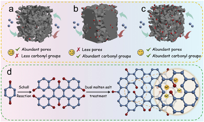
To date, there still exists a trade-off between porosity and carbonyl content in carbon nanomaterials, which are the two critical factors for improving both EDLC and pseudocapacitance of ZICs. Specifically, enhancing the porosity often results in a reduction of carbonyl functional groups (Fig. 1a), while maintaining a high carbonyl content hinders the development of a highly porous structure (Fig. 1b). Therefore, the design of carbon nanomaterials that simultaneously possess abundant porous structures and high carbonyl content is essential for achieving zinc-ion capacitors with both high-energy density and high-power density (Fig. 1c). In this work, a carbonyl-enriched porous carbon nanomaterial is developed through a combined strategy of Scholl coupling reaction and dual molten salt treatment, using p-benzoquinone as the building block. Structural analysis indicates that the use of zinc chloride molten salt promotes the formation of a rich microporous structure, while iron chloride molten salt facilitates the retention of high carbonyl content. Notably, the dual molten salt treatment yields a porous carbon material (CPC-FeZn) with optimized pore size distribution and the highest carbonyl content, which are demonstrated as the critical structural characters for the storage and transfer of Zn(H2O)62+ by the DFT calculations. The resultant CPC-FeZn exhibits exceptional ZICs performance, achieving a specific capacitance of 256.1 F/g at 0.1 A/g, retaining 66.7% capacitance at 20 A/g, and delivering an energy density of 91.1 Wh/kg with outstanding cycling stability over 5000 cycles. These advancements endow ZICs as a scalable, high-performance solution for sustainable energy storage, addressing global demands for efficient and environmentally benign technologies.
Figure 1
Figure 1.
Design principle for the structural parameters of carbonaceous electrode with both high pseudocapacitance and EDLC: (a) Abundant pores but less carbonyl groups. (b) Abundant carbonyl groups but less pores. (c) Both abundant pores and carbonyl groups. (d) Schematic illustration for the preparation of CPC-FeZn and the bonding type with Zn2+.
Preparation of poly(p-benzoquinone) precursor: A solution was prepared by dissolving 2.59 g of p-benzoquinone in 120 mL of nitrobenzene and mixing homogeneously at room temperature. Subsequently, 3.89 g of anhydrous iron chloride was added to the solution, and the mixture was heated in an oil bath at 120 ℃ with magnetic stirring for 24 h. After cooling to room temperature, the product was filtered under suction using a 1 mol/L hydrochloric acid solution and subjected to Soxhlet extraction for 24 h. The extracted material was dried overnight at 80 ℃ in an oven, ground into a uniform powder, and stored for further use.
Preparation of anhydrous iron chloride-treated porous carbon nanomaterial (CPC-Fe): A mixture of 500.00 mg of poly(p-benzoquinone) precursor and 2.5 g of anhydrous iron chloride was dissolved in 40.0 mL of anhydrous ethanol and ultrasonicated for 30 min to ensure uniform dispersion of the solid powder. The mixture was heated in an oil bath at 80 ℃ until the ethanol completely evaporated. The resulting mixture was transferred to a corundum boat and pretreated at 400 ℃ for 3 h under a nitrogen atmosphere with a heating rate of 5 ℃/min, followed by carbonization at 800 ℃ for 1 h. After cooling to room temperature, the carbonized sample was filtered under suction with a 1 mol/L hydrochloric acid solution and subjected to Soxhlet extraction to remove residual metal particles and impurities. The material was dried overnight at 80 ℃ in an oven and ground uniformly to obtain CPC-Fe.
Preparation of anhydrous zinc chloride-treated porous carbon nanomaterial (CPC-Zn): A mixture of 500.00 mg of poly(p-benzoquinone) precursor and 2.5 g of anhydrous zinc chloride was dissolved in 40.0 mL of anhydrous ethanol. The subsequent steps were identical to those used for CPC-Fe preparation, yielding CPC-Zn.
Preparation of dual anhydrous iron chloride and zinc chloride-treated porous carbon nanomaterial (CPC-FeZn): A mixture of 500.00 mg of poly(p-benzoquinone) precursor, 2.5 g of anhydrous iron chloride, and 2.5 g of anhydrous zinc chloride was dissolved in 40.0 mL of anhydrous ethanol. The subsequent steps were identical to those used for CPC-Fe preparation, yielding CPC-FeZn.
Preparation of porous carbon material without molten salt treatment (CPC): A sample of 500.00 mg of poly(p-benzoquinone) precursor was dissolved in 40.0 mL of anhydrous ethanol. The subsequent steps were identical to those used for CPC-Fe preparation, yielding CPC.
The preparation of the carbonyl-enriched porous carbon materials is illustrated in Fig. 1d. A carbonyl-enriched poly(p-benzoquinone) is first synthesized using p-benzoquinone as a precursor through the Scholl coupling reaction [25,26], which is followed by a molten salt-assisted pyrolysis. The choice of p-benzoquinone as the building block is due to its abundant carbonyl groups and rigid structure, which not only facilitates the inheritance of a high carbonyl content in the product but also promotes the extension of the π-conjugated structure. Given that iron chloride and zinc chloride can respectively preserve oxygen-containing functional groups and promote the formation of micropores [27,28], poly(p-benzoquinone) precursors are subjected to molten salt pyrolysis with either anhydrous iron chloride or anhydrous zinc chloride, yielding carbonyl-rich porous carbon materials (CPC-Fe and CPC-Zn, respectively). The abundant carbonyl groups in CPC-Fe are expected to enhance pseudocapacitance, while the micropore-enriched structure in CPC-Zn may facilitate high electric double-layer capacitance. Consequently, a dual molten salt treatment using both iron chloride and zinc chloride is employed to pursue a functional carbon nanomaterial (CPC-FeZn) with both abundant pore structures and high carbonyl group content. For comparison, a control sample is prepared via pyrolysis without molten salt treatment, named as CPC. The detailed synthetic process can be seen in the Materials synthesis methods (Supporting information).
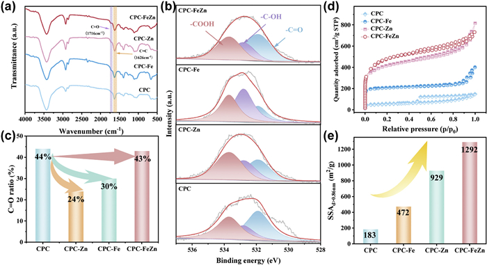
The chemical compositions of CPC, CPC-Fe, CPC-Zn, and CPC-FeZn are characterized using Fourier transform infrared (FT-IR) spectroscopy and X-ray photoelectron spectroscopy (XPS). The FT-IR spectra (Fig. 2a) exhibit a characteristic C═O absorption peak at 1716 cm−1 for all samples, confirming the successful incorporation of oxygen into their carbon frameworks [29]. XPS analysis is employed to investigate the elemental composition and chemical states of the samples. As shown in Fig. S1 and Table S1 (Supporting information), all materials mainly contain carbon and oxygen elements. High-resolution C 1s spectra are deconvoluted into four peaks: -C═C- (284.7 eV), -C-O- (285.3 eV), -C═O- (286.4 eV), and -COOH (289 eV) [30-32], further validating the integration of oxygen atoms into the carbon matrix (Fig. S2 in Supporting information). Similarly, high-resolution O 1s spectra display three peaks at 531.9, 532.8, and 533.7 eV, corresponding to -C═O, -C-OH, and -COOH groups [33], respectively (Fig. 2b). According to Table S1, the oxygen content of molten salt-treated samples increases compared to CPC (5.95 at%), with CPC-Zn exhibiting the highest oxygen content (10.19 at%), followed by CPC-Fe (8.47 at%) and CPC-FeZn (7.04 at%). In zinc-ion capacitors, the -C═O groups within oxygen-containing functional groups are the primary reactive sites during charge-discharge process, contributing additional capacitance through reversible Zn2+ adsorption/desorption [34,35]. Herein, analysis of the distribution of oxygen-containing functional groups (Fig. 2c) reveals that CPC-Fe holds a higher -C═O proportion (30%, 2.54 at%) compared to CPC-Zn (24%, 2.44 at%), likely due to molten iron chloride could better preserve the stability of the -C═O structure during pyrolysis. CPC-FeZn exhibits the highest -C═O proportion (43%) and content (3.01 at%), indicating that dual molten salt treatment with iron and zinc chloride optimizes the retention of reactive sites for superior electrochemical performance in ZICs.
Figure 2
Figure 2.
Analysis for the evolution of both the carbonyl group and porous structures within the samples: (a) FTIR spectra; (b) high-resolution O 1s XPS spectra; (c) comparison for the ratios of carbonyl group; (d) nitrogen adsorption-desorption isotherms; (e) comparison for the SSAd > 0.86nm.
To elucidate the evolution of oxygen content during carbonization, thermogravimetric analysis (TGA) is conducted. Poly-p-benzoquinone polymers are first mixed with the respective activating salts (ZnCl2, FeCl3, or ZnCl2+FeCl3) as specified in the Materials synthesis methods, and then subjected to TGA under the same condition to that of their fabrication process. The TGA curves (Fig. S3 in Supporting information) and differential thermalgravimetric analysis (DTG) curves (Fig. S4 in Supporting information) reveal distinct weight loss events for each treatment. For the three samples, the initial obvious loss at ∼95 ℃ is probably attributed to the evaporation of adsorbed moisture or low-boiling-point impurities. Specifically, for the CPC-Zn, the loss at 220 ℃, likely corresponds to the preliminary decomposition of polymer functional groups (e.g., carbonyl or hydroxyl groups), releasing volatile small molecules, or an initial surface reaction with solid ZnCl2. The significant loss at 550 ℃, above melting point (290 ℃) of ZnCl2 but below its boiling point (732 ℃), suggests ZnCl2 acts as an activating agent, promoting pore formation in the carbon material. This stage may involve further polymer decomposition and partial thermal degradation of carbonyl groups, contributing to the lowest carbonyl content observed in CPC-Zn. For the CPC-Fe, the 160 ℃ loss, occurring well below the melting point of FeCl3 (305 ℃) and boiling point (316 ℃), may result from early decomposition of polymer functional groups or an initial reaction with solid FeCl3. The high-temperature loss at 740 ℃, significantly exceeding the boiling point of FeCl3, indicates that FeCl3 volatilization is delayed due to interactions with the polymer matrix, possibly occurring partially during the retention at 400 ℃. This late-stage weight loss suggests FeCl3 stabilizes carbonyl groups at elevated temperatures, reducing their decomposition and resulting in a higher carbonyl content in CPC-Fe compared to CPC-Zn. For the CPC-FeZn, the 210 ℃ loss, below the melting points of both salts, likely corresponds to polymer functional group decomposition or a synergistic initial reaction with ZnCl2 and FeCl3. The 545 ℃ loss, within the range where ZnCl2 is molten, is primarily associated with ZnCl2-driven activation, facilitating porous structure development alongside partial decomposition. The 700 ℃ loss, approaching the delayed volatilization temperature of FeCl3, again suggests its role in stabilizing carbonyl groups. The combined effects of pore-forming activation for ZnCl2 and carbonyl retention for FeCl3 yield the highest carbonyl content in CPC-FeZn. In summary, the TGA/DTG results highlight distinct roles of the molten salts: ZnCl2 promotes porosity but leads to carbonyl loss at 550 ℃ in CPC-Zn; FeCl3 stabilizes carbonyl groups at 740 ℃ in CPC-Fe; and the ZnCl2- FeCl3 synergy in CPC-FeZn optimizes both porosity (545 ℃) and carbonyl retention (700 ℃), aligning with the observed carbonyl content trend from the XPS analysis results.
The influence of molten salt treatment on the pore structure of the materials is investigated through nitrogen adsorption/desorption measurement. As shown in Fig. 2d, the nitrogen adsorption/desorption isotherms of CPC-Fe, CPC-Zn, and CPC-FeZn exhibit typical Type Ⅳ behavior, while CPC displays a characteristic Type Ⅰ isotherm [34,36]. The SSA of CPC is 195.1 m2/g, whereas molten salt-treated samples show significant variations (Table S2 in Supporting information): CPC-Zn and CPC-FeZn have comparable SSAs of 1498.6 and 1677.6 m2/g, respectively, while CPC-Fe shows an SSA of 814.5 m2/g. This difference may be attributed to anhydrous zinc chloride facilitating the formation of abundant micropores and mesopores during molten salt pyrolysis, as evidenced by the PSD analysis (Fig. S5 in Supporting information). Further examination of the PSD reveals that, compared to CPC, which contains only trace amounts of micro- and mesopores, CPC-Fe, CPC-Zn, and CPC-FeZn possess significantly richer micro- and mesoporous structures. Based on these characterizations, it can be inferred that anhydrous zinc chloride promotes the formation of defects and pores in carbon nanomaterials during molten salt pyrolysis, while anhydrous iron chloride contributes to defect repair, consistent with our previous report [37].
It is worth mentioning that the solvated [Zn(H2O)6]2+ is considered the primary charge carrier in zinc-ion capacitors during charging and discharging, with a large ionic diameter of 0.86 nm [38,39]. The substantial size of [Zn(H2O)6]2+ implies that it cannot penetrate the interior of carbon materials with excessive submicropores [40], leading to significantly reduced space utilization and active site accessibility, thereby diminishing Zn2+ storage capacitance. Consequently, appropriate pore sizes are essential to unlock the full potential of carbon materials [41,42]. By comparing the volume ratios and SSA of pores with size larger than 0.86 nm (V> 0.86nm/Vtotal and SSAd > 0.86nm) across different samples (Table S2 and Fig. 2e), it is observed that although CPC exhibits the highest V> 0.86nm/Vtotal ratio (94%), its total pore volume Vtotal and SSAd > 0.86nm are substantially lower compared to CPC-Fe, CPC-Zn, and CPC-FeZn. Moreover, the V> 0.86nm/Vtotal ratio and SSAd > 0.86nm of CPC-Zn (62% and 929 m2/g) are also higher than that of CPC-Fe (58% and 472 m2/g), suggesting that anhydrous zinc chloride treatment during molten salt pyrolysis promotes the formation of more pores and defects in carbon materials while creating a greater number of suitable pore sizes. Interestingly, CPC-FeZn exhibits similar Vtotal and V> 0.86nm/Vtotal ratios to CPC-Zn, yet the SSAd > 0.86nm value (1292 m2/g) of CPC-FeZn is the largest, indicating that dual molten salt treatment enables CPC-FeZn to possess a large specific surface area, abundant defects, and well-matched ion transport pore sizes.
The morphological and microstructural characteristics of CPC, CPC-Fe, CPC-Zn, and CPC-FeZn are investigated using scanning electron microscopy (SEM) and transmission electron microscopy (TEM). CPC, which is not subjected to molten salt treatment, exhibits a block-like structure (Fig. S6a in Supporting information) with numerous amorphous regions (Fig. S6b in Supporting information). In comparison, CPC-Fe, treated with iron chloride, exhibits a morphology characterized by particle accumulation (Fig. S7a in Supporting information). Further TEM analysis reveals the presence of graphite microcrystalline structures (Fig. S7b in Supporting information). In contrast, CPC-Zn, treated with zinc chloride, displays a similar particle accumulation morphology (Figure S8a in Supporting information), with TEM analysis indicating morphological features that include a few distinct turbo-like carbon structures (Fig. S8b in Supporting information). CPC-FeZn, derived from the poly(p-benzoquinone) precursor treated with a combination of iron and zinc chloride molten salts, demonstrates a similar particle accumulation morphology (Fig. S9a in Supporting information) to that of CPC-Fe and CPC-Zn, while TEM analysis confirms the presence of a typical turbo-like carbon structure (Fig. S9b in Supporting information). Furthermore, selected area electron diffraction (SAED) analysis is performed on CPC-Fe, CPC-Zn, and CPC-FeZn. All three materials exhibit an amorphous structure (Fig. S10 in Supporting information), consistent with the findings from SEM and TEM analyses. Additionally, high-angle annular dark-field scanning transmission electron microscopy (HAADF-STEM), coupled with energy-dispersive X-ray spectroscopy (EDS), is utilized to confirm a uniform distribution of oxygen within the carbon framework for CPC-FeZn (Fig. S11 in Supporting information).
The defect structures of the samples are characterized using X-ray diffraction (XRD) and Raman spectroscopy. CPC exhibits characteristic peaks at 25.8° and 42.9° (Fig. S12 in Supporting information), corresponding to the (002) and (100) planes of graphite, respectively [43,44]. The narrow peak at 25.8° indicates a high degree of graphitization in the CPC carbon framework. In contrast, the characteristic peaks of CPC-Fe, CPC-Zn, and CPC-FeZn, which are treated by molten salt, show broader shape at these positions, suggesting the formation of amorphous structures in the carbon framework, consistent with TEM and SAED analysis. Additionally, the peak at 25.8° shifts to a lower angle, indicating an increased interlayer spacing in the molten salt-treated samples. Further quantitative analysis of defect density is performed using Raman spectroscopy. The Raman spectra of all samples are deconvoluted via Gaussian fitting into five peaks within the 1000–1750 cm−1 range: D2 (1250 cm−1), D (1352 cm−1), D1 (1468 cm−1), G (1582 cm−1), and D’ (1625 cm−1). The D peak reflects defects and disorder in the material, representing sp3-type disordered carbon, while the G peak corresponds to lattice vibrations and order, indicative of sp2-type graphitic carbon [45]. The intensity ratio of the D peak to the G peak (ID/IG) is commonly used to quantify defect density. Calculations reveal an ID/IG value of 1.07 for CPC (Figs. S13 and S14a in Supporting information), whereas the molten salt-treated samples exhibit higher ID/IG values: CPC-Zn has the highest ID/IG value of 1.14 (Fig. S14b in Supporting information), followed by CPC-FeZn at 1.12 (Fig. S14c in Supporting information), and CPC-Fe at 1.09 (Fig. S14d in Supporting information). These results indicate that anhydrous zinc chloride treatment effectively increases the defect density in the samples.
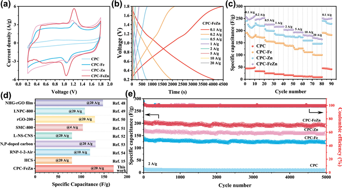
Given that CPC-FeZn possesses a high specific surface area, appropriate pore size distribution and a high content of -C═O groups, it is promising to exhibit excellent performance in ZICs. At first, the electrochemical behavior of CPC, CPC-Fe, CPC-Zn, and CPC-FeZn as cathode materials for aqueous ZICs is investigated using cyclic voltammetry (CV) and galvanostatic charge-discharge (GCD) tests. Comparing the CV curves of ZICs assembled with different materials, CPC exhibits significant polarization at higher potentials, whereas CPC-Fe, CPC-Zn, and CPC-FeZn display quasi-rectangular CV curves (Fig. 3a), indicating the typical EDLC behavior. Surprisingly, a pair of redox peaks are present in the CV curves, probably resulting from reversible redox reactions during zinc deposition/stripping, which further enhances the capacitance for zinc-ion storage. An intensive comparison of the CV curves reveals that CPC-Fe, CPC-Zn, and CPC-FeZn exhibit a pair of redox peaks at ∼1.05 V/1.22 V, with CPC-FeZn showing more distinct oxidation/reduction peaks compared to CPC-Fe and CPC-Zn. This may be attributed to reversible chemical adsorption of Zn2+ by carbonyl group during the charge/discharge processes, generating significant pseudocapacitance [46,47]. The less prominent redox peaks in the CV curve for CPC are likely due to its lower content of C═O group, failing to provide sufficient chemical adsorption sites. Furthermore, the area of the CV curve of the CPC-FeZn cathode is the largest, demonstrating that the CPC-FeZn cathode provides the greatest reversible capacitance.
Figure 3
Figure 3.
Electrochemical performance of the samples. (a) CV curves at 20 mV/s scan rate. (b) GCD curves of CPC-FeZn at different current densities from 0.1 A/g to 20 A/g. (c) Rate capabilities tested at different current densities. (d) Comparison of the specific capacitance at high current density between CPC-FeZn and other carbonaceous materials from the recent literatures. (e) Long cycling performance tested at 2 A/g for 5, 000 cycles.
Subsequent analysis of the GCD curves of the zinc-ion capacitors (Fig. 3b and Figs. S15-S17 in Supporting information) shows that the capacitance of the CPC cathode is negligible compared to those of CPC-Fe, CPC-Zn, and CPC-FeZn. The CPC-FeZn cathode exhibits the highest specific capacitance of 256.1 F/g at 0.1 A/g and maintains a high capacitance of 170.7 F/g even at 20 A/g. To more clearly observe the differences in electrochemical performance among these materials, the GCD curves at a current density of 1 A/g are compared (Fig. S18 in Supporting information). The results indicate significant variations among the cathode materials, with CPC-FeZn showing the highest capacitance of 215.6 F/g, followed by CPC-Zn (187.5 F/g), CPC-Fe (152.6 F/g), and CPC (21.2 F/g). Additionally, the rate capability of the materials is investigated, revealing that CPC-FeZn demonstrates excellent rate capability at higher current densities (Fig. 3c). Even at an ultra-high current density of 20 A/g, CPC-FeZn provides a reversible capacitance of 170.7 F/g, with a capacitance retention rate of 66.7%. In comparison, the capacitance retention rates at 20 A/g for CPC, CPC-Fe, and CPC-Zn are 19.5%, 52.9%, and 60.7%, respectively. The rate performance of the molten salt-treated cathode materials significantly surpasses that of CPC, possibly due to its smaller specific surface area and lack of abundant pores, which hinder rapid ion diffusion. Moreover, when the current density is restored to 0.1 A/g, the capacitance of CPC-FeZn recovers to 250.0 F/g, further confirming its excellent rate performance and reversible Zn2+ storage. It is noteworthy that the rate capability performance of CPC-FeZn has achieved an outstanding level, particularly with its specific capacitance at high current densities significantly surpassing that reported in recent literatures (Fig. 3d) [15,48-54]. The ZICs based on the CPC-FeZn cathode also exhibit outstanding cycling stability, maintaining a capacitance retention rate of 94% after 5000 cycles at 2 A/g (Fig. 3e). Ragone plots (Fig. S19 in Supporting information) indicate that CPC-FeZn delivers a high energy density of 91.1 Wh/kg at a power density of 80 W/kg, surpassing that of CPC (15.9 Wh/kg), CPC-Fe (68 Wh/kg), and CPC-Zn (85.5 Wh/kg). Compared to other works, the ZIC based on the CPC-FeZn cathode demonstrates significant advantages in terms of specific capacitance, power density, and energy density (Table S3 in Supporting information), underscoring the great potential of the dual molten salt pyrolysis strategy based on the carbonyl-enriched carbonaceous electrode in promoting Zn2+ transport and storage.
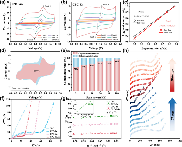
To explore the electrochemical behavior and charge storage contributions of the assembled ZICs, CV curves at different scan rates ranging from 2 mV/s to 100 mV/s are further examined (Figs. 4a and b, Figs. S20 and S21 in Supporting information). The CV curves of the ZICs based on the CPC-FeZn cathode exhibit typical redox peaks, indicating that the charge storage process involves a synergistic effect of pseudocapacitance and EDLC. The relationship between the peak current (i) of the oxidation and reduction peaks and the scan rate (ν) can be described by the following equation:
i=aνb
(1)
where a and b are variable parameters. Typically, a b value close to 0.5 suggests slow reaction kinetics, while a b value close to 1.0 indicates fast reaction kinetics dominated by capacitive behavior [55]. By plotting log(i) against ν, the b value can be obtained from the slope (Fig. 4c and Figs. S22-S24 in Supporting information). Calculations based on Eq. 1 show that the b values for both the reduction and oxidation peaks of all the cathode materials are close to 1.0, suggesting that the charge storage mechanism in aqueous ZICs is primarily governed by fast reaction kinetics controlled by capacitive behavior.
Figure 4
Figure 4.
Kinetic analysis of the ZICs cathodes based on the samples in this work. CV curves at scan rate range of 2–100 mV/s for (a) CPC-FeZn and (b) CPC-Zn. (c) Linear relationship between logarithmic currents and logarithmic sweep rate and the calculated b values for CPC-FeZn. (d) The capacitive and diffusion contribution from the CV curve at a scan rate of 20 mV/s for CPC-FeZn. (e) The capacitive and diffusion contribution at different scan rates from 2 mV/s to 100 mV/s for CPC-FeZn. (f) Nyquist plots and (g) linear plots of real impedances (Z’) against angular frequencies (ω−1/2) for all the samples. (h) In-situ EIS plots for the ZICs based on CPC-FeZn.
Further analysis using the Dunn method [56] is conducted to quantify the contributions of fast and sluggish reaction kinetics. The relationship between the peak current (i) and the scan rate (ν) can be expressed as follows:
i=k1ν+k2ν1/2
(2)
where k1 and k2 are constants, and k1ν represents the current contribution from the capacitance-controlled fast reaction kinetics, with i being the total current. According to Eq. 2, by plotting i/ν1/2 against ν1/2, the k1 can be obtained from the slope. Using the CV curve at a scan rate of 20 mV/s (Fig. 4d and Figs. S25-S27 in Supporting information) as a reference, the area enclosed by k1ν (red region) is calculated, representing the proportion of capacitance-dominated fast reaction kinetics during the charge/discharge process for CPC, CPC-Fe, CPC-Zn, and CPC-FeZn cathodes, which are 49.9%, 69.8%, 80.2%, and 89.0%, respectively. Additionally, as the scan rate increases, the contribution of fast reaction kinetics also shows an upward trend (Figs. S28-S30 in Supporting information), with the CPC-FeZn cathode increasing from 72% to 95% (Fig. 4e), indicating that the CPC-FeZn cathode exhibits the highest contribution through fast reaction kinetics.
Subsequently, electrochemical impedance spectroscopy (EIS) tests are performed to investigate the effect of all the cathodes on enhancing charge transfer kinetics. The diameter of the semicircle in the high-frequency region is positively correlated with the charge transfer resistance (Rct), while the slope in the low-frequency region is negatively correlated with the ion diffusion resistance (σ) in the electrolyte [57]. From the Nyquist plot (Fig. 4f), it is evident that the Rct of CPC is significantly higher than that of CPC-Fe, CPC-Zn, and CPC-FeZn, suggesting that the molten salt-treated cathode materials can substantially improve the charge transfer rate. Among these materials, the Rct of CPC-FeZn is the smallest, which may be attributed to its abundant oxygen-containing functional groups, larger specific surface area, higher defect density, and more suitable pore sizes, facilitating electrolyte penetration and thereby accelerating ion transport. Additionally, the value of σ can be determined by fitting the relationship between the real part of the impedance (Z’) and the angular frequency (ω), as expressed by the following equation [52]:
Zw=σω−1/2−jσω−1/2
(3)
where σω−1/2 is the real part of the impedance (Z’), − jσω−1/2 is the imaginary part (Z’’), and σ is the ion diffusion resistance. By plotting Z’ against ω−1/2, the slope obtained is equal to the σ value (Fig. 4g). Among the samples, CPC-FeZn shows the smallest σ value of 8.64 Ω s−1/2, followed by CPC-Zn (13.27 Ω s−1/2), CPC-Fe (21.76 Ω s−1/2), and CPC (951.74 Ω s−1/2), further demonstrating that CPC-FeZn enhances Zn2+ diffusion behavior and exhibits superior ion diffusion kinetics. In addition, in-situ EIS is employed during the charge-discharge process to study the kinetic behavior of the CPC-FeZn-based ZICs (Fig. 4h). During the discharge process, the Rct value gradually increases along with the voltage is reduced, which is ascribed to the formation of the by-products at the electrolyte-CPC-FeZn interface. Conversely, the Rct value could be reduced and even be restored to the initial state after the ZICs is charged to 1.8 V, highlighting the excellent charge transfer capability of CPC-FeZn as the cathode for ZICs.
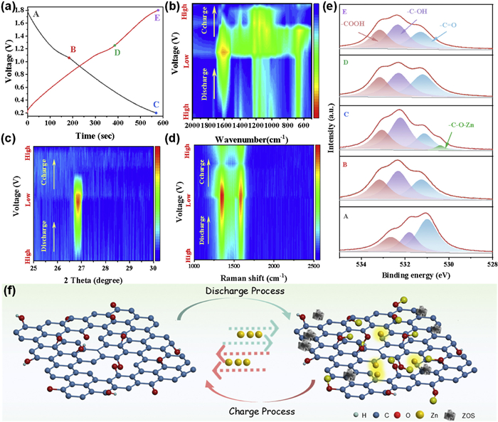
The charge storage mechanism of the CPC-FeZn cathode during the charge/discharge process is analyzed through a series of ex-situ characterization techniques, including FT-IR, XRD, Raman and XPS. Five distinct states (Fig. 5a) during a complete charge-discharge cycle are selected for investigation: States A to C correspond to the discharge process, and states C to E correspond to the charge process. Ex-situ FT-IR spectra (Fig. 5b) reveal that the -C═O peak intensity at 1700 cm−1 gradually weakens from state A to state C and then progressively recovers to its initial intensity from state C to state E, indicating that -C═O participates in the charge-discharge process, enhancing the capacitance of CPC-FeZn through redox reactions. Additionally, ex-situ XRD (Fig. 5c) shows that the (002) peak (∼26.8°) exists throughout the charge-discharge process, with its intensity increasing during discharge and decreasing during charging, possibly due to the reversible involvement of electrolyte ions in the charge/discharge process [58,59]. The evolution of graphitization degree of CPC-FeZn during charge/discharge is further characterized using ex-situ Raman spectroscopy (Fig. 5d). During the discharge process, an enhanced defect density can be observed in the CPC-FeZn cathode, and the highest intensity is attained when it is fully discharged at 0.2 V, which is due to the Zn2+ adsorption on the defective sites. On the contrary, the intensities of the D peak and G peak gradually decrease along with the applied potential enhances to 1.8 V, further confirming the reversible adsorption/desorption of electrolyte ions, which is consistent with the ex-situ XRD results [60]. Moreover, the interaction between the active sites and Zn2+ is further disclosed via the ex-situ O 1s XPS spectra (Fig. 5e). The presence of -C═O, -C-OH, and -COOH could be observed in all the five states. During the discharge process (state A to state C), the -C═O peak intensity decreases, while a characteristic -C-O-Zn absorption peak appears at state C (fully discharged state), indicating that -C═O contributes to the specific capacitance through interaction with Zn2+ during discharge. In the corresponding charging process (state C to state E), the peak intensity of -C═O nearly recovers to its initial state (state A), while the -C-OH peak intensity decreases, and the -C-O-Zn peak disappears, suggesting that C═O bond plays a key role in improving the specific capacitance of the cathode via a reversible redox reaction: -C═O + Zn2+ + e− ↔ -C-O-Zn [61], which is consistent with the ex-situ FT-IR results.
Figure 5
Figure 5.
Investigation for the charge storage mechanism of the samples. (a) Typical GCD curve of CPC-FeZn and five (A, B, C, D and E) selected states at different charge/discharge processes. (b) Ex-situ FT-IR spectra; (c) ex-situ XRD pattern; (d) ex-situ Raman spectra and (e) ex-situ O 1s XPS spectra corresponding to the five states in (a). (f) Proposed charge storage mechanism of CPC-FeZn in ZICs.
In summary, the charge-discharge mechanism of CPC-FeZn can be explained by the following process (Fig. 5f): During the discharge process, carbonyl groups strongly interact chemically with Zn2+, while carbon defect structures adsorb Zn2+ electrostatically, accompanied by the formation of by-products at the interface between the electrolyte and the electrode material. During the charge process, the reversible nature of these chemical and electrostatic interactions enables the electrode material to revert to its initial state, thereby ensuring excellent reversibility throughout the charge-discharge process.
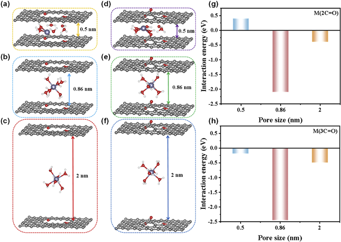
The impact of pore size on the interaction strength with Zn2+ is further examined by density functional theory (DFT) simulations. A carbonyl-doped bilayer carbon framework is selected as the slit pore model to examine the energy variation trend in the interaction between Zn(H2O)62+ and models with different pore sizes. The interaction energy between the model and Zn(H2O)62+ is adopted as the parameter indicator, where a more negative interaction energy signifies a stronger interaction between the model and Zn(H2O)62+. Comparing models M(2C═O)-0.5, M(2C═O)-0.86, M(2C═O)-2, which possess identical carbonyl content but different pore sizes, it is observed that at a pore size of 0.5 nm, the interaction energy reaches a high value of 0.40 eV (Fig. 6a), indicating that Zn(H2O)62+ can hardly pass through this slit model. When the pore size increases to 0.86 nm (Fig. 6b), the interaction energy decreases to its lowest value of −2.09 eV, primarily due to the suitable match between this pore size and the ionic size of Zn(H2O)62+. However, as the pore size further increases to 2 nm (Fig. 6c), the interaction energy rises again to −0.39 eV, suggesting that further enlargement of the pore size weakens the interaction between the material surface and Zn(H2O)62+. Based on these models, it is reasonable that despite having similar carbonyl content, CPC-Fe and CPC-Zn exhibit different zinc ion storage performances, with the latter possessing a greater proportion of pores larger than 0.86 nm, thereby demonstrating superior zinc ion storage capability.
Figure 6
Figure 6.
Theoretical analysis for the pore sizes and C═O bonds. Diffusion behaviors of Zn(H2O)62+ ions within pore sizes of (a) M(2C═O)-0.5: 0.5 nm; (b) M(2C═O)-0.86: 0.86 nm; (c) M(2C═O)-2: 2.0 nm; (d) M(3C═O)-0.5; (e) M(3C═O)-0.86; (f) M(3C═O)-2: diffusion behaviors of Zn(H2O)62+ ions within higher carbonyl content but same pore size of (a)-(c). Comparison of the interaction energy values for (g) M(2C═O) models and (h) M(3C═O) models.
Subsequently, models M(3C═O)-0.5, M(3C═O)-0.86, M(3C═O)-2 are constructed (Figs. 6d–f) to further explore the effect of carbonyl content on the interaction energy between the model and Zn(H2O)62+. These models share the same interlayer spacing as models M(2C═O)-0.5, M(2C═O)-0.86, M(2C═O)-2 but hold higher carbonyl content. Interestingly, the model (M(3C═O)) with different pore sizes but the same carbonyl content exhibit the same trend with that of the M(2C═O) model (Figs. 6g and h), consolidating the above conclusion that the pore size of 0.86 nm is the most suitable size for the storage and transfer of Zn(H2O)62+. Comparing models M(2C═O)-0.5 with M(3C═O)-0.5 (Fig. 6d), M(2C═O)-0.86 with M(3C═O)-0.86 (Fig. 6e), and M(2C═O)-2 with M(3C═O)-2 (Fig. 6f), it is observed that, for the same pore size, an increase in carbonyl content reduces the interaction energy between Zn(H2O)62+ and the slit model (Figs. S31-S33 in Supporting information). This reduction enhances the kinetic diffusion and adsorption processes of Zn(H2O)62+ during electrochemical charge-discharge process. These observations theoretically elucidate the above experimental results: Although having similar pore structures, CPC-Zn and CPC-FeZn exhibit different zinc ion storage performances, with the latter benefiting from higher carbonyl content and thus superior zinc ion storage capability.
In this work, the Scholl coupling reaction with a molten salt-assisted pyrolysis strategy is successfully coupled to synthesize a series of carbonyl-enriched porous carbon nanomaterials. By precisely controlling the molten salt treatment process, we demonstrate the pore structures and carbonyl active sites can be synergistically modulated. Structural characterization and electrochemical analysis elucidate the relationship between critical structure parameters and electrochemical performance: Anhydrous zinc chloride enhances the specific surface area and provides suitable pore sizes, thereby facilitating a larger electric double-layer capacitance in zinc-ion capacitors; while anhydrous iron chloride maintains the proportion of carbonyl active sites, establishing a structural foundation for greater pseudocapacitance. The optimized CPC-FeZn cathode material, constructed by the dual molten salt treatment, exhibits the highest SSAd > 0.86 nm (1292 m2/g) and carbonyl content (3.01 at%), demonstrating a Zn2+ storage mechanism that couples electric double-layer capacitance with reversible redox reactions in zinc-ion capacitors. Furthermore, the CPC-FeZn cathode showcases outstanding zinc ion storage capabilities, including a reversible capacitance of 256.1 F/g at 0.1 A/g, excellent rate performance at a high current density of 20 A/g (170.7 F/g), ideal cycling stability (94% capacitance retention after 5000 cycles at 2 A/g) and a high energy density of 91.1 Wh/kg at a power density of 80 W/kg. Considering the synthesis process for CPC-FeZn is straightforward, involving mild reaction conditions, and the molten salts are relatively low-cost, this approach holds strong potential for facile large-scale production. In addition, this work provides a material design paradigm for developing carbon-based cathode materials for high-performance zinc-ion capacitors that integrate electric double-layer capacitance and pseudocapacitance.
CRediT authorship contribution statement
Jiale Zhang: Software, Methodology, Investigation, Data curation. Ruifang Zhang: Writing – original draft, Investigation, Formal analysis. Shuaihua Zhang: Validation, Formal analysis, Data curation. Runze Gao: Visualization, Software, Methodology, Data curation. Qi Yang: Writing – original draft, Resources, Investigation, Conceptualization. Debin Kong: Writing – original draft, Conceptualization. Bin Luo: Writing – review & editing. Zhichang Xiao: Writing – review & editing, Supervision, Resources, Conceptualization.
Declaration of competing interest
The authors declare that they have no known competing financial interests or personal relationships that could have appeared to influence the work reported in this paper.
Acknowledgments
The authors acknowledge the financial support from the National Natural Science Foundation of China (Nos. 52302335, U20A20131 and 22005084), the supporting funds by Civil Aviation University of China (No. 3122024PT21), the Science Research Project of Hebei Education Department (No. BJK2023021), and the Basic Research Project of Shijiazhuang Municipal Universities in Hebei Province (No. 241790647A). The authors acknowledge the language refinement and grammatical verification provided by AI-assisted editing tools, including Grammarly and ChatGPT, during the manuscript preparation process.
Supplementary materials
Supplementary material associated with this article can be found, in the online version, at doi:10.1016/j.cclet.2025.111867.
H.X. Li, W.J. Shi, L.Y. Liu, et al., Chem. Eng. J. 487 (2024) 150630. doi: 10.1016/j.cej.2024.150630
[59]
P. Liu, W. Liu, Y. Huang, et al., Energy Storage Mater. 25 (2020) 858–865. doi: 10.1016/j.ensm.2019.09.004
[60]
X. Li, Y. Li, X. Zhao, et al., Energy Storage Mater. 53 (2022) 505–513. doi: 10.3390/mi13040505
[61]
C. Zhao, Y. Lin, Q. Lin, et al., Energy Storage Mater. 58 (2023) 332–343. doi: 10.1016/j.ensm.2023.03.039
Figure 1
Design principle for the structural parameters of carbonaceous electrode with both high pseudocapacitance and EDLC: (a) Abundant pores but less carbonyl groups. (b) Abundant carbonyl groups but less pores. (c) Both abundant pores and carbonyl groups. (d) Schematic illustration for the preparation of CPC-FeZn and the bonding type with Zn2+.
Figure 2
Analysis for the evolution of both the carbonyl group and porous structures within the samples: (a) FTIR spectra; (b) high-resolution O 1s XPS spectra; (c) comparison for the ratios of carbonyl group; (d) nitrogen adsorption-desorption isotherms; (e) comparison for the SSAd > 0.86nm.
Figure 3
Electrochemical performance of the samples. (a) CV curves at 20 mV/s scan rate. (b) GCD curves of CPC-FeZn at different current densities from 0.1 A/g to 20 A/g. (c) Rate capabilities tested at different current densities. (d) Comparison of the specific capacitance at high current density between CPC-FeZn and other carbonaceous materials from the recent literatures. (e) Long cycling performance tested at 2 A/g for 5, 000 cycles.
Figure 4
Kinetic analysis of the ZICs cathodes based on the samples in this work. CV curves at scan rate range of 2–100 mV/s for (a) CPC-FeZn and (b) CPC-Zn. (c) Linear relationship between logarithmic currents and logarithmic sweep rate and the calculated b values for CPC-FeZn. (d) The capacitive and diffusion contribution from the CV curve at a scan rate of 20 mV/s for CPC-FeZn. (e) The capacitive and diffusion contribution at different scan rates from 2 mV/s to 100 mV/s for CPC-FeZn. (f) Nyquist plots and (g) linear plots of real impedances (Z’) against angular frequencies (ω−1/2) for all the samples. (h) In-situ EIS plots for the ZICs based on CPC-FeZn.
Figure 5
Investigation for the charge storage mechanism of the samples. (a) Typical GCD curve of CPC-FeZn and five (A, B, C, D and E) selected states at different charge/discharge processes. (b) Ex-situ FT-IR spectra; (c) ex-situ XRD pattern; (d) ex-situ Raman spectra and (e) ex-situ O 1s XPS spectra corresponding to the five states in (a). (f) Proposed charge storage mechanism of CPC-FeZn in ZICs.
Figure 6
Theoretical analysis for the pore sizes and C═O bonds. Diffusion behaviors of Zn(H2O)62+ ions within pore sizes of (a) M(2C═O)-0.5: 0.5 nm; (b) M(2C═O)-0.86: 0.86 nm; (c) M(2C═O)-2: 2.0 nm; (d) M(3C═O)-0.5; (e) M(3C═O)-0.86; (f) M(3C═O)-2: diffusion behaviors of Zn(H2O)62+ ions within higher carbonyl content but same pore size of (a)-(c). Comparison of the interaction energy values for (g) M(2C═O) models and (h) M(3C═O) models.


 DownLoad:

 下载:


 下载:

