Received Date:
23 November 2024 Accepted Date:
21 September 2025 Revised Date:
15 September 2025 Available Online:
15 August 2026
Abstract:
Aqueous Zn//MnO2 batteries with Mn2+/MnO2 conversion reactions are highly promising due to their high redox potential and low cost. Typically, the conversion of Mn2+/MnO2 occurs at a strong acidic environment to ensure sufficient proton participation in the reaction, which will lead to Zn anode corrosion and electrolyte decomposition. Here, an acid-free mild electrolyte with Al2(SO4)3 as the additive to trigger Mn2+/MnO2 conversion through the hydrolysis of Al3+. This approach not only provides protons to enhance the two-electron transfer reaction but also utilizes the electrostatic shielding effect of Al3+ effectively inhibiting the formation of Zn dendrites and protecting the Zn anode. As a result, the assembled aqueous Zn//MnO2 battery exhibits high discharge voltage (1.6 V), long cycling stability (1900 cycles without decay) and excellent rate performance. Meanwhile, the anode-friendly electrolyte facilitates stable Zn plating/stripping and high Coulombic efficiency. This work proposes an effective strategy for enabling the two-electron process of MnO2 in mild aqueous Zn batteries.
The increasing reliance of human society on fossil fuels has led to severe global environmental challenges [1,2]. There is a pressing need to explore new energy storage solutions. Aqueous zinc-ion batteries (AZIBs) are promising candidates for future energy storage systems and are anticipated to become strong alternatives to lithium-ion batteries, owing to their enhanced safety characteristics and high energy density [3–7]. Among them, AZIBs have attracted intensity attentions due to the inherently high theoretical capacity of Zn (820 mAh/g) and non-toxicity [8–12]. The manganese oxides as the cathode materials received significant interest due to their low cost, high discharge potentials, and satisfactory rate and cycle performance [13–16]. MnO2 stands out as a cost-effective option, given the abundance and affordability of manganese, which helps reduce production expenses [17,18]. Its high discharge potential significantly boosts the energy density of AZIBs, allowing for greater energy density. As a non-toxic material, it meets the growing demand for sustainable energy storage solutions [19,20].
However, the reaction mechanism of the Mn-based AZIBs remains controversial. Three kinds of charge storage mechanisms have been reported so far: (1) The reversible Zn2+ intercalation/deintercalation in/from Mn-based cathode [21,22], (2) the reversible proton reaction accompanied by deposition of zinc hydroxide sulfate species [23,24] and (3) the successive intercalation/deintercalation of both H+ and Zn2+ at different charge/discharge stages [25–27], whatever the case, these mechanisms are usually related to one-electron transfer of Mn4+/Mn3+ with the capacity at about 300 mAh/g, which limits both capacities and output voltages [28]. The multivalent nature of Mn (+2, +3 and +4) offers potential for a two-electron Mn4+/Mn2+ reaction with a theoretical capacity of 616 mAh/g and a high theoretical voltage [29–33]. Despite efforts to enhance the MnO2/Mn2+ reaction, a high proton concentration is required to maintain the high redox voltage governed by the Nernst equation where protons are reactants. This two-electron transfer typically occurs in strongly acidic electrolytes, which facilitates the dissolution of MnO2 from the electrode [34,35]. However, such strong acidity poses several challenges. For one, it can lead to the corrosion of the zinc metal anode, compromising the overall integrity and lifespan of the battery [36–39]. For another, this acidic environment can promote hydrogen evolution, which not only decreases the efficiency of the battery but also contributes to gas bubble formation that can disrupt operation. Moreover, the issue of poor reversibility persists due to incomplete dissolution of MnO2 from the electrode surface during cycling [40,41]. This incomplete dissolution can hinder the effectiveness of the charge-discharge process, resulting in diminished capacity and performance over time. Addressing these challenges is essential for optimizing the use of MnO2 in aqueous zinc-ion batteries and ensuring their long-term viability as an energy storage solution. Therefore, developing a mild electrolyte that promotes MnO2 dissolution from the electrode while protecting the Zn metal anode from parasitic reactions is crucial for enhancing Mn-based AZIBs.
Herein, Al2(SO4)3 was introduced into the electrolyte as the additive to realize the two-electron reaction of Mn2+/MnO2 deposition/dissolution. Al3+ undergoes hydrolysis to supply necessary protons to promote MnO2 dissolution and increasing electrode potential according to Nernst’s equation. Besides, Al3+ can form an electrostatic shielding layer on the Zn surface, thus preventing the formation of Zn dendrite and ensuring long stability by inhibiting parasitic reactions. As a result, the Zn//MnO2 battery can achieve a high reversible redox reaction (1.6 V vs. Zn/Zn2+). The mild anode-friendly electrolyte enables outstanding stability and high plating/stripping Columbic efficiency of Zn anode. The Zn//MnO2 full battery demonstrates long cycling stability of 1900 cycles without capacity decay. This work holds promise for significantly enhancing the electrochemical performances of Zn//MnO2 batteries.
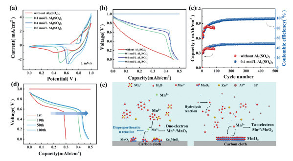
In three-electrode configuration, a pretreated carbon cloth served as the working electrode, a platinum plate as the counter electrode, saturated calomel electrode (SCE) as the reference electrode and 0.1 mol/L MnSO4 + 0.4 mol/L ZnSO4 solution with different concentration of Al2(SO4)3 additives as the electrolyte to explore its effects on the redox process. The mechanism of deposition/dissolution is that Mn2+ are oxidized during the charging process and then deposited on the carbon cloth electrode to form a solid MnO2 layer. In the following discharge phase, these MnO2 redissolve back into the electrolyte, promoting the reversibility of the reaction [42]. This behavior is illustrated by the cyclic voltammetry (CV) curves shown in Fig. 1a, which shows a distinct single-reduction peak at 0.6 V when Al3+ are present in the system. In contrast, in the absence of Al3+, a lower reduction peak was observed, which is consistent with previously reported data on a one electron transfer mechanism associated with the MnO2 cathode [43]. The difference suggests that the presence of Al3+ significantly affects electrochemical behavior. These results are further confirmed by the constant voltage charge and current discharge behavior shown in Fig. 1b. Notably, only one elevated discharge plateau is observed for the Al3+ electrolyte, aligning well with the previously reported two-electron transfer mechanism [44–48]. Furthermore, the discharge voltage plateau increases with the concentration of Al3+, remaining stable at 0.4 mol/L, which suggests that 0.4 mol/L Al2(SO4)3 is the optimal concentration. Subsequently, a long cycling test was conducted using 0.4 mol/L Al2(SO4)3 to evaluate performance stability. As depicted in Fig. 1c, the cycling stability and Coulombic efficiency (CE) of MnO2 cathode are substantially enhanced by introducing Al2(SO4)3 into the electrolyte. Thus, it could be deduced that the Al3+ plays a beneficial role of the MnO2 deposition/dissolution during charge/discharge process. Overall, the addition of Al3+ not only optimizes the discharge characteristics but also promotes a sustainable and effective electrochemical reaction, making it a valuable additive for improving the performance of manganese-based energy storage systems.
Figure 1
Figure 1.
(a) CV curves at 1 mV/s. (b) Galvanostatic discharge curves in various electrolytes based on a three-electrode system. (c) The cycling stability of the MnO2 cathode in with/without Al2(SO4)3 electrolyte. (d) Galvanostatic discharge curves in the first 100 cycles. (e) Schematic illustration of Al2(SO4)3 facilitating the MnO2 deposition/dissolution.
In addition, as shown in Fig. 1d, the charge and discharge curve of the three-electrode system in the MnSO4 + ZnSO4 + Al2(SO4)3 electrolyte for the first 100 cycles shows that both the capacity and discharge voltage increased with the number of cycles. This behavior underlines the positive impact of Al3+ on the electrochemical performance and efficiency of the system, confirming its effectiveness as an additive in improving battery performance. As shown in Fig. 1e, the Al3+ ensures a more uniform and stable deposition of MnO2, which is crucial for maintaining electrode integrity and performance. In a word, during discharging, the presence of Al3+ enhances the electrochemical process by providing protons that facilitate the hydrolysis of MnO2. This reaction not only promotes the dissolution of MnO2 but also supports a high capacity through efficient two-electron transfer linked to the Mn4+/Mn2+ redox couple, achieving an impressive capacity of approximately 616 mAh/g. This synergy between the electrolyte components optimizes the overall electrochemical performance, making it a promising approach for advanced energy storage applications.
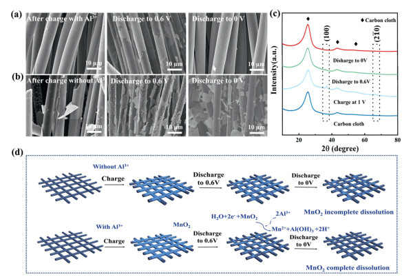
Ex-situ scanning electron microscope (SEM) characterizations of the cathode at different charge/discharge states are obtained to confirm the morphological and charge storage mechanism of electrodes with/without Al3+. Typical SEM images of the cathode in the electrolyte with Al3+ after the first charge in Fig. 2a exhibit the uniformly electrodeposited MnO2 layer coating on the surface of the carbon cloth. When discharged to 0.6 V, there is a sign of MnO2 coating layer dissolving and peeling off from the carbon cloth. After full discharged to 0 V, the MnO2 on the cathode disappears, restoring the pristine morphology of the clean carbon substrate. Fig. S1 (Supporting information) shows the enlarged SEM image of the carbon cloth after discharging to 0 V. It can be seen that almost no MnO2 remains on the carbon cloth after discharge. The element mapping images of the cathode in the Al2(SO4)3 + MnSO4 + ZnSO4 electrolyte is presented in Fig. S2 (Supporting information). At the full charge state, the Mn and O elements is uniform distribution on the carbon cloth. With the cutoff voltage of discharge decreasing, the contents of Mn and O elements gradually decrease with discharge, corresponding to the gradual dissolution of MnO2 from the carbon cloth. By contrast, the cathode without Al3+ after the first charge are shown in Fig. 2b, from which the nonuniformly electrodeposited MnO2 is coated on the surface of the carbon cloth. After discharging, there still remained many MnO2 residual on the surface of carbon cloth even after discharging to 0 V in without Al3+ electrolyte. As shown in Fig. 2c and Fig. S3 (Supporting information), after charging at 1.0 V for 0.5 mAh/cm2, new diffraction peaks appear at 37° and 67°, corresponding to the (110) and (21¯0) crystal facets of γ-MnO2 (PDF #30–0820, space group: P63/mmc), respectively. And it is gradually diminished in intensity until they vanish entirely upon reaching a full discharge to 0 V. These observations further support that Al3+ promotes more uniform MnO2 deposition during charging and facilitates more thorough MnO2 dissolution during discharge. The whole chemical process during cycling without or with Al3+ can be summarized in Fig. 2d. During charging, Mn2+ is oxidized to MnO2. During discharging, Al3+ promotes the dissolution of MnO2 into Mn2+ by providing H+, effectively consuming accumulated MnO2, thereby enhancing Coulombic efficiency, power density, and capacity of the battery.
Figure 2
Figure 2.
SEM images of the MnO2 cathode at different charge/discharge states: (a) With Al2(SO4)3 additive; (b) without Al2(SO4)3 additive. (c) Ex-situ XRD patterns of MnO2 cathode at different charge/discharge states with Al2(SO4)3 electrolyte. (d) A schematic illustration of the MnO2 cathode with/without Al2(SO4)3 during cycling.
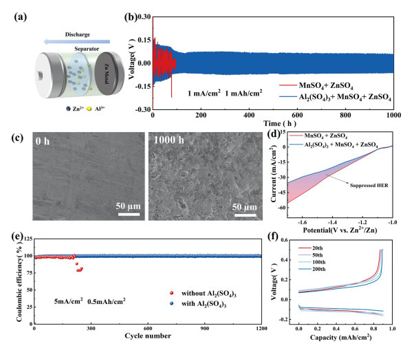
In addition to the cathode, ensuring the reaction stability of the Zn metal anode in the electrolyte is also important for the overall cell performance [49–51]. The long-term stability and reversibility of Zn anode in the different electrolytes were further investigated by using Zn//Zn symmetrical batteries, as displayed in Figs. 3a and b. Exceptional Zn plating/stripping behavior with excellent cycling durability (1000 h at 1 mA/cm2 with a capacity of 1 mAh/cm2) in the MnSO4 + ZnSO4 + Al2(SO4)3 electrolyte is illustrated. In contrast, the symmetrical cells exhibit unstable voltage fluctuation and shorter lifespans (< 100 h) in the MnSO4 + ZnSO4 electrolyte. This indicates that the additive of Al3+ promotes the uniform deposition of Zn2+ and improves the anti-corrosion performance of the Zn anode. It is probably due to that the Al3+ accumulates on the surface of Zn anode in the MnSO4 + ZnSO4 + Al2(SO4)3 electrolyte forming an electrostatic shielding layer to induce a compact and uniform Zn plating. The conclusion is supported by the SEM results in Fig. 3c, the Zn anode maintains a smooth and dense morphology without Zn dendrites or "dead" Zn in the MnSO4 + ZnSO4 + Al2(SO4)3 electrolyte after 1000 h of cycling. On the contrary, the Zn anode exhibits a rough and uneven morphology after cycling for nearly 100 h in the MnSO4 + ZnSO4 electrolyte (Fig. S4 in Supporting information). The digital graphs of the Zn anode after cycling 20 h clearly show smoother deposition in MnSO4 + ZnSO4 + Al2(SO4)3 electrolyte compared to MnSO4 + ZnSO4 electrolyte (Fig. S5 in Supporting information). As shown in Fig. S6 (Supporting information), the XRD patterns of zinc foil cycled in with Al2(SO4)3 electrolyte, were consistent with the initial pure zinc, and no additional by-products were observed. However, in the without Al2(SO4)3 electrolyte, peaks corresponding to a by-product appeared in the XRD pattern of the zinc foil after cycling. These results manifest that the Al2(SO4)3 introducing into the electrolyte will not only promote the MnO2 deposition/dissolution but also effectively inhibit the parasitic reaction of zinc anode, greatly improving the overall stability of the Zn//MnO2 batteries. Besides, the Zn anode demonstrates a higher hydrogen evolution reactions (HER) overpotential in the MnSO4 + ZnSO4 + Al2(SO4)3 electrolyte compared to the MnSO4 + ZnSO4 electrolyte (Fig. 3d), indicating effective mitigation of HER due to the existence of Al3+. This is mainly due to the fact that the electrostatic shielding effect provided by Al3+ inhibits the formation of Zn dendrites, thereby protecting the Zn metal from corrosion and HER during the cycle [52–54].
Figure 3
Figure 3.
(a) The schematic illustration of the Zn//Zn cells. (b) Cycling performance of Zn//Zn symmetrical cells at 1 mA/cm2 and 1 mAh/cm2. (c) SEM images of the Zn anode and after plating/stripping for 1000 h in MnSO4 + ZnSO4 + Al2(SO4)3 electrolyte. (d) Comparison of HER overpotential. (e) Coulombic efficiency of a Cu//Zn cell at 5 mA/cm2 and 0.5 mAh/cm2. (f) Corresponding charge/discharge curves of Zn//Cu cells.
The electrochemical stability of the Zn anode with Al3+ is further evaluated through CE performance measurements with Zn//Cu cells. Zn//Cu cells with Al3+ additive exhibits stable cycling for > 1200 cycles with an impressive average CE of 99.77% (Fig. 3e). In contrast, the Zn//Cu cell exhibits significantly lower CE and cycling stability when cycled in the MnSO4 + ZnSO4 electrolyte. The corresponding charge and discharge curves of the Zn//Cu cells in the MnSO4 + ZnSO4 + Al2(SO4)3 electrolyte is recorded in Fig. 3f. The presence of Al3+ significantly improves CE and extends the cycling stability of the Zn//Cu cells. As shown in Fig. S7 (Supporting information), the diffusion mechanisms of Zn deposition on the anode surface are examined using chronoamperometry (CA) in Zn//Zn cells. When the Zn electrode is placed in the MnSO4 + ZnSO4 + Al2(SO4)3 electrolyte, the current density remains steady after a short period of 2D diffusion. This behavior facilitates the deposition of fine-grained, uniformly distributed Zn. In contrast, when the Zn electrode is immersed in the MnSO4 + ZnSO4 electrolyte, the current density continues to increase gradually even after 50 s, indicating that a 2D diffusion process is still ongoing. This continuous rise in current density leads to the formation and growth of Zn dendrites. In summary, the MnSO4 + ZnSO4 + Al2(SO4)3 electrolyte ensures a uniform Zn deposition morphology, outstanding stability and compatibility of the Zn anode, enabling a dendrite-free and highly stable Zn anode with high CE. The excellent cycling stability and reversibility of Zn in the MnSO4 + ZnSO4 + Al2(SO4)3 electrolyte are crucial for high-performance Zn//MnO2 batteries.
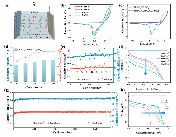
The full batteries of Zn//MnO2 in MnSO4 + ZnSO4 + Al2(SO4)3 electrolyte were investigated to check the practicality (Fig. 4a). The CV curves of Zn//MnO2 full batteries at different scan rates (from 0.5 mV/s to 2 mV/s) is depicted in Fig. 4b. At different scanning speeds, the shapes of CV curves are basically the same, indicating the fast reaction kinetics of this configuration in MnSO4 + ZnSO4 + Al2(SO4)3 electrolyte. As shown in Fig. 4c, CV curve of the Zn//MnO2 batteries in MnSO4 + ZnSO4 + Al2(SO4)3 electrolyte shows a completely different reduction peak compared to that in the MnSO4 + ZnSO4 electrolyte system, indicating a different charge storage mechanism. And the closed area of the batteries in MnSO4 + ZnSO4 + Al2(SO4)3 electrolyte is much higher than in MnSO4 + ZnSO4 electrolyte, further implying that the Al3+ great enhances the two-electron reactions of the Mn2+/MnO2. As shown in Fig. 4d, the discharge voltage and CE of the Zn//MnO2 batteries in MnSO4 + ZnSO4 + Al2(SO4)3 electrolyte is increased with each cycle. The Zn//MnO2 system also exhibits superior rate performance (Fig. 4e), maintaining a discharge capacity close to 0.5 mAh/cm2 even at a high current density of 10 mA/cm2. In addition, as shown in the Fig. S8 (Supporting information), the discharge voltage in with Al2(SO4)3 electrolyte is about 1.6 V, which is higher than many previous reports. It is indicated that the Al2(SO4)3 significantly facilitate the deposition/dissolution mechanism of Mn2+/MnO2, thus improving the electrochemical performance [55–58]. The corresponding discharge curves at different current densities in Fig. 4f demonstrate that nearly 99% of the charge capacity is preserved, even at the high current density of 10 mA/cm2. The long-term cycling performance and CE of the Zn//MnO2 battery at 2 mA/cm2 are presented in Fig. 4g. The battery with Al3+ exhibits a stable discharge capacity without noticeable decay for 1900 cycles at a charge capacity of 0.5 mAh/cm2, reaching a high CE of nearly 99%. Fig. 4h shows the charge and discharge curves of the Zn//MnO2 batteries for the first 200th cycles in the Al2(SO4)3 + MnSO4 + ZnSO4 electrolyte. The presence of Al3+ significantly improves discharge voltage and prolongs the cycling stability of the Zn//MnO2 battery. The superior cycling stability and rate capability are attributable to the highly reversible MnO2/Mn2+ deposition/dissolution reaction mechanism induced by Al3+.
Figure 4
Figure 4.
(a) Schematic illustration of the aqueous rechargeable Zn//MnO2 energy storage system in Al2(SO4)3 + MnSO4 + ZnSO4 electrolyte. (b) CV curves in Al2(SO4)3 + MnSO4 + ZnSO4 electrolyte. (c) Comparison of the CV curves in with/without Al2(SO4)3 aqueous electrolytes at 1 mV/s. (d) The discharge voltage of different cycle number in the with Al2(SO4)3 electrolyte. (e) Rate performance of the Zn//MnO2 battery with capacity of 0.5 mAh/cm2. (f) The corresponding charge/discharge profiles. (g) Long-term cycling performance of the Zn//MnO2 battery at 2 mA/cm2 and 0.5 mAh/cm2. (h) Galvanostatic discharge curves of the first 200 cycles.
In conclusion, owing to the effect of Al3+, the two-electron Mn4+/Mn2+ redox reaction is remarkably inspired, leading to a higher capacity with a higher voltage and superior cycling reversibility compared to the conventional Mn4+/Mn3+ redox reaction. In addition, the presence of Al3+ ensures outstanding stability and compatibility of the Zn anode and consequently enables a dendrite-free Zn anode with a high plating/stripping CE. As results, the assembled aqueous Zn//MnO2 battery demonstrates a high discharge voltage (1.6 V) and a long cycling stability (1900 cycles without decay). The anode-friendly electrolyte facilitates stable Zn plating/stripping and high Coulombic efficiency. This new strategy of enhancing Zn//MnO2 battery via Al3+ in the electrolyte provides a promising solution for large-scale energy storage applications.
Declaration of competing interest
The authors declare that they have no known competing financial interests or personal relationships that could have appeared to influence the work reported in this paper.
This work was supported by the Joint Funds of the National Natural Science Foundation of China (No. U22A20140), the Jinan City-School Integration Development Strategy Project (No. JNSX2023015), Independent Cultivation Program of Innovation Team of Ji’nan City (No. 202333042), the University of Jinan Disciplinary Cross-Convergence Construction Project 2023 (Nos. XKJC-202309, XKJC-202307), Higher-Level Talent Initial Scientific Research and Discipline Construction Fund (No. 511/1009530), National Natural Science Foundation of China (No. 22409071), and Natural Foundation of Shandong Province (No. ZR2024QB120).
Supplementary materials
Supplementary material associated with this article can be found, in the online version, at doi:10.1016/j.cclet.2025.111868.
Z. Liu, L. Li, L. Qin, et al., Adv. Mater. 34 (2022) 220468.
[57]
J, Lei, Y. Yao, Z. Wang, et al., Energy Environ. Sci. 14 (2021) 4418–4426. doi: 10.1039/D1EE01120K
[58]
X. Zeng, J. Liu, J. Mao, et al., Adv. Energy Mater. 10 (2020) 1904163. doi: 10.1002/aenm.201904163
Figure 1
(a) CV curves at 1 mV/s. (b) Galvanostatic discharge curves in various electrolytes based on a three-electrode system. (c) The cycling stability of the MnO2 cathode in with/without Al2(SO4)3 electrolyte. (d) Galvanostatic discharge curves in the first 100 cycles. (e) Schematic illustration of Al2(SO4)3 facilitating the MnO2 deposition/dissolution.
Figure 2
SEM images of the MnO2 cathode at different charge/discharge states: (a) With Al2(SO4)3 additive; (b) without Al2(SO4)3 additive. (c) Ex-situ XRD patterns of MnO2 cathode at different charge/discharge states with Al2(SO4)3 electrolyte. (d) A schematic illustration of the MnO2 cathode with/without Al2(SO4)3 during cycling.
Figure 3
(a) The schematic illustration of the Zn//Zn cells. (b) Cycling performance of Zn//Zn symmetrical cells at 1 mA/cm2 and 1 mAh/cm2. (c) SEM images of the Zn anode and after plating/stripping for 1000 h in MnSO4 + ZnSO4 + Al2(SO4)3 electrolyte. (d) Comparison of HER overpotential. (e) Coulombic efficiency of a Cu//Zn cell at 5 mA/cm2 and 0.5 mAh/cm2. (f) Corresponding charge/discharge curves of Zn//Cu cells.
Figure 4
(a) Schematic illustration of the aqueous rechargeable Zn//MnO2 energy storage system in Al2(SO4)3 + MnSO4 + ZnSO4 electrolyte. (b) CV curves in Al2(SO4)3 + MnSO4 + ZnSO4 electrolyte. (c) Comparison of the CV curves in with/without Al2(SO4)3 aqueous electrolytes at 1 mV/s. (d) The discharge voltage of different cycle number in the with Al2(SO4)3 electrolyte. (e) Rate performance of the Zn//MnO2 battery with capacity of 0.5 mAh/cm2. (f) The corresponding charge/discharge profiles. (g) Long-term cycling performance of the Zn//MnO2 battery at 2 mA/cm2 and 0.5 mAh/cm2. (h) Galvanostatic discharge curves of the first 200 cycles.


 DownLoad:

 下载:
下载:


 下载:
下载:

