Citation:
Houkui Xiang, Zhijian Wang, Jiazang Chen. Revealing the Role of Elementary Doping in Photocatalytic Phenol Mineralization[J]. Chinese Journal of Structural Chemistry,
2022, 41(9): 220906.
doi:
10.14102/j.cnki.0254-5861.2022-0097

Revealing the Role of Elementary Doping in Photocatalytic Phenol Mineralization
English
Revealing the Role of Elementary Doping in Photocatalytic Phenol Mineralization
Abstract:
Photocatalytic mineralization of recalcitrant contaminants like phenol in wastewater requires abundant hydroxyl radicals (·OH) to initiate the reaction prior to the ring-opening. We here increase the free energy for adsorption of O* species on TiO2 surface and slightly downshift the band position by tin doping. This can simultaneously promote the generation and suppress the annihilation of ·OH. Besides, tin doping can also facilitate semiconductor-cocatalyst-solution (SCS) interfacial electron transfer by lowering the potential barrier and synergistically enhance the photon utilization. By filming the photocatalyst onto our developed fixed bed reactors, the loss of photons resulting from undesirable absorption by contaminants can be alleviated. By these virtues, trace amount of phenol in wastewater can be efficiently mineralized.
-
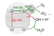
Photocatalytic degradation of recalcitrant contaminants like phenol has been considered as an important approach to wastewater treatment.[1, 2] This measure can generate strong oxidants like ·OH that can initiate the reaction and open the ring of phenol molecules.[3, 4] However, because of low rate and poor selectivity for ·OH generation, [5, 6] competition between the forward and side reactions (Figure 1), [7, 8] and undesirable light absorption by the contaminants (Figure S1), [9, 10] photocatalytic mineralization still suffers from low utilization of incident photons.
Figure 1

Efficient photocatalytic mineralization requires to rationally distribute photogenerated potential drop to simultaneously promote the hole extraction and SCS interfacial electron transfer that are closely correlative.[11, 14] This strategy can be realized by tuning the band edge position and electronic states of the semiconductor.[12-13] Although direct oxidation commonly used in value-added reaction is of efficient photon utilization, [11] the deposition and/or even polymerization of oxidized contaminants will undesirably deactivate the photocatalyst especially for the case with aromatic compounds.[15] Besides, the formation of complexes on the semiconductor surface will stabilize the contaminants.[16, 17] Thus, photocatalytic mineralization prefers to adopt semiconductor with weak adsorption of oxygen species to avoid the poisoning effect.[6] The chemical inertness requires very low valence band maximum (EVB) to endow the photogenerated holes with sufficient positive potential to drive the transfer of holes for ·OH formation.[6, 15] In addition to hole transfer, SCS interfacial electron transfer that occurs on decisecond-second timescale should be facilitated.[11-13]
Foreign elementary doping offers a feasible solution to facilitate the electronic processes appearing in photocatalytic reaction. In this work, we slightly downshift the band position of TiO2 by tin doping, which synergistically promotes the semiconductor-coca-talyst (SC) interfacial electron transfer and formation of ·OH. Besides, we also develop a reactor configuration to make the photocatalyst conductive to the competition of light absorption.
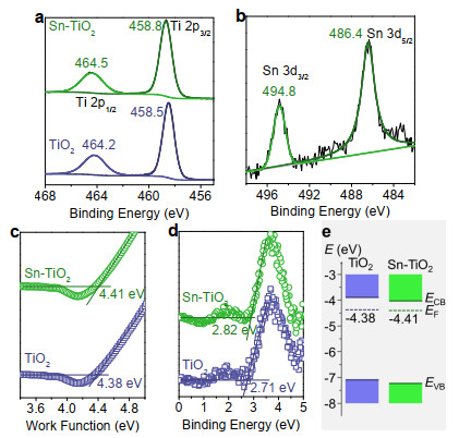
Let us begin with materials. Doping TiO2 with tin can be realized by solvothermal treatment of titanium-containing precursor in the presence of SnCl4. X-ray diffraction patterns and electron micro-scopy images show that TiO2 remains its original phase, morpho-logy, and size after doping with tin (Figure S2). Together with elemental analysis (Figure S2), the slight blueshift of Ti 2p peaks and presence of Sn 3d signal in the X-ray photoelectron spectra (XPS) suggest that electronic interaction occurs in the lattice after doping with tin (Figures 2a-b).[18] Besides, the tin dopant slightly downshifts the band edge and Fermi level of TiO2 (Figures 2c-e, S2). These phenomena indicate that efficient photocatalytic mineralization can be expected for the tin doped TiO2 (Sn-TiO2).
Figure 2
 Figure 2. The blueshift of Ti 2p peaks (a) and presence of Sn 3d (b) shown in XPS indicate that tin has been doped into the TiO2 lattice. The shift of work function (c) and band edge (d) slightly change the band alignment of TiO2 after elementary doping (e). The binding energy (d) for determining EVB can be obtained from the 2nd derivative of the ultraviolet photoelectron spectroscopy curves shown in Figure S2.
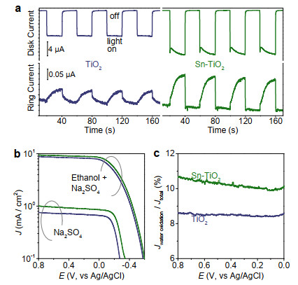
To validate the assumption, we here investigate the role of tin dopant on ·OH generation. Figure 3a shows the photoinduced anodic current increment of TiO2 and Sn-TiO2 deposited on the glassy carbon disk and the related cathodic signals on the platinum ring in a rotating ring-disk electrode (RRDE). Because nearly all the photogenerated electrons can be collected by the carbon substrate, the photoinduced current increment can reflect the extraction of photogenerated holes by the aqueous surrounding. The current increment for Sn-TiO2 is ~1.5 times higher than that of TiO2 (Figure 3a), indicating that the tin doping can facilitate the hole extraction. Accordingly, the cathodic current that reflects the generation of oxidation product is also evident for Sn-TiO2, as compared with that of TiO2. Besides, we also compare the voltammetry behaviors of the electrodes in solution with and without hole extractor, indicating the average contribution of water oxidation to the total current for Sn-TiO2 electrode is 10.38%, which is higher than that of 8.54% for TiO2 (Figure 3b-c). This information indicates that the tin dopant can facilitate the separation of photogenerated charge carriers and promote ·OH generation.
Figure 3
 Figure 3. Photoinduced anodic behaviors of TiO2 and Sn-TiO2 on the glassy carbon disk and the related cathodic current occurring on the platinum ring of the RRDE (a). Photoelectrochemical behaviors (b) and plateau current ratios for the electrodes in the Na2SO4 aqueous solution without (Jwater oxidation) and with (Jtotal) addition of ethanol (c).
To further verify the benefit of tin dopant to ·OH generation, we investigate the photoinduced behaviors of TiO2 and Sn-TiO2 dispersed in 2 mM NaOH aqueous solution that contains 0.5 mM terephthalic acid (TA) for trapping ·OH. As estimated from the TA-OH photoluminescence intensity (Figure S3), the average gene-ration rate of ·OH for Sn-TiO2 is 5.67 μmol g-1 h-1, which is ~1.5 times higher than that of 3.76 μmol g-1 h-1 for TiO2. This information obtained from the dispersed system is consistent with that evaluated from photoelectrochemical cells (Figure 3) and further confirms that the tin dopant can facilitate the generation of ·OH.
Generally, the products of water oxidation are sensitively dependent on the adsorption free energy of relevant intermediates.[6] The weak adsorption of oxygen species (O*) on TiO2 makes the formation of adsorbed OH very high energy, which is close to the potential for solvation of hydroxyl (i.e.: formation of free ·OH). This means that the weakening of O* adsorption is beneficial to the formation of ·OH. The adsorption of O* on TiO2 can be adjusted by tunning the electronic states, for example, creation of oxygen vacancy to strengthen the interaction or further depriving the negative charge from Ti4+ sites to weaken the adsorption.[4, 19] In our case, the blueshift of Ti 2p peaks (Figure 2a) indicates that the electronic interaction for the adsorption of O* on TiO2 becomes weak after doping with tin (Figure S4).[19] This can give a rational explanation for the efficient generation of ·OH for Sn-TiO2. Besides, the weak adsorption of O* not only retards the formation of H2O2 prior to desorption, [6, 20] but also suppresses the annihilation of ·OH with the non-target species in the vicinity of the generation sites, for example, the electrons in the semiconductor (Figure S5). This can improve the utilization of photogenerated ·OH.
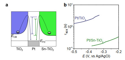
In addition to facial generation of ·OH, efficient photocatalytic mineralization requires to address the issue of very slow SC interfacial electron transfer, which is sensitively dependent on the height of potential barrier.[13, 21-23] As estimated from the ultraviolet photoelectron spectroscopy investigation, the conduction band edge slightly downshifts after doping TiO2 with tin (Figure 2e). Similar phenomenon can also be observed from the voltammetry behaviors of TiO2 and Sn-TiO2 (Figure S6). By virtue of lowering the conduction band, the favorable band alignment with lowered potential barrier for SC interfacial electron transfer can be formed for Sn-TiO2 contacting with metal like platinum (Figure 4a).[11, 21-24]
Figure 4
 Figure 4. Schematic diagram (a) shows that the slight downshifts of conduction band of electronic Fermi level can lower the potential barrier and facilitate SM interfacial electron transfer (b). The time constant for SCS interfacial electron transfer can be evaluated from the parameters obtained from OCP behaviors (Figures S5, S7).
To validate this assumption, we monitor the decay behaviors of open-circuit potential (OCP) of the electrode upon cutting off the irradiation. OCP decay has widely been used to characterize the leakage of electrons from semiconductor electrodes[25, 26] and has recently been extended to estimate the time constant for SC interfacial electron transfer in photocatalytic reactions.[11-13] The time constant (τSC) for SC interfacial electron transfer can be obtained by separating the parameters evaluated from OCP behaviors of semiconductor with (τOCP-dual) and without (τOCP) loading of cocatalyst (e.g.: Pt): [13]
$ \frac{1}{{\tau }_{\text{TP}}+{\tau }_{\text{SC}}+{\tau }_{\text{EC}}}=\frac{1}{{\tau }_{\text{OCP-dual}}}-\frac{1}{{\tau }_{\text{OCP}}}=\frac{1}{{\tau }_{\text{SCS}}} $ (1a) in which τTP (timescale: ps-ns) and τEC (timescale: μs-ms) respectively represent the time constants for transport of electrons in the semiconductor and electrochemical transfer of electrons to the solution that are negligibly small.[27] τSC can be described by the time constant for SCS interfacial electron transfer (τSCS):
$ {\tau }_{\text{SCS}}={\tau }_{\text{TP}}+{\tau }_{\text{SC}}+{\tau }_{\text{EC}}\approx {\tau }_{\text{SC}} $ (1b) τOCP-dual and τOCP can be obtained by monitoring OCP decay: [13, 25]
$ {\tau }_{\text{OCP(-dual)}}=\frac{{k}_{\text{B}}T}{q}{\left(\frac{\text{d}E}{\text{d}t}\right)}^{-1} $ (2) in which kB is the Boltzmann constant, T is the temperature, q is the elementary charge, and E is the potential at a given time, t.
Because TiO2 is generally inert to the hydrogen evolution, the time constants for charge leakage reach several seconds to ~10 seconds (Figure S5). By doping TiO2 with tin, the photoinduced potential shifts to more negative value and the OCP decay becomes further slow (Figure S5) because tin dopant can passivate the surface activity. Sn-TiO2 therefore exhibits much larger time constants (> 30 s) for electron leakage than TiO2 (Figure S5). By loading with platinum, the decay of OCP becomes rapid (Figure S7). The time constants for transfer of electrons from Sn-TiO2 to platinum is several deciseconds, which is 10 times smaller than that of ~1-4 seconds for Pt/TiO2 (Figure 4b).
The photocatalytic mineralization generally introduces oxygen/air into reaction systems. To meet the requirement of practical application, we also monitor the decay behaviors of photoinduced OCP in the presence of oxygen. Because oxygen reduction can occur on more positive potential than hydrogen evolution (Figure S7), OCP decay becomes rapid and the photoinduced potentials turn less negative (Figure 5a). Although the OCP decay can be further accelerated by loading platinum, the decrement in timescale is not as evident as that without oxygen especially for the case of TiO2 (Figures 5b, S4). This is because TiO2 exhibits considerable activity for oxygen reduction for releasing electrons to the solution (Figures 5c, S4).
Figure 5
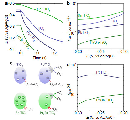
 Figure 5. OCP decay behaviors (a) of electrodes in oxygen bubbled 0.5 M Na2SO4 solution upon light off and the estimated time constants (b). Tin doping can effectively suppress electron leakage (c) and facilitate SCS interfacial electron transfer after loading with platinum (d).
Like the situation without oxygen (Figures 4, S5, S7), the tin dopant can also suppress the leakage of electrons from semiconductor and facilitate SM interfacial electron transfer in the presence of oxygen (Figure 5).
It is noteworthy that the photoinduced potential for Pt/Sn-TiO2 is less negative than that for Pt/TiO2 (Figures 5, S7) because the tin dopant can lower SC contact barrier and save the energy (potential drop) dissipation for SCS interfacial electron transfer. The positive shift of potential can reduce the density of electrons and simultaneously increase the population of holes in the semiconductor (Figures 5c, 6)[28] as the product of the density of electrons and holes in the semiconductor can be nearly constant under thermal equilibrium. The increase in the density of holes in semiconductor can synergistically facilitate the ·OH generation and oxidation half-reaction (Figures 3b, 6).
Figure 6
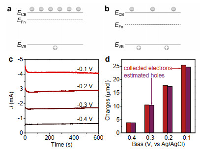
 Figure 6. Schematic diagrams for Fermi level and hole population of semiconductor biased at more (a) and less (b) negative potential in the solution under irradiation. The amperometry behaviors of TiO2 electrodes in ethanol aqueous solution (10 vol% ethanol + 0.5 M Na2SO4) also shows that photocurrent increases as the bias potential becomes less negative (c). By measuring the accumulated oxidation product, the number of holes estimated from the generated acetaldehyde is very close to the number of the collected electrons evaluated from the amperometry behaviors (d).
We now discuss photocatalytic mineralization. To alleviate the loss of photons absorbed by contaminant, we here develop a fixed bed reactor (Figure 7a).[29] In this configuration, the incident light should first strike on the fixed film photocatalyst and the absorption of photons by phenol molecules can be minimized. This configuration can effectively improve the photon utilization for photocatalytic mineralization of contaminants from wastewater that contains light-absorbing substance (Figure S8).
Figure 7
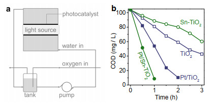
 Figure 7. Schematic diagram for fixed bed photocatalytic reactor (a) and the photocatalytic mineralization of phenol on TiO2, Sn-TiO2, Pt/TiO2 and Pt/Sn-TiO2 films (b).
Because tin dopant can facilitate ·OH generation and SCS interfacial electron transfer, Pt/Sn-TiO2 exhibits most efficient photocatalytic phenol mineralization (Figure 7b). Nearly all the phenol (42 mg/L × 1 L, chemical oxygen demand, COD = ~100 mg/L) in water can be mineralized and COD reduced to 8.7 mg/L after 1 h irradiation. Following a descending order is Pt/TiO2 (Figure 7b), which requires 2 h to mineralize the contaminant and reduces the COD to 10.4 mg/L. Although tin dopant offers favorable selectivity for ·OH generation (Figure 3c), the excessive accumulation of electrons will suppress the survival and interfacial transfer of holes (Figure 6).[14, 28] This will undesirably slow the reaction over Sn-TiO2. In contrast, because the release of electrons to solution is relatively fast (Figure S5), the COD removal by TiO2 is faster than that for Sn-TiO2 (Figure 7b). After 3 h irradiation, the respective COD values for TiO2 and Sn-TiO2 are 42.8 and 60.2 mg/L.
CONCLUSION
We have demonstrated that tin dopant in TiO2 can facilitate the photoinduced generation and suppress the annihilation of hydroxyl radicals. This elementary doping maximizes the role of cocatalyst by promoting the interfacial transfer of electrons to the solution. Together with the fixed bed reactors for efficient light absorption by photocatalyst, the design of electronic processes provides important hints for photocatalytic wastewater treatment.
ACKNOWLEDGEMENTS: The authors acknowledge National Natural Science Foundation of China (Nos. 22172185, 21773285, and U1932128), CAS Western Youth Scholars Program (No. XAB2019AW09), Fund Program for the Scientific Activities of Selected Returned Overseas Professionals in Shanxi Province (No. 20220051), CAS Pioneer "Hundred Talents Program", and the Start-up Grant of Institute of Coal Chemistry for financial support. The authors declare no competing interests.
COMPETING INTERESTS
For submission: https://www.editorialmanager.com/cjschem
Supplementary information is available for this paper at http://manu30.magtech.com.cn/jghx/EN/10.14102/j.cnki.0254-5861.2022-0097
ADDITIONAL INFORMATION
-
-
[1]
Parvulescu, V. I.; Epron, F.; Garcia, H.; Granger, P. Recent progress and prospects in catalytic water treatment. Chem. Rev. 2022, 122, 2981-3121. doi: 10.1021/acs.chemrev.1c00527
-
[2]
Cheng, Z.; Ling, L.; Shang, C. Near-ultraviolet light-driven photocata-lytic chlorine activation process with novel chlorine activation mechanisms. ACS ES & T Water 2021, 1, 2067-2075.
-
[3]
Park, H.; Park, Y.; Kim, W.; Choi, W. Surface modification of TiO2 photocatalyst for environmental applications. J. Photochem. Photobio. C 2013, 15, 1-20. doi: 10.1016/j.jphotochemrev.2012.10.001
-
[4]
Luo, T.; Wang, Z.; Wei, X.; Huang, X.; Bai, S.; Chen, J. Surface enriching promotes decomposition of benzene from air. Catal. Sci. Technol. 2022, 12, 2340-2345.
-
[5]
Tao, H. B.; Xu, Y.; Huang, X.; Chen, J.; Pei, L.; Zhang, J.; Chen, J. G.; Liu, B. A general method to probe oxygen evolution intermediates at operating conditions. Joule 2019, 3, 1498-1509. doi: 10.1016/j.joule.2019.03.012
-
[6]
Siahrostami, S.; Li, G. L.; Viswanathan, V.; Nørskov, J. K. One- or two-electron water oxidation, hydroxyl radical, or H2O2 evolution. J. Phys. Chem. Lett. 2017, 8, 1157-1160.
-
[7]
Schneider, J.; Matsuoka, M.; Takeuchi, M.; Zhang, J.; Horiuchi, Y.; Anpo, M.; Bahnemann, D. W. Understanding TiO2 photocatalysis: mechanisms and materials. Chem. Rev. 2014, 114, 9919-9986. doi: 10.1021/cr5001892
-
[8]
Hoffmann, M. R.; Martin, S. T.; Choi, W.; Bahnemann, D. W. Environmental applications of semiconductor photocatalysis. Chem. Rev. 1995, 95, 69-96. doi: 10.1021/cr00033a004
-
[9]
Malato, S.; Fernández-Ibáñez, P.; Maldonado, M. I.; Blanco, J.; Gernjak, W. Decontamination and disinfection of water by solar photocatalysis: recent overview and trends. Catal. Today 2009, 147, 1-59. doi: 10.1016/j.cattod.2009.06.018
-
[10]
Awfa, D.; Ateia, M.; Fujii, M.; Yoshimura, C. Photocatalytic degradation of organic micropollutants: inhibition mechanisms by different fractions of natural organic matter. Water Res. 2020, 174, 115643. doi: 10.1016/j.watres.2020.115643
-
[11]
Wang, Z.; Mei, B.; Chen, J. Removing semiconductor-cocatalyst interfacial electron transfer induced bottleneck for efficient photocatalysis: a case study on Pt/CdS photocatalyst. J. Catal. 2022, 408, 270-278. doi: 10.1016/j.jcat.2022.03.014
-
[12]
Xu, Y.; Wang, Z.; Xiang, H.; Yang, D.; Wang, J.; Chen, J. Revealing the role of electronic doping for developing cocatalyst-free semiconducting photocatalysts. J. Phys. Chem. Lett. 2022, 2039-2045.
-
[13]
Xiang, H.; Wang, Z.; Chen, J. Revealing and facilitating the rate-determining step for efficient sunlight-driven photocatalysis. J. Phys. Chem. Lett. 2021, 12, 7665-7670.
-
[14]
Yang, D.; Wang, Z.; Chen, J. Revealing the role of surface elementary doping in photocatalysis. Catal. Sci. Technol. 2022, 10.1039/d2cy00410k.
-
[15]
Panizza, M.; Cerisola, G. Direct and mediated anodic oxidation of organic pollutants. Chem. Rev. 2009, 109, 6541-6569.
-
[16]
Shi, J. L.; Hao, H.; Lang, X. Phenol-TiO2 complex photocatalysis: visible light-driven selective oxidation of amines into imines in air. Sus. Energy Fuels 2019, 3, 488-498.
-
[17]
Xu, H.; Shi, J. L.; Lyu, S.; Lang, X. Visible-light photocatalytic selective aerobic oxidation of thiols to disulfides on anatase TiO2. Chin. J. Catal. 2020, 41, 1468-1473.
-
[18]
Li, J.; Zeng, H. C. Hollowing Sn-doped TiO2 nanospheres via Ostwald ripening. J. Am. Chem. Soc. 2007, 129, 15839-15847.
-
[19]
Tao, H. B.; Fang, L.; Chen, J.; Yang, H. B.; Gao, J.; Miao, J.; Chen, S.; Liu, B. Identification of surface reactivity descriptor for transition metal oxides in oxygen evolution reaction. J. Am. Chem. Soc. 2016, 138, 9978-9985.
-
[20]
Nosaka, Y.; Nosaka, A. Understanding hydroxyl radical (·OH) generation processes in photocatalysis. ACS Energy Lett. 2016, 1, 356-359.
-
[21]
Chen, J.; Li, B.; Zheng, J.; Zhao, J.; Zhu, Z. Role of carbon nanotubes in dye-sensitized TiO2-based solar cells. J. Phys. Chem. C 2012, 116, 14848-14856.
-
[22]
Wang, Z.; Qiao, W.; Yuan, M.; Li, N.; Chen, J. Light-intensity-dependent semiconductor-cocatalyst interfacial electron transfer: a dilemma of sunlight-driven photocatalysis. J. Phys. Chem. Lett. 2020, 11, 2369-2373.
-
[23]
Wang, Z.; Xue, N.; Chen, J. Semiconductor-cocatalyst interfacial electron transfer dominates photocatalytic reaction. J. Phys. Chem. C 2019, 123, 24404-24408.
-
[24]
Chen, J.; Zhang, L.; Lam, Z.; Tao, H. B.; Zeng, Z.; Yang, H. B.; Luo, J.; Ma, L.; Li, B.; Zheng, J.; Jia, S.; Wang, Z.; Zhu, Z.; Liu, B. Tunneling interlayer for efficient transport of charges in metal oxide electrodes. J. Am. Chem. Soc. 2016, 138, 3183-3189.
-
[25]
Zaban, A.; Greenshtein, M.; Bisquert, J. Determination of the electron lifetime in nanocrystalline dye solar cells by open-circuit voltage decay measurements. ChemPhysChem 2003, 4, 859-864.
-
[26]
Bisquert, J.; Zaban, A.; Greenshtein, M.; Mora-Sero, I. Determination of rate constants for charge transfer and the distribution of semiconductor and electrolyte electronic energy levels in dye-sensitized solar cells by open-circuit photovoltage decay method. J. Am. Chem. Soc. 2004, 126, 13550-13559.
-
[27]
Li, R.; Li, C. Chapter one-photocatalytic water splitting on semi-conductor-based photocatalysts. In Advances in Catalysis, Song, C., Ed. Academic Press. 2017, 60, pp 1-57.
-
[28]
Luo, J.; Chen, J.; Wu, B.; Goh, T. W.; Qiao, W.; Ku, Z.; Yang, H. B.; Zhang, L.; Sum, T. C.; Liu, B. Surface rutilization of anatase TiO2 for efficient electron extraction and stable Pmax output of perovskite solar cells. Chem 2018, 4, 911-923.
-
[29]
Chen, J.; Wei, X.; Xiang, H. Photocatalytic reaction device and method for wastewater treatment. CN 113620375 A 2021.
-
[1]
-
Figure 2 The blueshift of Ti 2p peaks (a) and presence of Sn 3d (b) shown in XPS indicate that tin has been doped into the TiO2 lattice. The shift of work function (c) and band edge (d) slightly change the band alignment of TiO2 after elementary doping (e). The binding energy (d) for determining EVB can be obtained from the 2nd derivative of the ultraviolet photoelectron spectroscopy curves shown in Figure S2.
Figure 3 Photoinduced anodic behaviors of TiO2 and Sn-TiO2 on the glassy carbon disk and the related cathodic current occurring on the platinum ring of the RRDE (a). Photoelectrochemical behaviors (b) and plateau current ratios for the electrodes in the Na2SO4 aqueous solution without (Jwater oxidation) and with (Jtotal) addition of ethanol (c).
Figure 4 Schematic diagram (a) shows that the slight downshifts of conduction band of electronic Fermi level can lower the potential barrier and facilitate SM interfacial electron transfer (b). The time constant for SCS interfacial electron transfer can be evaluated from the parameters obtained from OCP behaviors (Figures S5, S7).
Figure 5 OCP decay behaviors (a) of electrodes in oxygen bubbled 0.5 M Na2SO4 solution upon light off and the estimated time constants (b). Tin doping can effectively suppress electron leakage (c) and facilitate SCS interfacial electron transfer after loading with platinum (d).
Figure 6 Schematic diagrams for Fermi level and hole population of semiconductor biased at more (a) and less (b) negative potential in the solution under irradiation. The amperometry behaviors of TiO2 electrodes in ethanol aqueous solution (10 vol% ethanol + 0.5 M Na2SO4) also shows that photocurrent increases as the bias potential becomes less negative (c). By measuring the accumulated oxidation product, the number of holes estimated from the generated acetaldehyde is very close to the number of the collected electrons evaluated from the amperometry behaviors (d).
-

 DownLoad:

 下载:
下载:


 扫一扫看文章
计量
- PDF下载量: 17
- 文章访问数: 854
- HTML全文浏览量: 70
 下载:
下载:
