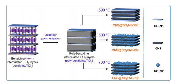
Figure 1.
Scheme illustration of CNS@TiO2NS-500, CNS@TiO2SNP-600, and CNS@TiO2LNP-700
In-situ Growth of Carbon Nanosheets Intercalated with TiO2 for Improving Electrochemical Performance and Stability ofLithium-ion Batteries
Yan-Jie HU , Yan-Hong YIN , Ming ZHANG , Zi-Ping WU , Zhong-Rong SHEN

Titanium dioxide (TiO2) has been widely investigated as an electrode material for lithium-ion batteries due to its safety, rich resources, and high theoretical specific capacity. But its low electronic conductivity leads to the poor rate performance and low cycle stability, and further limits its wide application[1]. To improve the lithium storage capability, rate performance, and cycle stability, the porosity of TiO2 is usually increased to alleviate the volume expansion, and the crystal particle size is reduced to improve the cycle stability[2]. However, the most efficient strategy is to combine TiO2 with carbon nanomaterials for increasing their contact area and conductivity, such as combining TiO2 with carbon nanofibers by electrospinning, vapor deposition[3-5], in-situ growth of TiO2 on carbon nanotubes[6, 7], intercalation of TiO2 in the interlayers of graphene[8-16] and so on. Based on the above strategies, the conductivity of TiO2-based materials can be enhanced, and thus the rate performance and cycle stability performance can be further improved. Nevertheless, the high length-width ratio and hydrophobic surface of carbon nanotubes inevitably limit their homogeneous dispersion, further inhibiting uniform distribution of TiO2 nanoparticles. Meanwhile, the reported carrier function of graphene is not satisfactory, and the main reason is the fact that the interaction force between graphene and TiO2 nanoparticles is weak, which is mainly ascribed to less functional groups in its plane except at the edge part. Therefore, it is vital to develop a more efficient route to synthesize carbon nanomaterials integrated with TiO2 nanoparticles.
Recently, our group prepared a layered composite material combined with carbon nanosheets and TiO2 layers by using amines as carbon source, through a procedure of intercalation, polymerization, and carbonization[17-19]. This composite exhibits a much higher theoretical capacity compared to TiO2, which is ascribed to the synergistic effect of ion insertion (conversion reaction) and interfacial capacitance effect (electric double layer effect)[20, 21]. In our previous work, Ni element was introduced to control the shape of layered TiO2. However, it would be removed by wet etching after carbonization process. The preparation procedure is complicated, eventually resulting in some oxygen vacancies existing in the TiO2 lattice.
In order to simplify the preparation process, herein, a strategy for in-situ growth of carbon nanosheets (CNS) was performed by using benzidine as carbon source. Based on the ability of benzylamine to increase the interlayer distance of HTO, the benzidine can be easily embedded between the interlayers of HTO by replacing benzylamine through an exchange reaction. The in-situ grown CNS can effectively improve the conductivity of TiO2. The morphology and size of TiO2 can be mediated through controlling carbonization temperatures. The obtained CNS@TiO2SNP-600 displays excellent electrochemical performance and high cycle stability, which is mainly due to the intercalated structure of CNS and TiO2. We believe this type of materials can be widely used in lithium-ion batteries and other related green chemical applications.
Benzylamine (C7H9N, 98.5%, Sinopharm Chemical Reagent Co., Ltd), benzidine (C12H12N2, 99.5%, Yuanhang Reagent, China) and potassium carbonate (K2CO3, 99.0%, Sinopharm Chemical Reagent Co., Ltd). K2CO3 was placed in an oven at 120 ℃ for 24 hours to remove moisture before the experiment.
HTO was firstly synthesized according to the method reported by Sasaki and his colleagues[22], and its morphology is displayed in Fig. S1. Then, the poly-benzidine/TiO2 sample was obtained through the process of intercalation, oxidative, and polymerization of benzidine by using HTO as template[18]. Finally, the poly-benzidine/TiO2 nanosheet was carbonized at 500, 600, and 700 ℃ in a reducing atmosphere (H2/N2 = 1/9 in V/V). Carbon nanosheets@TiO2 nanosheets (CNS@TiO2NS-500), carbon nanosheets@TiO2 small-sized nanoparticles (CNS@TiO2SNP-600), and carbon nanosheets@TiO2 large-sized nanoparticles (CNS@TiO2LNP-700) were obtained under different carbonization temperature of 500, 600, and 700 ℃ (Fig. 1), respectively.
In order to further characterize the physical properties of carbon nanosheets coated on TiO2, TiO2 was removed from the CNS@TiO2NS-500, CNS@TiO2SNP-600, and CNS@TiO2LNP-700. In a typical experiment, 1.0 g of CNS@TiO2NS-500, CNS@TiO2SNP-600, and CNS@TiO2LNP-700 was soaked in 25 mL 10 wt% HF aqueous solution, with the hydrothermal reaction kept at 100 ℃ for 12 h. Then, the reaction system was cooled down to room temperature, filtered, washed with deionized water and ethanol for several times. After drying at 60 ℃ overnight, the corresponding CNS products at different temperature are labeled as CNS-500, CNS-600, and CNS-700, respectively.
The composition of all samples was analyzed by X-ray diffraction (XRD) spectra, using a Rigaku MiniFlex 600 diffractometer with CuKα irradiation. The chemical structure and properties of the samples were characterized by Fourier Transform Infrared Spectrometer (FTIR, Thermo Nicolet is 50, USA), Raman spectra (Lab RAM Aramis spectrometer, 532 nm laser), Scanning Electron Microscope (SEM, Zeiss Sigma 500), and Transmission Electron Microscope (TEM, FEI Talos 200s microscope equipped with a high-precision EDX spectroscopy detector). Thermogravimetric Analysis (TGA, Mettler-Toledo TGA System) was performed at 5 ℃⋅min-1 from 30 to 800 ℃ in oxygen atmosphere.
Galvanostatic charge/discharge cycling tests were conducted on a Neware battery cycler (Neware, Shenzhen) within a cut-off voltage window between 0.05 and 3.0 V. Cyclic Voltammetry (CV) behaviors of the cells were conducted on a 760E electrochemical workstation (Chenhua, Shanghai) with a scan rate between 0.1 and 1 mV⋅s-1 in the voltage range of 0.05~3.0 V. Working-electrodes were prepared from 80 wt% activate material, 10 wt% valcun carbon XC-72 (Cabot, USA) and 10 wt% polyvinylidene fluoride (PVDF, HSV900, Kejing). The electrode slurry was coated on an copper foil (with doctor blade to control thickness) and dried overnight at 110 ℃ under vacuum. Standard CR2032-type coin cells were used to conduct electrochemical testes, by using activated material coated on copper foil (1 mg⋅cm-2 of loading mass), a metallic lithium foil and a Celgard 2500 as cathode, anode, and separator, respectively. 1.0 M LiPF6 in ethylene carbonate (EC)/diethylene carbonate (DEC) (V/V = 1:1) was used as the electrolyte. All the cells were aged overnight prior to the electrochemical measurements. The relative specific capacity was calculated based on the loading mass of active material.
Layered TiO2 was used as the template, and it was intercalated by Benzidine between the interlayer. After polymerization and carbonization, three types of CNS@TiO2 models (CNS@TiO2NS-500, CNS@TiO2SNP-600, and CNS@TiO2LNP-700) were obtained. The typical scheme illustration is displayed in Fig. 1.
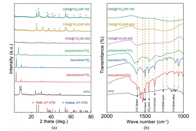
According to the periodic diffraction peak (0k0) (k = 1, 2, 3, …) shown in XRD pattern, the interlayer distance of materials with a typical layered structure can be obtained from the Bragg equation. The XRD pattern of benzylamine intercalated in HTO is exhibited in Fig. 2a. The diffraction characteristic peak located at 9.96° corresponds to the (010) plane of the layered HTO, and the interlayer distance is calculated to be 8.9 Å. The periodic diffraction peaks shift to a lower angle, and thus the interlayer distance increases. We can conclude that the organic amine has been embedded between the interlayers of HTO. As is known to us, the increased interlayer distance is determined by the type of material between the layers, and the value is equal to the molecular chain length of benzylamine and benzidine, which was reported in our previous study[18]. After benzylamine was embedded between HTO layers through an acid-base neutralization reaction, the diffraction period peak of benzylamine/TiO2 (010) shifts to a lower angle (Fig. 2a), and the interlayer distance is calculated to be 18.4 Å. We can find that the increased interlayer distance is twice as long as the molecular chain length of benzylamine (Table 1), indicating that benzylamine interacts with the upper and lower layers of the HTO.
 DownLoad:
CSV
DownLoad:
CSV
| Sample | HTO | Benzylamine/TiO2 | Benzidine/TiO2 | Polybenzidine/TiO2 |
| 2 Theta (°) | 9.96 | 4.82 | 5.01 | 7.24 |
| Interlayer distance (Å) | 8.9 | 18.4 | 17.8 | 12.2 |
Benzylamine can be easily embedded between the interlayers of the HTO template. However, it has a low boiling point, and only possesses one amino group that can be connected to the template. When large amounts of benzylamine are utilized as the carbon source, it usually escapes from the reaction system during the carbonization process, and even causes the collapse of the layered HTO template. Benzidine, an organic molecule with two amino groups, shows a high boiling point of 400 ℃, and can be carbonized at low temperature[23]. In this study, benzylamine was embedded into the HTO template through a wedge effect to increase the interlayer distance of HTO. And then benzidine was successfully embedded between the layers of HTO through an exchange reaction (Fig. 2a). Benzidine, containing additional two amino groups, can interact with the upper and lower layers of the HTO template. Therefore, it can maintain the structural integrity and reduce the loss of carbon source under high-temperature conditions. The interlayer distance of benzidine/TiO2 is 17.8 Å, and the increased interlayer distance is the length of the chain molecule of benzidine after the exchange reaction (Table 1).
Fourier transform infrared spectroscopy (FT-IR) spectrum demonstrates that the typical characteristic peaks (C–N (alkyl)) of benzylamine/TiO2 appear at 1060, 1116, and 1215 cm-1 (Fig. 2b), indicating the successful intercalation of benzidine into the interlayers of the HTO template after the replacement of benzylamine. A new typical characteristic peak (C–N (aryl)) of benzidine/TiO2 appears at 1264 cm-1, which demonstrates that benzidine has been successfully embedded into the HTO layers[24, 25]. In order to reduce the weight loss of benzidine during high-temperature carbonization process, the benzidine/TiO2 was put in a tube furnace and pre-polymerized at 200 ℃ for 3 hours under oxygen atmosphere. And then the polybenzidine/TiO2 was obtained. Compared with the benzidine/TiO2, the layered periodic diffraction peaks of polybenzidine/TiO2 shift to a larger angle (Fig. 2b). It demonstrates that benzidine can partially escape from the lath-shaped HTO layers, resulting in a decrease in the interlayer distance. The morphology of the polybenzidine/TiO2 maintains the intact structure of the HTO template during the process of intercalation, replacement, and polymerization (Fig. S2a~2c).
There are no obvious periodic diffraction peaks for CNS@TiO2NS-500 from the XRD spectrum (Fig. 2a). The possible reason is that the small size of the HTO template shows a weaker force and few restrictions of the organic molecules between the interlayers after carbonization. Therefore, obvious distortion of bonds and increased disorder of the interlayer distance[23] are easily observed. However, the CNS@TiO2NS-500 still maintains a regular layered structure as displayed in Fig. 4a.
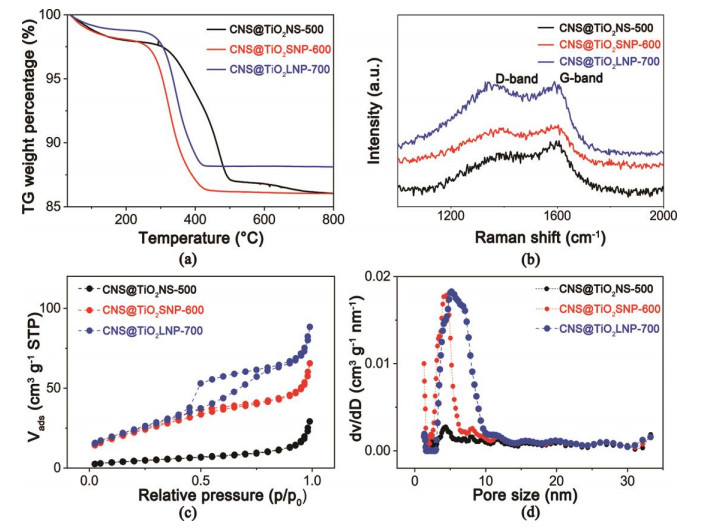
Under the calcination temperature of 600 ℃, the crystal structure of TiO2 undergoes a phase transformation. Diffraction peaks of anatase crystal structure in CNS@TiO2SNP-600 are obviously observed from the XRD spectrum (Fig. 2a). According to the Scherer's formula, the size of anatase TiO2 nanoparticles is calculated to be 16.9 nm. Obvious diffraction peaks of both anatase and rutile crystal structure appear in the XRD spectrum of the CNS@TiO2LNP-700 (Fig. 2a). The size of rutile TiO2 nanoparticles is calculated to be 57.0 nm. The larger size of TiO2 nanoparticles tends to restrict the improvement of storage capacity of interfacial lithium ions. Rutile TiO2 is more stable than anatase TiO2, and can accommodate < 0.1 moL Li+ per TiO2 unit. The existing rutile TiO2 tends to further restrict the lithium storage capacity of CNS@TiO2LNP-700[26-28]. The FT-IR spectra of polybenzidine/TiO2 (Fig. 2b) demonstrate that the numbers of C–H, N–H, and CH2 vibration peaks are significantly reduced, further confirming that the polymerization reaction is a process of dehydrogenation and deamination. After carbonization at 500, 600, and 700 ℃, no vibration absorption peaks of N–H, C–H, and CH2 appear in the FT-IR spectra of CNS@TiO2NS-500, CNS@TiO2SNP-600, and CNS@TiO2LNP-700. These results indicate that the polybenzidine/TiO2 has been completely carbonized without obvious change of the layered structure (Fig. S2d~2f). The color of all samples changes from yellow to black after the carbonization treatment (Fig. S2g). As presented in Fig. 3a, carbon contents in CNS@TiO2NS-500, CNS@TiO2SNP-600, and CNS@TiO2LNP-700 are 12.3%, 12.3%, and 10.8%, respectively. A very small difference in carbon content does not bring about a large difference in the electrochemical performance of the corresponding composite materials.
Raman spectra were used to detect carbon structure as shown in Fig. 3b, D peak (carbon atom lattice defects) and G peak (sp2 bond phonon vibration of carbon atom) appear at 1349 and 1596 cm-1 for carbon materials, respectively. The ratio of D and G bands (ID/IG) for the CNS@TiO2NS-500, CNS@TiO2SNP-600, and CNS@TiO2LNP-700 is 0.89, 0.95, and 1.02, respectively. With the increasement of calcination temperature, the corresponding CNS@TiO2NS-500, CNS@TiO2SNP-600, and CNS@TiO2LNP-700 exhibits higher degree of disorder in the carbon sheets, which is beneficial to improve the electrical conductivity of TiO2 in the composite[29-31].
As shown in Fig. 3c, BET measurement indicates CNS@TiO2NS-500 shows a small specific surface area (16.0 m2⋅g-1). However, the CNS@TiO2SNP-600 displays a larger specific surface area (81.0 m2⋅g-1) than the CNS@TiO2NS-500, which is mainly ascribed to small-sized TiO2 nanoparticles rather than TiO2 sheets in CNS@TiO2NS-500. The CNS@TiO2LNP-700 displays negligible improvement (86.4 m2⋅g-1) compared with the CNS@TiO2SNP-600 (81.0 m2⋅g-1). The possible reason may be due to the increased interlayer distance of CNS in CNS@TiO2LNP-700 which is easy to improve the specific surface area, while the increased size of TiO2 nanoparticles simultaneously tends to decrease the specific surface area of the composite. The pore size distributions of CNS@TiO2NS-500, CNS@TiO2SNP-600, and CNS@TiO2LNP-700 are shown in Fig. 3d, which clearly demonstrates the existence of mesoporous structures (2~50 nm) in all three composites.
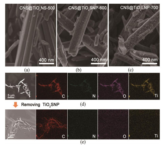
The morphologies of CNS@TiO2NS-500, CNS@TiO2SNP-600, and CNS@TiO2LNP-700 are shown in Fig. 4a~c, respectively. All of them maintain a regular slatted structure and mimic the morphology of the HTO template after carbonization. As shown in Fig. S3, C, N, O, and Ti elements are uniformly distributed in the CNS@TiO2NS-500. The element mapping results of CNS@TiO2SNP-600 display the uniform distribution of C, N, O, and Ti elements (Fig. 4d), which are consistent with the XRD results in Fig. 2a. TiO2 nanoparticles with larger size can be found in CNS@TiO2LNP-700 (Fig. 4c), and element mapping results display a uniform distribution of C, N, O, and Ti elements (Fig. S5). To further validate the CNS@TiO2NS-500, CNS@TiO2SNP-600, and CNS@TiO2LNP-700 with layered structures, carbon materials were retained by removing TiO2 (including anatase and rutile) between the layers via a simple wet chemical etching method. The element mapping images of carbon nanosheets (CNS-600) are shown in Fig. 4e. It is clear that the distribution of C element is in accordance with the SEM image of CNS-600. The element mapping and EDS results of CNS-500 and CNS-700 are shown in Fig. S6 and Fig. S7, respectively. Similarly, the element of C is in accordance with the SEM images of CNS-500 and CNS-700, respectively. These results indicate that TiO2 nanoparticles have been completely removed from the CNS@TiO2NS-500, CNS@TiO2SNP-600, and CNS@TiO2LNP-700. The morphologies of CNS@TiO2NS-500, CNS@TiO2SNP-600, and CNS@TiO2LNP-700 are shown in Fig. S8, the obtained carbon materials present sheet-like structure and stack together after removing TiO2, mimicing the morphology of the HTO template. The specific surface area of CNS-500, CNS-600, and CNS-700 is 152.6, 388.8, and 566.8 m2⋅g-1, respectively (Fig. S9).
The constant current charge-discharge tests of the coin cell with CNS@TiO2SNP-600 electrode at current density of 0.1~12.8 A⋅g-1 and voltage windows of 0.05~3 V are shown in Fig. 5a. The charge-discharge curve of CNS@TiO2SNP-600 exhibits a steep trend according with a typical capacitive energy storage[32, 33], which is similar to that of CNS@TiO2NS-500 (Fig. S10a) and CNS@TiO2LNP-700 (Fig. S11a). The discharge specific capacity at current density of 0.1, 0.2, 0.4, 0.8, 1.6, 3.2, 6.4, 9.6, and 12.8 A⋅g-1 is 430.4, 347.3, 301.4, 262.7, 224.9, 187.5, 147.8, 121.9, and 101.8 mAh⋅g-1, respectively (Fig. 5b). The discharge specific capacities of all three coins are higher than the theoretical specific capacity of TiO2, which is mainly ascribed to the special layered structure of carbon nanosheets and anatase TiO2 nanoparticles[20, 34, 35]. The discharge specific capacity of CNS@TiO2SNP-600 rapidly increases to 322.1 mAh⋅g-1 when the current density returns back to 0.2 A⋅g-1, which is higher than that of CNS@TiO2NS-500 and CNS@TiO2LNP-700. The CNS@TiO2SNP-600 displays a better rate performance than the other two electrodes. Meanwhile, the TiO2 nanosheets between the CNS layers in CNS@TiO2SNP-600 are in-situ transformed into anatase nanoparticles (16.9 nm). The small-sized nanoparticles generated by in-situ transformation can provide more interface contact with the interlayered CNS. And thus it contributes to an additional storage capacity of lithium ions[26]. However, the size of TiO2 particles in CNS@TiO2LNP-700 is larger than that in the CNS@TiO2SNP-600, which tends to reduce the effective contact area between the nanoparticles and the carbon nanosheets. Apparently, the TiO2 nanoparticles with a large size have limited the capacitance effect of CNS@TiO2LNP-700. Its discharge specific capacity is 328.2 mAh⋅g-1 at a current density of 0.1 A⋅g-1. Usually, the discharge specific capacity of materials is highly influenced by their conductivity[36, 37]. The conductivity of CNS@TiO2NS-500 (6.18 × 10⁻⁵ s⋅cm-1) is lower than that of CNS@TiO2LNP-700 (2.36 × 10⁻¹ s⋅cm-1). Therefore, the discharge specific capacity of CNS@TiO2NS-500 decreases significantly than that of CNS@TiO2LNP-700. The discharge specific capacity of CNS@TiO2NS-500 (23.2 mAh⋅g-1) is obviously lower than that of the CNS@TiO2LNP-700 (61.1 mAh⋅g-1) at a current density of 12.8 A⋅g-1. However, the conductivity of CNS@TiO2SNP-600 (1.90 × 10⁻² s⋅cm-1) is slightly lower than that of CNS@TiO2LNP-700 (2.36 × 10⁻¹ s⋅cm-1). The difference in conductivity does not lead to a significant difference in the electrochemical performance of CNS@TiO2SNP-600 and CNS@TiO2LNP-700 (Fig. 5b). Fig. 5c shows specific energy density and specific power density of the coin cells with the CNS@TiO2NS-500, CNS@TiO2SNP-600, and CNS@TiO2LNP-700. The coin cell with CNS@TiO2SNP-600 generates a specific energy density of 366.3 Wh⋅kg-1 and a specific power density of 84.2 W⋅kg-1 at 0.1 A⋅g-1. A specific energy density of 72.5 Wh⋅kg-1 and a specific power of 9.1 kW⋅kg-1 still remains at a high current density of 12.8 A⋅g-1. The CNS@TiO2SNP-600 exhibits higher specific energy density and specific power density than that of CNS@TiO2NS-500 and CNS@TiO2LNP-700.
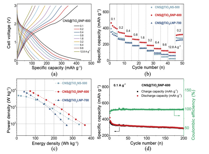
In addition to show ultra-high specific capacity and rate performance, CNS@TiO2SNP-600 also exhibits excellent cycling stability properties. Fig. 5d illustrates the cycle stability of the coin cell with CNS@TiO2NS-500, CNS@TiO2SNP-600, and CNS@TiO2LNP-700 electrode during the charge-discharge process in lithium-ion battery. The coin cell is charged and discharged for 200 cycles at a current density of 0.1 A⋅g-1 and at a voltage window of 0.05~3 V. The charge-discharge behavior of the first 6 cycles is the activation process of the material. A solid electrolyte interface (SEI) layer is easily formed on the surface of the active material during the charge-discharge process[38, 39]. Although the SEI layer can deplete both Li and electrolyte, the passivation layer can maintain the stability of the material. The specific discharge capacity of CNS@TiO2SNP-600 stabilizes at 354 mAh⋅g-1 after 6 cycles, which is ascribed to the inevitable formation of SEI layers. The specific discharge capacity is 312 mAh⋅g-1 after 100 cycles, and the relative capacity retention rate is 88.1%. After 200 cycles, the discharge specific capacity is 294 mAh⋅g-1 and the capacity retention still remains 83.1%, demonstrating a remarkable cycling stability for CNS@TiO2SNP-600.
The diffusion kinetics of lithium ions in CNS@TiO2NS-500, CNS@TiO2SNP-600, and CNS@TiO2LNP-700 electrodes were further investigated by cyclic voltammetry tests, as shown in Figs. 6 and S12. A pair of wide reduction-oxidation peaks appear in the voltage windows from 1.0 to 2.5 V as shown in Fig. 6a for CNS@TiO2SNP-600, which corresponds to the embedding of lithium ions in the crystal structure of TiO2. The quasi rectangular wave of CNS@TiO2SNP-600 is similar to that of the CNS@TiO2NS-500 (Fig. S10b) and CNS@TiO2LNP-700 (Fig. S11b), typical oxidation and reduction peaks appear at 2.10 and 1.70 V, 2.10 and 1.74 V, respectively. It demonstrates that the three electrodes possess the ability of capacitive energy storage[32, 40-43]. These results are in accordance with the exfoliation/embedding of lithium ions in TiO2[44, 45].
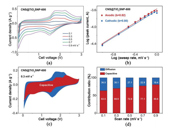
To further understand the mechanism of lithium storage, we have conducted a kinetic analysis according to the report by Dunn et. al[46]. The relationship between peak current (i) and scanning rates (v) is shown in the following formula: i = avb. Here, a and b are adjustable values. Based on the slope of log(i) – log(v), when the calculated value of b is close to 0.5 and 1.0, the corresponding current is mainly controlled by the diffusion and surface capacitance, respectively. b value of CNS@TiO2SNP-600 during the charge and discharge process is calculated to be 0.82 and 0.80, respectively (Fig. 6b), demonstrating that the capacitance current is dominant[47]. The redox reaction occurs on the surface of the small-sized TiO2 nanoparticles between the interlayers of the CNS@TiO2SNP-600, which can effectively reduce the excessive insertion energy storage occurring inside the interlayers due to the large sized TiO2 (Figs. S12a and S12b). In contrast, the large size of TiO2 nanoparticles in CNS@TiO2LNP-700 can prolong the distance of lithium ion transport and impede the diffusion kinetics (The b-value of CNS@TiO2SNP-600 nanosheet composites was significantly higher than that of CNS@TiO2LNP-700, as shown in Figs. S12b and 6b). In addition, a microscopic structure of electric double layer was found. Both the high conductivity of carbon nanosheets and the close contact between the layers and small-sized TiO2 nanoparticles contribute to a higher specific capacity than the theoretical specific capacity. The discharge specific capacity achieves to 101.8 mAh⋅g-1 at a high current density of 12.8 A⋅g-1. In comparison, an amount of redox reaction occurs on the surface of TiO2 between the interlayers of CNS@TiO2NS-500 and CNS@TiO2LNP-700 (Figs. S12a and S12b), but its rate performance was severely limited by the low electronic conductivity. The ratios of the pseudo-capacitance contribution of the three composites at different scan rates are calculated from the relationship of i = k1v + k2v1/2. Here, k1v and k2v1/2 denote the capacitance and diffusion currents, respectively. The pseudo-capacitive contribution for CNS@TiO2SNP-600 electrode is as high as 69.9% at a scan rate of 0.3 mV⋅s-1 (Fig. 6c). It can be seen that the diffusion-controlled currents mainly occur near the cathode/anode peaks, which are associated with the redox reaction of lithium ion insertion/de-insertion. The ratio of pseudo-capacitive storage capacity contribution increases gradually with the increasing scan rate and achieves to 80.6% at a scan rate of 0.9 mV⋅s-1 (Fig. 6d). The pseudo-capacitive contribution of CNS@TiO2NS-500 and CNS@TiO2 LNP-700 electrodes at different scan rates is shown in Figs. S12e and S12f, respectively.
The two-dimensional composite materials composed of TiO2 and carbon nanosheets was successfully synthesized via high-temperature polymerization and carbonization method by using the layered HTO as template. Specifically, benzylamine was embedded through the wedge effect to increase the interlayer distance, and then benzidine was inserted between the HTO layers as a carbon source through an exchange reaction. The morphology and size of TiO2 were easily influenced by the carbonization temperature. TiO2 nanosheets (TiO2NS), TiO2 small-sized nanoparticles (TiO2SNP), and TiO2 large-sized nanoparticles (TiO2LNP) inserted between the carbon nanosheets (CNS) were obtained under three different heat-treatment temperature of 500, 600, and 700 ℃, respectively. The CNS@TiO2SNP-600 displays a high specific discharge capacity of 430.4 mAh⋅g-1 at a current density of 0.1 A⋅g-1, and the capacity retention rate is 88.1% after 100 cycles. A high specific discharge capacity of 101.8 mAh⋅g-1 still remains at a high current density of 12.8 A⋅g-1. These results indicate the capacitance effect, originating from the close contact between CNS and TiO2SNP, can greatly increase the storage capacity of lithium ions; and the CNS grown in situ can improve the rate performance and cycle stability of TiO2. This kind of materials can be used in the lithium-ion batteries and in other related electrochemical storage and conversion devices.
Zhao, Y.; Wang, L. P.; Sougrati, M. T.; Feng, Z. X.; Leconte, Y.; Fisher, A.; Srinivasan, M.; Xu, Z. C. A review on design strategies for carbon based metal oxides and sulfides nanocomposites for high performance Li and Na ion battery anodes. Adv. Energy Mater. 2017, 7, 1601424−70. doi: 10.1002/aenm.201601424
Subramanian, V.; Karki, A.; Gnanasekar, K. I.; Eddy, F. P.; Rambabu, B. Nanocrystalline TiO2 (anatase) for Li-ion batteries. J. Power Sources 2006, 159, 186−192. doi: 10.1016/j.jpowsour.2006.04.027
An, G. H.; Ahn, H. J. Carbon nanofiber/cobalt oxide nanopyramid core-shell nanowires for high-performance lithium-ion batteries. J. Power Sources 2014, 272, 828−836. doi: 10.1016/j.jpowsour.2014.09.032
Cho, J. S.; Hong, Y. J.; Kang, Y. C. Design and synthesis of bubble-nanorod-structured Fe2O3-carbon nanofibers as advanced anode material for Li-ion batteries. ACS Nano 2015, 9, 4026−4035. doi: 10.1021/acsnano.5b00088
Yan, C. S.; Chen, G.; Zhou, X.; Sun, J. X.; Lv, C. Template-based engineering of carbon-doped Co3O4 hollow nanofibers as anode materials for lithium-ion batteries. Adv. Funct. Mater. 2016, 26, 1428−1436. doi: 10.1002/adfm.201504695
Wang, H. W.; Jia, G. C.; Guo, Y. Y.; Zhang, Y. Q.; Geng, H. B.; Xu, J.; Mai, W. J.; Yan, Q. Y.; Fan, H. J. Atomic layer deposition of amorphous TiO2 on carbon nanotube networks and their superior Li and Na ion storage properties. Adv. Mater. Interfaces 2016, 3, 1600375−9. doi: 10.1002/admi.201600375
Wang, X. Y.; Fan, L.; Gong, D. C.; Zhu, J.; Zhang, Q. F.; Lu, B. G. Core-shell Ge@Graphene@ TiO2 nanofibers as a high-capacity and cycle-stable anode for lithium and sodium ion battery. Adv. Funct. Mater. 2016, 26, 1104−1111. doi: 10.1002/adfm.201504589
Etacheri, V.; Yourey, J. E.; Bartlett, B. M. Chemically bonded TiO2-bronze nanosheet/reduced graphene oxide hybrid for high-power lithium ion batteries. ACS Nano 2014, 8, 1491−1499. doi: 10.1021/nn405534r
Hu, T.; Sun, X.; Sun, H. T.; Yu, M. P.; Lu, F. Y.; Liu, C. S.; Lian, J. Flexible free-standing graphene-TiO2 hybrid paper for use as lithium ion battery anode materials. Carbon 2013, 51, 322−326. doi: 10.1016/j.carbon.2012.08.059
Kim, H. K.; Mhamane, D.; Kim, M. S.; Roh, H. K.; Aravindan, V.; Madhavi, S.; Roh, K. C.; Kim, K. B. TiO2-reduced graphene oxide nanocomposites by microwave-assisted forced hydrolysis as excellent insertion anode for Li-ion battery and capacitor. J. Power Sources 2016, 327, 171−177. doi: 10.1016/j.jpowsour.2016.07.053
Li, W.; Wang, F.; Liu, Y. P.; Wang, J. X.; Yang, J. P.; Zhang, L. J.; Elzatahry, A. A.; Al-Dahyan, D.; Xia, Y. Y.; Zhao, D. Y. General strategy to synthesize uniform mesoporous TiO2/graphene/mesoporous TiO2 sandwich-like nanosheets for highly reversible lithium storage. Nano Lett. 2015, 15, 2186−2193. doi: 10.1021/acs.nanolett.5b00291
Mo, R. W.; Lei, Z. Y.; Sun, K. N.; Rooney, D. Facile synthesis of anatase TiO2 quantum-dot/graphene-nanosheet composites with enhanced electrochemical performance for lithium-ion batteries. Adv. Mater. 2014, 26, 2084−2088. doi: 10.1002/adma.201304338
Qiu, B. C.; Xing, M. Y.; Zhang, J. L. Mesoporous TiO2 nanocrystals grown in situ on graphene aerogels for high photocatalysis and lithium-ion batteries. J. Am. Chem. Soc. 2014, 136, 5852−5855. doi: 10.1021/ja500873u
Ren, G. F.; Hoque, M. N. F.; Liu, J. W.; Warzywoda, J.; Fan, Z. Y. Perpendicular edge oriented graphene foam supporting orthogonal TiO2 (B) nanosheets as freestanding electrode for lithium ion battery. J. Am. Chem. Soc. 2016, 21, 162−171.
Ren, Y.; Liu, Z.; Pourpoint, F.; Armstrong, A. R.; Grey, C. P.; Bruce, P. G. Nanoparticulate TiO2 (B): an anode for lithium-ion batteries. Angew. Chem. Int. Ed. 2012, 124, 2206−2209. doi: 10.1002/ange.201108300
Wang, D. H.; Choi, D.; Li, J.; Yang, Z. G.; Nie, Z. M.; Kou, R.; Hu, D. H.; Wang, C. M.; Saraf, L. V.; Zhang, J. G. Self-assembled TiO2-graphene hybrid nanostructures for enhanced Li-ion insertion. ACS Nano 2009, 3, 907−914. doi: 10.1021/nn900150y
Fu, W. W.; Li, Y. T.; Chen, M. S.; Hu, Y. J.; Liu, B. H.; Zhang, K.; Zhan, C. Y.; Zhang, M.; Shen, Z. R. An orderly arrangement of layered carbon nanosheet/TiO2 nanosheet stack with superior artificially interfacial lithium pseudocapacity. J. Power Sources 2020, 468, 228363−7. doi: 10.1016/j.jpowsour.2020.228363
Hu, Y. J.; Li, Y. T.; Cheng, J. F.; Chen, M. S.; Fu, W. W.; Liu, B. H.; Zhang, M.; Shen, Z. R. Intercalation of carbon nanosheet into layered TiO2 grain for highly interfacial lithium storage. ACS Appl. Mater. Inter. 2020, 12, 21709−21719. doi: 10.1021/acsami.0c03775
Li, Y. T.; Chen, M. S.; Cheng, J. F.; Fu, W. W.; Hu, Y. J.; Liu, B. H.; Zhang, M.; Shen, Z. R. Two-dimensional layered ultrathin carbon/TiO2 nanosheet composites for superior pseudocapacitive lithium storage. Langmuir 2020, 36, 2255−2263. doi: 10.1021/acs.langmuir.9b03889
Brezesinski, T.; Wang, J.; Polleux, J.; Dunn, B.; Tolbert, S. H. Templated nanocrystal-based porous TiO2 films for next-generation electrochemical capacitors. J. Am. Chem. Soc. 2009, 131, 1802−1809. doi: 10.1021/ja8057309
Mirhashemihaghighi, S.; León, B.; Pére Vicente, C.; Tirado, J. L.; Stoyanova, R.; Yoncheva, M.; Zhecheva, E.; Sáez Puche, R.; Arroyo, E. M.; Romero de Paz, J. Lithium storage mechanisms and effect of partial cobalt substitution in manganese carbonate electrodes. Inorg. Chem. 2012, 51, 5554−5560. doi: 10.1021/ic3004382
Sasaki, T.; Kooli, F.; Iida, M.; Michiue, Y.; Takenouchi, S.; Yajima, Y.; Izumi, F.; Chakoumakos, B. C.; Watanabe, M. A mixed alkali metal titanate with the lepidocrocite-like layered structure. Preparation, crystal structure, protonic form, and acid-base intercalation properties. Chem. Mater. 1998, 10, 4123−4128. doi: 10.1021/cm980535f
Ding, W.; Wei, Z. D.; Chen, S. G.; Qi, X. Q.; Yang, T.; Hu, J. S.; Wang, D.; Wan, L. J.; Alvi, S. F.; Li, L. Space-confinement-induced synthesis of pyridinic- and pyrrolic-nitrogen-doped graphene for the catalysis of oxygen reduction. Angew. Chem. Int. Ed. 2013, 125, 11971−11975. doi: 10.1002/ange.201303924
Akalin, E.; Akyüz, S. Structure and vibrational spectra of benzidine. J. Mol. Struct. 2003, 651, 571−577.
Akyüz, S.; Bulat, T.; Özel, A. E.; Basar, G. FT-IR and laser Raman spectroscopic investigation of transition metal halide complexes of benzidine. Vib. Spectrosc 1997, 14, 151−154. doi: 10.1016/S0924-2031(96)00070-7
Wang, J.; Polleux, J.; Lim, J.; Dunn, B. Pseudocapacitive contributions to electrochemical energy storage in TiO2 (anatase) nanoparticles. J. Phys. Chem. C 2007, 111, 14925−14931. doi: 10.1021/jp074464w
Yang, Z. G.; Choi, D.; Kerisit, S.; Rosso, K. M.; Wang, D. H.; Zhang, J.; Graff, G.; Liu, J. Nanostructures and lithium electrochemical reactivity of lithium titanites and titanium oxides: a review. J. Power Sources 2009, 192, 588−598. doi: 10.1016/j.jpowsour.2009.02.038
Wu, Q. L.; Xu, J. G.; Yang, X. F.; Lu, F. Q.; He, S. M.; Yang, J. L.; Fan, H. J.; Wu, M. M. Ultrathin anatase TiO2 nanosheets embedded with TiO2-B nanodomains for lithium-ion storage: capacity enhancement by phase boundaries. Adv. Energy Mater. 2015, 5, 1401756−9. doi: 10.1002/aenm.201401756
Liu, G. Y.; Zhao, Y. Y.; Tang, Y. F.; Liu, X. D.; Liu, M.; Wu, P. J. In situ sol-gel synthesis of Ti2Nb10O29/C nanoparticles with enhanced pseudocapacitive contribution for a high-rate lithium-ion battery. Rare Metals 2020, 39, 1063−1071. doi: 10.1007/s12598-020-01462-w
Luo, R.; Ma, Y. T.; Qu, W. J.; Qian, J.; Li, L.; Wu, F.; Chen, R. J. High pseudocapacitance boosts ultrafast, high-capacity sodium storage of 3D graphene foam encapsulated TiO2 architecture. ACS Appl. Mater. Inter. 2020, 12, 23939−23950. doi: 10.1021/acsami.0c04481
Wang, Y. X.; Yang, J. P.; Chou, S. L.; Liu, H. K.; Zhang, W. X.; Zhao, D. Y.; Dou, S. X. Uniform yolk-shell iron sulfide-carbon nanospheres for superior sodium-iron sulfide batteries. Nat. Commun. 2015, 6, 1−9.
Augustyn, V.; Come, J.; Lowe, M. A.; Kim, J. W.; Taberna, P. L.; Tolbert, S. H.; Abruña, H. D.; Simon, P.; Dunn, B. High-rate electrochemical energy storage through Li+ intercalation pseudocapacitance. Nat Mater. 2013, 12, 518−522. doi: 10.1038/nmat3601
Augustyn, V.; Simon, P.; Dunn, B. Pseudocapacitive oxide materials for high-rate electrochemical energy storage. Energy Environ. Sci. 2014, 7, 1597−1614. doi: 10.1039/c3ee44164d
Li, D. D.; Zhang, L.; Chen, H. B.; Wang, J.; Ding, L. X.; Wang, S. Q.; Ashman, P. J.; Wang, H. H. Graphene-based nitrogen-doped carbon sandwich nanosheets: a new capacitive process controlled anode material for high-performance sodium-ion batteries. J. Mater. Chem. A 2016, 4, 8630−8635. doi: 10.1039/C6TA02139E
Li, S.; Qiu, J. X.; Lai, C.; Ling, M.; Zhao, H. J.; Zhang, S. Q. Surface capacitive contributions: towards high rate anode materials for sodium ion batteries. Nano Energy 2015, 12, 224−230. doi: 10.1016/j.nanoen.2014.12.032
Zhang, M.; Hu, Y. J.; Cheng, J. F.; Fu, W. W.; Shen, Z. R. Synthesis of highly-ordered two-dimensional hierarchically porous carbon nanosheet stacks as advanced electrode materials for lithium-ion storage. ACS Appl. Energy Mater. 2020, 4, 226−232.
Chen, Y. N.; Fu, K.; Zhu, S. Z.; Luo, W.; Wang, Y. B.; Li, Y. J.; Hitz, E.; Yao, Y. G.; Dai, J. Q.; Wan, J. Y.; Danner, V. A.; Li, T.; Hu, L. B. Reduced graphene oxide films with ultrahigh conductivity as Li-ion battery current collectors. Nano Lett. 2016, 16, 3616−3623. doi: 10.1021/acs.nanolett.6b00743
Ventosa, E.; Madej, E.; Zampardi, G.; Mei, B.; Weide, P.; Antoni, H.; Mantia, F. L.; Muhler, M.; Schuhmann, W. Solid electrolyte interphase (SEI) at TiO2 electrodes in Li-ion batteries: defining apparent and effective SEI based on evidence from X-ray photoemission spectroscopy and scanning electrochemical microscopy. ACS Appl. Mater. Inter. 2017, 9, 3123−3130. doi: 10.1021/acsami.6b13306
Ren, H.; Yu, R. B.; Qi, J.; Zhang, L. J.; Jin, Q.; Wang, D. Hollow multishelled heterostructured anatase/TiO2 (B) with superior rate capability and cycling performance. Adv. Mater. 2019, 31, 1805754−7. doi: 10.1002/adma.201805754
Hao, B.; Yan, Y.; Wang, X. B.; Chen, G. Synthesis of anatase TiO2 nanosheets with enhanced pseudocapacitive contribution for fast lithium storage. ACS Appl. Mater. Inter. 2013, 5, 6285−6291. doi: 10.1021/am4013215
Lou, S. F.; Zhao, Y.; Wang, J. J.; Yin, G. P.; Du, C. Y.; Sun, X. L. Ti-based oxide anode materials for advanced electrochemical energy storage: lithium/sodium ion batteries and hybrid pseudocapacitors. Small 2019, 15, 1904740−44. doi: 10.1002/smll.201904740
Muller, G. A.; Cook, J. B.; Kim, H. S.; Tolbert, S. H.; Dunn, B. High performance pseudocapacitor based on 2D layered metal chalcogenide nanocrystals. Nano Lett. 2015, 15, 1911−1917. doi: 10.1021/nl504764m
Que, L. F.; Yu, F. D.; Wang, Z. B.; Gu, D. M. Pseudocapacitance of TiO2-x/CNT anodes for high-performance quasi-solid-state Li-ion and Na-ion capacitors. Small 2018, 14, 1704508−9. doi: 10.1002/smll.201704508
Wei, H.; Rodriguez, E. F.; Hollenkamp, A. F.; Bhatt, A. I.; Chen, D. H.; Caruso, R. A. High reversible pseudocapacity in mesoporous yolk-shell anatase TiO2/TiO2 (B) microspheres used as anodes for Li-ion batteries. Adv. Funct. Mater. 2017, 27, 1703270−9. doi: 10.1002/adfm.201703270
Xing, Y. L.; Wang, S. B.; Fang, B. Z.; Song, G.; Wilkinson, D. P.; Zhang, S. C. N-doped hollow urchin-like anatase TiO2@C composite as a novel anode for Li-ion batteries. J. Power Sources 2018, 385, 10−17. doi: 10.1016/j.jpowsour.2018.02.077
Augustyn, V.; Come, J.; Lowe, M. A.; Kim, J. W.; Taberna, P.; Tolbert, S. H.; Abruña, H. D.; Simon, P.; Dunn, B. High-rate electrochemical energy storage through Li+ intercalation pseudocapacitance. Nat. Mater. 2013, 12, 518−522. doi: 10.1038/nmat3601
Jiang, J. M.; Zhang, Y. D.; An, Y. F.; Wu, L. Y.; Zhu, Q.; Dou, H.; Zhang, X. G. Engineering ultrathin MoS2 nanosheets anchored on N-Doped carbon microspheres with pseudocapacitive properties for high-performance lithium-ion capacitors. Small. Methods 2019, 7, 1900081−10.

Figure 2 (a) XRD, (b) FT-IR of the HTO, benzylamine/TiO2, benzidine/TiO2, polybenzidine/TiO2, CNS@TiO2NS-500, CNS@TiO2SNP-600, and CNS@TiO2LNP-700

Figure 3 (a) TG survey, (b) Raman spectra, (c) N2 adsorption-desorption isotherms, and (d) pore size distribution of the CNS@TiO2NS-500, CNS@TiO2SNP-600, and CNS@TiO2LNP-700

Figure 4 SEM of (a) CNS@TiO2NS-500, (b) CNS@TiO2SNP-600, and (c) CNS@TiO2LNP-700; (d) SEM and elemental mapping of CNS@TiO2SNP-600; (e) SEM and elemental mapping of the CNS-600 after removing TiO2 from the CNS@TiO2SNP-600

Figure 5 (a) Representative galvanostatic discharge/charge profiles at various current densities of CNS@TiO2SNP-600; (b) Comparison of the rate capability of the CNS@TiO2NS-500, CNS@TiO2SNP-600, and CNS@TiO2LNP-700; (c) Ragone plot of coin cells with CNS@TiO2NS-500, CNS@TiO2SNP-600, and CNS@TiO2LNP-700; (d) Cycling performance of the coin cell with CNS@TiO2SNP-600 at 0.1 A⋅g-1

Figure 6 (a) Cyclic voltammetric curve of CNS@TiO2SNP-600. (b) b-value calculated by the relationship between the scan rate and the peak current. (c) Segregation of capacitive and diffusion-controlled currents in CNS@TiO2SNP-600 at a scan rate of 0.3 mV⋅s-1. (d) Contribution ratio of capacitance and diffusion-controlled current at various scan rates
Table 1. Interlayer Distance Calculated from (010) Diffraction Peak from XRD Data
| Sample | HTO | Benzylamine/TiO2 | Benzidine/TiO2 | Polybenzidine/TiO2 |
| 2 Theta (°) | 9.96 | 4.82 | 5.01 | 7.24 |
| Interlayer distance (Å) | 8.9 | 18.4 | 17.8 | 12.2 |
 下载: 导出CSV

 扫一扫看文章

扫一扫关注我们

 下载:
下载: