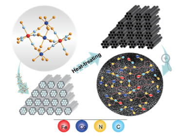
图 1.
Schematic illustration of the preparation of Fe-Co-N-GC

The synergistic effect of the multi-heteroatoms doped into the carbon nanomaterials can distinctly enhance the catalytic performance of the carbon-based electrocatalysts for oxygen reduction reaction (ORR) [1] and has been recognized as a viable strategy for developing highly efficient non-precious metal catalyst to replace Pt-based electrocatalyst in the clean energy and energy-efficient devices such as polymer electrolyte membrane fuel cell (PEMFC).
Among the non-precious metal carbon-based catalysts reported for ORR, Fe-N- C and Co -N-C catalysts have been recognized as one of the most promising candidates for replacing platinum -based catalysts to catalyze ORR[2-4]. On the other hand, it has been found that Fe -N-C catalysts have higher ORR activity than Co-N-C catalysts, but the latter possessed higher catalytic stability[5-6]. To combine the advantages of high electrochemical stability and ORR activity, bimetallic catalysts using Fe and Co as the metal sources have been investigated, such as binary Fe/Co- TPTZ[7], FeCo-OMPC[8], and Fe/Co - NpGr[9]. All these studies indicated that the bimetallic catalysts possess enhanced electrochemical activity and stability towards ORR compared to the catalysts containing single metal, owing to the synergistic effect between Fe and Co active species.
The bimetallic N-containing catalysts are usually prepared by two kinds of methods. One is directly pyrolyzing the mixture of transition metal-containing macrocycles[7, 10], or the mixture of transition-metal inorganic salts and nitrogen-containing organic compounds[11-13]. The other is by nano-casting of ordered mesoporous silica with the mixture of metal - containing macrocycles[14]. However, the distribution of Fe—N and Co—N active sites in the catalysts prepared by these methods is uncontrollable and causes uneven load. The confirmation for the structural character of the active sites and mutual contact pattern between Co and Fe atoms is very difficult or impossible because the bonding behavior of Co and Fe atoms in the pyrolysis products has the features of randomness as well as varieties.
In this work, an efficient ordered mesoporous Fe- Co-N -doped graphite-based catalyst (Fe-Co-N-GC) has been successfully prepared by using a water-soluble Fe- Co bimetallic coordination compound as precursors and ordered mesoporous silica SBA - 15 as a template (Fig. 1). In the synthesis, the special molecule structure of the precursor can facilitate the formation of homogeneous and concentrated active centers and provide the building block of active sites, which may enhance the synergistic effect of the different components and improve electrochemical stability and the catalytic activity of the prepared Fe-Co-based catalyst. As a result, the catalytic activity and stability of Fe-Co-N-GC were demonstrated to outperform the commercial Pt/C catalyst.
Typical, Pluronic P123 triblock copolymer (Mw= 5 800, Aldrich, 4.0 g) was added in the solution containing deionized water (144 g) and HCl (160 mL, 1.6 mol·L-1), and allowed to stir at 40 ℃. Once the solution became clear, tetraethyl orthosilicate (TEOS, Aldrich, 8.3 g) was added in and kept being stirred at the same temperature for 24 h. Afterward, the obtained mixtures were transferred to a Teflon-lined autoclave, sealed, and heated at 150 ℃ for 24 h in an oven. The resulting white product was filtered, washed with deionized water, and dried at 100 ℃. Finally, mesoporous silica SBA - 15 was obtained by calcining the dried white product at 550 ℃ in the air for 4 h, with a heating rate of 1 ℃·min-1.
The crystal of {[Co(bpy)2]3[Fe(CN)6]2} [Fe(CN)6]1/3 was prepared according to the previously reported method[15] and used as the precursor. The filled-SBA-15 hard templates were achieved by alternate dipping and drying wet-filling techniques. In a typical procedure, 1.0 g of {[Co(bpy)2]3[Fe(CN)6]2} [Fe(CN)6 ] 1/3 was added in 200 mL of deionized water and stirred for 1 h at 70 ℃ to form a homogeneous solution. Then the solution was added into SBA-15 (0.5 g) drop by drop while the mixtures were ground in mortar under an infrared lamp to evaporate the solvent. The obtained products were heat-treated at different temperatures ranging from 600 to 800 ℃ under nitrogen flow with a ramping rate of 2 ℃·min-1 for 4 h. The Fe- Co-N-doped mesoporous material was obtained by etching the silica templates in HF (5%) solution. The synthesized materials were designated as Fe-Co-N-GC-600, Fe- Co-N-GC-700, and Fe- Co- N- GC- 800 according to the heattreatment temperatures.
The electrochemical activities of the catalysts for ORR were performed at room temperature by using a CHI- 760C electrochemical analyzer with a three-electrode cell system. A glassy carbon disk electrode (5 mm in diameter, Pine Instrument Co., USA) coated with as-synthesized Fe- Co- N- GC was employed as a working electrode, whereas an Ag/AgCl (KCl, 3 mol· L-1) and Pt electrode were used as reference and counter electrode in the measurement, respectively. For the preparation of the working electrode, the catalyst inks were prepared by dispersing 10 mg Fe-Co-N-GC or Pt/C catalyst (Johnson Matthey, 20% Pt) in a mixture of 1.25 mL of ethanol and 0.03 mL of Nafion (5%), then the desired amount of such catalyst inks was deposited onto the polished glassy carbon electrode and dried at room temperature before measurement.
Cyclic voltammetry (CV) and rotating disk electrode (RDE) techniques for ORR were carried out in an O2-saturated 0.1 mol·L-1 KOH solution. The loadings of the catalysts on the working electrode were 0.36 and 0.60 mg·cm-2 in O2-saturated 0.1 mol·L-1 KOH, respectively. The loadings of Pt/C (20%) catalysts on the working electrode were 0.10 mg·cm-2 in both electrolytes. For all the CV, linear sweep voltammetry (LSV), and chronoamperometric measurements, the scan rate was 10 mV·s-1. All potentials in this study were reported concerning the reversible hydrogen electrode (RHE).
The onset ORR potential reported in this work was defined when ORR current density was 3 μA·cm-2 in RDE polarization curves[16-17]. The number (n) of electrons transferred during ORR was calculated by Koutecky-Levich (K-L) equations:
|
|
|
|
|
|
Where J represents the measured current density on the glassy carbon disk, JL is the diffusion - limited current density, JK is the kinetic current density, ω is the angular velocity of the disk, B could be calculated from the slope of K-L plots, F is the Faraday constant (F=96 485 C·mol-1), k is the electron transfer rate constant, v is the kinematic viscosity of the electrolyte, c0 is the bulk concentration of O2 and D0 is diffusion coefficient of O2.
X-ray diffraction patterns (XRD) were recorded on a D8 advance diffractometer (Bruker, Germany) attached with a Cu Kα (λ=0.154 05 nm) as a radiation source, a tube voltage of 40 kV, a tube current of 40 mA, and a scanning range of 0° -140°. Scanning electron microscopy (SEM) images were taken using ST-4800 (Hitachi) scanning electron microscopes operated at an accelerating voltage of 10 kV. Transmission electron microscopy (TEM) images, high-resolution TEM (HRTEM) images, selected area electron diffraction (SAED) patterns, scanning transmission electron microscopy (STEM), and energy-dispersive X-ray spectroscopy (EDS) line scan data were conducted on a JEM-2010 transmission electron microscope (JEOL, Japan) at an acceleration voltage of 200 kV. Nitrogen adsorption-desorption isotherms were performed on a Micromeritics ASAP 2020 analyzer at 77 K. The specific surface area was calculated by using the adsorption data via the Brunauer-Emmett-Teller (BET) method. The pore size distribution and the total pore volume were derived from the related adsorption branch by using the Barrett-Joyner-Halenda (BJH) model. FT-IR spectra were recorded with an infrared spectrophotometer (Bruker Tensor 27) using KBr pellets in a range of 400-4 000 cm-1. X-ray photoelectron spectroscopy (XPS) experiments were recorded on Axis Ultra DLD system using Al Kα radiation (1 486.6 eV). The XPS spectrum of the C peak was calibrated to 284.6 eV.
As mentioned, the non-precious metal carbonbased catalysts with excellent catalytic activity for ORR could be prepared by doping with multi-heteroatoms and the heat-treatment methods. However, it is still a long way off from the practical application. Further improvement of the catalytic performance requires insight into the component, structural feature, morphology, and the surroundings of the active sites in the catalysts. At the same time, these are also the necessary prerequisite and foundation to design and fabricate surface species with well-defined composition and structure and the desired functions. Based on such consideration, bimetallic coordination compound {[Co(bpy) 2]3[Fe(CN)6]2} [Fe(CN)6]1/3 was chosen as a precursor of the carbon - based catalysts. In the molecule structures, Co and Fe in a molar ratio of 9∶7 directly connect with N and C atoms, respectively, and are linked together by chain-link C≡N as shown in Fig. 1.
Some research results have illustrated that Fe(Co)—N(C) moieties were the highly active sites for ORR[18-21]. Fe—C≡N—Co moieties contained two kinds of active sites (Fe—C and Co—N) (Fig. 1), which were linked together by carbon-nitrogen triple bonds. Such structural features would be very helpful for investigating the synergistic effect of different active sites in the catalysts and creating highly efficient catalysts. To implant Fe—C≡N—Co moieties into the carbon-based materials, the confinement effect of the mesopore channels in the SBA-15 hard template is utilized to control the carbonization of {[Co(bpy)2]3 [Fe(CN)6]2} [Fe(CN)6]1/3 and limit the aggregation of the nanoparticles produced during the heating-treatment process (Fig. 1). By this synthesis strategy, the multiple components of carbon - based materials (Fe-Co-N-GC) were obtained and effectively realized the integration of multi-model active sites and the mesopores, which has promising application in the field of electrocatalysis.
The chemical compositions of the prepared samples were evaluated by XPS analysis and their contents are shown in Table 1. For Fe-Co-N-GC-700, the content (atomic fraction) of N (8.96%), Fe (0.67%), Co (0.86%) was relatively higher than others. In the Fe2p spectra in Fig. 2a, three peaks at 711.2, 724.3, and 717.7 eV are ascribed to the 2p3/2 and 2p1/2 of Fe in the Fe—N(C)x moieties and the satellite peak respectively[22-23]. Similarly, three peaks at 780.6, 796.2, and 785.4 eV in Co2p spectra (Fig. 2b) can be assigned to 2p3/2, 2p1/2 of Co in the Co — (C)Nx moieties and shakeup satellite peak[24-25]. It is important to note that no metallic iron or cobalt has been found by the XPS analysis.
 下载:
导出CSV
下载:
导出CSV
| Sample | Atomic fraction of the element / % | Mass fraction of the surface moiety / % | ||||||||||
| C | N | O | Fe | Co | Pyridinic-N | Pyrrolic-N | Graphitic-N | C≡N | Metallic-N | Pyridine N—O | ||
| Fe-Co-N-GC-600 | 78.91 | 9.03 | 10.15 | 0.68 | 0.87 | 31.91 | 25.10 | 23.90 | 5.08 | 3.96 | 10.05 | |
| Fe-Co-N-GC-700 | 80.47 | 8.96 | 9.04 | 0.67 | 0.86 | 27.41 | 22.77 | 26.22 | 4.15 | 10.02 | 9.43 | |
| Fe-Co-N-GC-800 | 85.95 | 5.13 | 8.23 | 0.37 | 0.48 | 23.19 | 10.02 | 48.94 | 4.05 | 5.29 | 8.51 | |
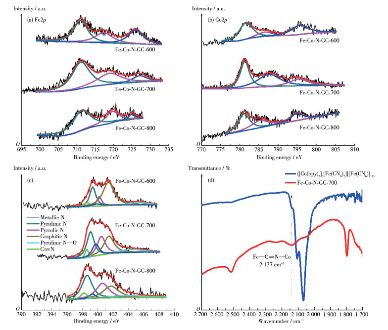
In the high -resolution N1s spectra (Fig. 2c), the six de-convoluted peaks at around 398.2, 398.4, 399.3, 399.9, 401.1, and 404.3 eV can be attributed to C≡N, pyridinic-N, pyrrolic-N, metallic - N, graphitic - N, and pyridine N—O, respectively[26-27], which indicate that Fe— Nx, Co—Nx, and Fe—C≡N—Co moieties may exist in the catalysts. The surface composition of different types of nitrogen estimated from the XPS analyses can be seen in Table 1. The relative amount of metallic-N species increases in the following order: Fe-Co-N-GC -600 (3.96%) < Fe-Co-N-GC-800(5.29%) < Fe-Co-N- GC-700 (10.02%). This variation tendency can be ascribed to the balance of old bonds (C—N) break, the formation of new ones (Fe—N, Co—N), and the degradation of Fe(Co)—Nx species. To further prove the existence of Fe—C≡N—Co moieties in the prepared materials, the FT -IR spectrum of Fe -Co -N -GC-700 was measured and shown in Fig. 2d. An absorption band corresponding to the stretching vibration of Fe—C≡ N—Co species was observed at 2 137 cm-1 in the spectra[15]. The experimental fact testifies that Fe—C≡ N—Co moiety has been successfully introduced into the Fe-Co-N-GC nanostructures. This remarkable feature in Fe-Co-N-GC-700 differs from the others and is unprecedented in the N-doped carbon-based materials containing Fe and Co.
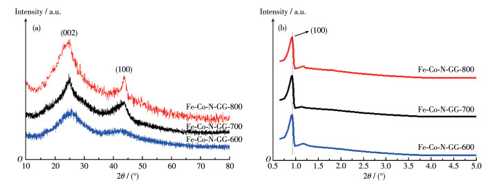
The morphology and crystal structure of the catalysts were characterized by XRD, TEM, and N2 adsorption-desorption analyses. The peaks with the higher intensity at 2θ=25° and 43° in Fig. 3a indicate that the carbons in pore-walls have higher graphitization degrees[28]. The intensity of these two peaks increases at higher heat-treatment temperatures, suggesting a higher graphitization degree of the catalyst frameworks. The low-angle X-ray diffraction of the catalysts in Fig. 3b shows a remarkable diffraction peak at about 0.9° (2θ), which can be indexed to the (100) plane of hexagonal structures.
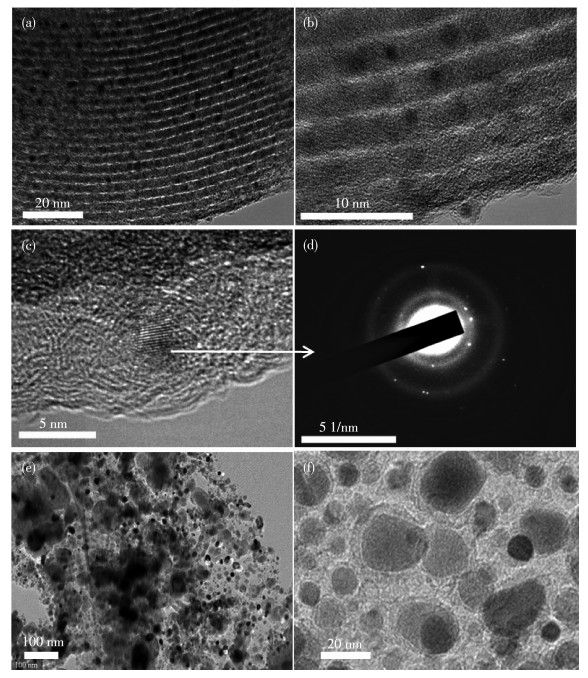
From the low-magnification TEM images in Fig. 4a and 4b, ordered 2D hexagonal mesostructures with rodlike morphology were observed. These results certify that the prepared materials are well-reverse replicas of the SBA-15 hard template[29].
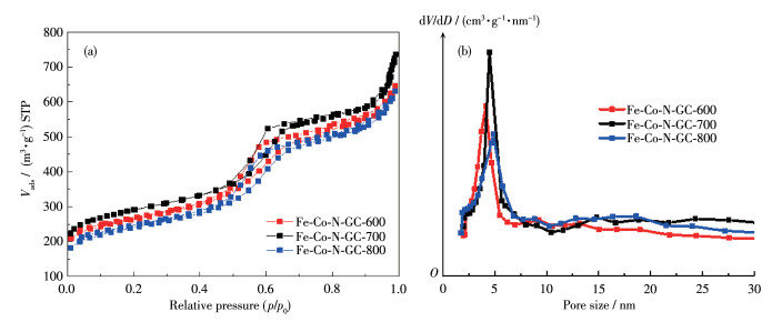
N2 -adsorption and desorption isotherms of Fe-Co- N-GC showed type Ⅳ isotherm and an H2-type hysteresis loop, indicating the uniform mesoporous structure (Fig. 5a) [30]. A very narrow pore-size distribution was obtained by calculation from the adsorption branch based on the BJH model (Fig. 5b). The detailed surface parameters are summarized in Table 2. Compared to the prepared materials at different temperatures, Fe-Co- N-GC-700 had a higher BET surface area (1 017 m2· g-1) than the others, which may be ascribed to the optimized structure of carbon framework and micropores at this heat-treating temperature. Mesopore sizes were found to increase (from 4.1 to 4.7 nm) due to the shrinkage of the pore walls while the heat-treatment temperature was from 600 to 800 ℃[31]. An optimization between BET surface and pore structure will be a benefit for more active sites exposed to the reactants and rapid transportation of O2 for ORR.
 下载:
导出CSV
下载:
导出CSV
| Sample | Surface area / (m2·g-1) | Pore size /nm | Pore volume / (cm3·g-1) |
| Fe-Co-N-GC-600 | 984 | 4.1 | 1.10 |
| Fe-Co-N-GC-700 | 1 017 | 4.5 | 1.19 |
| Fe-Co-N-GC-800 | 867 | 4.7 | 1.04 |
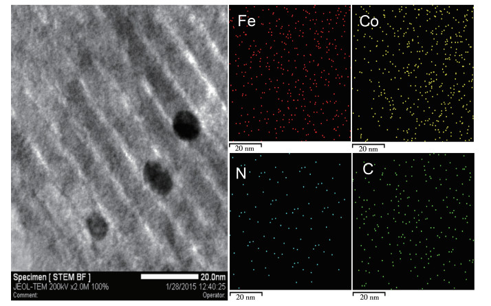
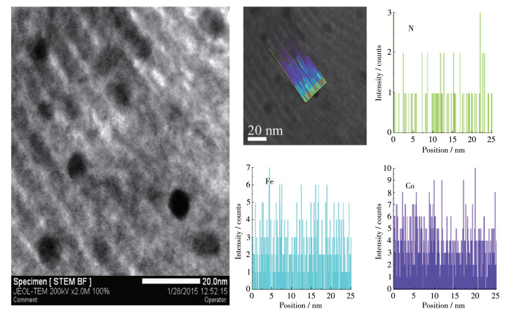
Moreover, an interesting phenomenon is shown in Fig. 4a and 4b was that some small nanoparticles were embedded in the surface of mesoporous frameworks in the prepared materials. For characterizing these nanoparticles, their microstructure, and chemical component and appearance had been investigated by HRTEM images (Fig. 4c), TEM-EDS mapping (Fig. 6)for Fe, Co and N elements, line-scanning EDS analysis (Fig. 7) by using scanning-mode TEM, and the SAED analysis (Fig. 4d). The EDS mapping images revealed that Fe, Co, and N atoms were well dispersed both on the surface of the carbon frame and carbon nanoparticles. Fig. 7 further attested that the distribution of Fe, Co, and N atoms in the nanoparticles was the same as that in the mesoporous framework. The graphitic lattice fringes could be distinctly observed in the HRTEM images of the nanoparticles in Fig. 4c. The corresponding SAED patterns in Fig. 4d for Fe-Co-N-GC-700 showed clear diffraction rings and dots, which exhibited a higher degree of graphitization in the nanoparticles. These facts above sufficiently verified that the nanoparticles and mesoporous frameworks of Fe-Co-N- GC-700 possessed the same component but a different degree of graphitization. To compare the superiority of the application of the hard template, a catalyst prepared without using the SBA -15 template was also presented. TEM images (Fig. 4e and 4f) showed agglomeration of carbon - coated nanoparticles, which mainly formed intra-particle pores.
The electrocatalytic activities of the prepared materials for ORR were studied by CVs and LSV measurements in O2-saturated 0.1 mol·L-1 KOH electrolyte. From the obtained results (Fig. 8a and 8b), it is seen that the catalyst prepared at 700 ℃ exhibited the highest peak-potential, half-wave potential (E1/2), and current density among the three prepared samples. This result testifies that 700 ℃ was identified as the optimum annealing temperature. This excellent catalytic performance of Fe-Co-N-GC-700 is mainly attributed to the higher density of activity centers and the highest surface area among these prepared materials. The voltammograms of Fe-Co-N-GC-700 with the loading of 0.36 mg·cm-2 revealed an obvious ORR peak at 0.90 V in alkaline medium saturated with O2, which was 20 mV higher than that of Pt/C catalyst (0.88 V) with mass loading of 0.1 mg·cm-2 (Fig. 8a). Under the same conditions, the kinetics aspects of the ORR activity of Fe-Co-N-GC -700 were investigated by LSV using the RDE method at an electrode rotation rate of 1 600 r· min-1 and the results are shown in Fig. 8b. The polarization curve of Fe- Co- N- GC- 700 displayed an onset potential of 1.07 V and a half-wave potential of 0.88 V and a current density of 5.6 mA·cm-2, which was 80 mV, 30 mV and 0.4 mA·cm-2 higher than those over the commercial Pt/C (Fig. 8b). These results indicated that the catalytic performance of Fe-Co-N-GC-700 was superior to that of Pt/C catalysts in 0.1 mol·L-1 KOH. Following the relationship between catalytic performance and structure of the materials, this super advantage of Fe-Co-N-GC-700 should undoubtedly ascribe to the special Fe— C≡N— Co moieties containing the bimetallic active site. It illustrates that the C≡N between Co and Fe can distinctly enhance the synergistic effect of Co and Fe and creates a novel high activity site. We also compared the ORR performance of catalyst prepared without using the SBA-15 template, as shown in Fig. 8a and 8b, the catalyst heat-treated at 700 ℃ exhibited the lowest peak - potential (0.82 V), half-wave potential (0.81 V), and current density (4.6 mA·cm-2) among the three prepared samples. It illustrates that intra-particle pores instead of ordered mesoporous structure prevent active sites exposure to the reactants and rapid transportation of O2 for ORR.

All these measurements are performed in O2-saturated 0.1 mol·L-1 KOH solution
For understanding the ORR kinetic process on Fe-Co-N-GC-700, polarization curves for ORR on Fe-Co-N-GC-700 electrode at various rotation speeds (between 400 and 2 500 r·min-1) were recorded with a scan rate of 10 mV·s-1 in alkaline medium (Fig. 8c). A diffusion-limited kinetic process over Fe-Co-N-GC-700 in 0.1 mol·L-1 KOH electrolytes (Fig. 8d) exhibited good linearity between 0.15 and 0.65 V, suggesting that the electron transfer numbers are consistent over different potentials. The electron transfer number in ORR was calculated to be 4.0 according to the K-L equations at 0.55 V (B=0.62nFc0D02/3v-1/6, c0=1.18×10⁻³ mol·L-1, D0=1.9×10⁻⁵ cm·s-1, v=0.089 3 cm2 ·s-1) [32], suggesting the ORR kinetic process on Fe-Co-N-GC follow a direct four-electron route.
The electrocatalytic methanol crossover property and durability of Fe-Co-N-GC-700 were investigated by chronoamperometric measurements. There was no significant decrease in the ORR current density over Fe- Co-N -GC-700 (Fig. 8e) after the injection of methanol (wMeOH=2%). But after the injection of methanol, a significant current decrease in the ORR activity of the commercial Pt/C catalyst was observed, indicating the occurrence of methanol oxidation reaction[33]. The experimental result demonstrates that Fe-Co-N-GC-700 has considerably better tolerance to methanol crossover than does Pt/C catalyst.
The long-term stability of the electrocatalytic activity for ORR over Fe-Co-N-GC-700 was measured. From the chronoamperometry, it was seen that the current density of Fe-Co-N- GC-700 showed insignificant decay of about 2.7% after running for 10 000 s. In contrast, as shown in Fig. 8f, the ORR current on Pt/C catalyst suffered from a 16.0% loss after running for 10 000 s. Fe-Co-N-GC-700 exhibited excellent stability compared to the commercial Pt/C catalyst.
In summary, Fe-Co-N -doped mesoporous graphite catalyst (Fe-Co-N-GC) can be successfully prepared by using the water-soluble Fe-Co bimetallic coordination compound {[Co(bpy)2]3[Fe(CN) 6 ] 2}[Fe(CN)6] 1/3 as precursors and ordered mesoporous silica SBA-15 as templates. The ORR onset potential, half-wave potential, and current density over Fe-Co-N-GC- 700 prepared at a heat-treatment temperature of 700 ℃ reached 1.07 V, 0.88 V, and 5.6 mA·cm-2, which were 80 mV, 30 mV, and 0.4 mA·cm-2 higher than those over Pt/C catalyst, respectively. The investigation results indicate that such super advantage of Fe-Co-N-GC-700 should ascribe to the special Fe—C≡N—Co activity site. Moreover, Fe-Co-N-GC-700 exhibited long-time stability toward ORR as well as excellent methanol resistance and may serve as a promising alternative to Pt/C catalysts for the ORR in the widespread implementation of PEFCs.
Wu G, More K L, Johnston C M, Zelenay P. High-Performance Elec-trocatalysts for Oxygen Reduction Derived from Polyaniline, Iron, and Cobalt[J]. Science, 2011, 332: 443-447. doi: 10.1126/science.1200832
Li C L, Wu M C, Liu R. High-Performance Bifunctional Oxygen Elec-trocatalysts for Zinc-Air Batteries over Mesoporous Fe/Co-NC Manofi-bers with Embedding FeCo Alloy Nanoparticles[J]. Appl. Catal. B, 2019, 244: 150-158. doi: 10.1016/j.apcatb.2018.11.039
Sgarbi R, Kumar K, Jaouen F, Zitolo A, Ticianelli E A, Maillard F. Oxygen Reduction Reaction Mechanism and Kinetics on M-NxCy and M@NC Active Sites Present in Model MNC Catalysts under Alkaline and Acidic Conditions[J]. J. Solid State Electrochem., 2021, 25: 45-56. doi: 10.1007/s10008-019-04436-w
Han J X, Bao H L, Wang J Q, Zheng L R, Sun S R, Wang Z L, Sun C W. 3d N-Doped Ordered Mesoporous Carbon Supported Single-Atom Fe-NC Catalysts with Superior Performance for Oxygen Reduction Reaction and Zinc-Air Battery[J]. Appl. Catal. B, 2021, 280: 119411. doi: 10.1016/j.apcatb.2020.119411
Lefèvre M, Proietti E, Jaouen F, Dodelet J P. Iron-Based Catalysts with Improved Oxygen Reduction Activity in Polymer Electrolyte Fuel Cells[J]. Science, 2009, 324: 71-74. doi: 10.1126/science.1170051
Bashyam R, Zelenay P. A Class of Non-precious Metal Composite Cat-alysts for Fuel Cells[J]. Nature, 2006, 443: 63-66. doi: 10.1038/nature05118
Li S, Zhang L, Kim J, Pan M, Shi Z, Zhang J J. Synthesis of Carbon-Supported Binary FeCo -N Non -noble Metal Electrocatalysts for the Oxygen Reduction Reaction[J]. Electrochim. Acta, 2010, 55: 7346-7353. doi: 10.1016/j.electacta.2010.07.020
Wu G, Chen Z W, Artyushkova K, Garzon F H, Zelenay P. Polyaniline-Derived Non -precious Catalyst for the Polymer Electrolyte Fuel Cell Cathode[J]. ECS Trans., 2008, 16: 159-170.
Palaniselvam T, Kashyap V, Bhange S N, Baek J B, Kurungot S. Nano-porous Graphene Enriched with Fe/Co-N Active Sites as a Promis-ing Oxygen Reduction Electrocatalyst for Anion Exchange Membrane Fuel Cells[J]. Adv. Funct. Mater., 2016, 26: 2150-2162. doi: 10.1002/adfm.201504765
Bambagioni V, Bianchini C, Filippi J, Lavacchi , A , Oberhauser W, Marchionni A, Sordelli L. Single-Site and Nanosized Fe-Co Electro-catalysts for Oxygen Reduction: Synthesis, Characterization and Cat-alytic Performance[J]. J. Power Sources, 2011, 196: 2519-2529. doi: 10.1016/j.jpowsour.2010.11.030
Zhang R Z, He S J, Lu Y Z, Chen W. Fe, Co, N-Functionalized Car-bon Nanotubes In Situ Grown on 3D Porous N-Doped Carbon Foams as a Noble Metal-Free Catalyst for Oxygen Reduction[J]. J. Mater. Chem. A, 2015, 3: 3559-3567. doi: 10.1039/C4TA05735J
Li B S, Zhang L L, Chen L W, Cai X Y, Lai L F, Wang Z, Shen Z X, Lin J Y. Graphene-Supported Non -precious Metal Electrocatalysts for Oxygen Reduction Reactions: The Active Center and Catalytic Mechanism[J]. J. Mater. Chem. A, 2016, 4: 7148-7154. doi: 10.1039/C6TA00555A
Ghanbarlou H, Rowshanzamir S, Kazeminasab B, Parnian M J. Non-Precious Metal Nanoparticles Supported on Nitrogen-Doped Gra-phene as a Promising Catalyst for Oxygen Reduction Reaction: Syn-thesis, Characterization and Electrocatalytic Performance[J]. J. Power Sources, 2015, 273: 981-989. doi: 10.1016/j.jpowsour.2014.10.001
Cheon J Y, Kim T, Choi Y M, Jeong H Y, Kim M G, Sa Y J, Joo S H. Ordered Mesoporous Porphyrinic Carbons with Very High Electro-catalytic Activity for the Oxygen Reduction Reaction[J]. Sci. Rep., 2013, 3: 1-8.
Berlinguette C P, Dragulescu-Andrasi A, Sieber A, Güdel H U, Achim C, Dunbar K R. A Charge -Transfer-Induced Spin Transition in a Discrete Complex: The Role of Extrinsic Factors in Stabilizing Three Electronic Isomeric Forms of a Cyanide-Bridged Co/Fe Cluster[J]. J. Am. Chem. Soc., 2005, 127: 6766-6779. doi: 10.1021/ja043162u
Chokai M, Taniguchi M, Moriya S, Matsubayashi K, Shinoda T, Nabae Y, Miyata S. Preparation of Carbon Alloy Catalysts for Poly-mer Electrolyte Fuel Cells from Nitrogen-Containing Rigid-Rod Poly-mers[J]. J. Power Sources, 2010, 195: 5947-5951. doi: 10.1016/j.jpowsour.2010.01.012
Hu Y, Zhao X, Huang Y J, Li Q F, Bjerrum N J, Liu C P, Xing W. Synthesis of Self-Supported Non -precious Metal Catalysts for Oxy-gen Reduction Reaction with Preserved Nanostructures from the Polyaniline Nanofiber Precursor[J]. J. Power Sources, 2013, 225: 129-136. doi: 10.1016/j.jpowsour.2012.10.013
Zhu C Z, Shi Q R, Xu B Z, Fu S F, Wan G, Yang C, Yao S Y, Song J H, Zhou H, Du D, Beckman S P, Su D, Lin Y H. Hierarchically Porous M-N-C (M=Co and Fe) Single -Atom Electrocatalysts with Robust MNx Active Moieties Enable Enhanced ORR Performance[J]. Adv. Energy Mater., 2018, 8: 1801956. doi: 10.1002/aenm.201801956
Wang Y Y, Kumar A, Ma M, Jia Y, Wang Y, Zhang Y, Zhang G X, Sun X M, Yan Z F. Hierarchical Peony-like FeCo -NC with Conduc-tive Network and Highly Active Sites as Efficient Electrocatalyst for Rechargeable Zn-Air Battery[J]. Nano Res., 2020, 13: 1090-1099. doi: 10.1007/s12274-020-2751-7
Chen G B, Liu P, Liao Z Q, Sun F F, He Y H, Zhong H X, Zhang T, Zschech E, Chen M W, Wu G, Zhang J, Feng X L. Zinc-Mediated Template Synthesis of Fe-N-C Electrocatalysts with Densely Accessi-ble Fe-Nx Active Sites for Efficient Oxygen Reduction[J]. Adv. Mater., 2020, 32: 1907399. doi: 10.1002/adma.201907399
Hu X, Min Y, Ma L L, Lu J Y, Li H C, Liu W J, Chen J J, Yu H Q. Iron-Nitrogen Doped Carbon with Exclusive Presence of FexN Active Sites as an Efficient ORR Electrocatalyst for Zn-Air Battery[J]. Appl. Catal. B, 2020, 268: 118405. doi: 10.1016/j.apcatb.2019.118405
Zhang X R, Mollamahale Y B, Lyu D D, Liang L Z, Yu F, Qing M, Du Y H, Zhang X Y, Tian Z Q, Shen P K. Molecular-Level Design of Fe-NC Catalysts Derived from Fe-Dual Pyridine Coordination Com-plexes for Highly Efficient Oxygen Reduction[J]. J. Catal., 2019, 372: 245-257. doi: 10.1016/j.jcat.2019.03.003
Chen X, Fan K C, Zong L B, Zhang Y W, Feng D, Hou M Y, Zhang Q, Zheng D H, Chen Y A, Wang L. Fe, N-Decorated Three Dimen-sion Porous Carbonaceous Matrix for Highly Efficient Oxygen Reduction Reaction[J]. Appl. Surf. Sci., 2020, 505: 144635. doi: 10.1016/j.apsusc.2019.144635
Lyu D D, Du Y H, Huang S L, Mollamahale B Y, Zhang X R, Hasan S W, Yu F, Wang S B, Tian Z Q, Shen P K. Highly Efficient Multi-functional Co -N-C Electrocatalysts with Synergistic Effects of Co-N Moieties and Co Metallic Nanoparticles Encapsulated in a N-Doped Carbon Matrix for Water -Splitting and Oxygen Redox Reactions[J]. ACS Appl. Mater. Interfaces, 2019, 11: 39809-39819. doi: 10.1021/acsami.9b11870
Wang D, Yang P X, Xu H, Ma J Y, Du L, Zhang G X, Li R P, Jiang Z, Li Y, Zhang J Q, An M Z. The Dual-Nitrogen-Source Strategy to Modulate a Bifunctional Hybrid Co/Co-N-C Catalyst in the Revers-ible Air Cathode for Zn -Air Batteries[J]. J. Power Sources, 2021, 485: 229339. doi: 10.1016/j.jpowsour.2020.229339
Xiang Z H, Xue Y H, Cao D P, Huang L, Chen J F, Dai L M. Highly Efficient Electrocatalysts for Oxygen Reduction Based on 2D Cova-lent Organic Polymers Complexed with Non-precious Metals[J]. Angew. Chem. Int. Ed., 2014, 53: 2433-2437. doi: 10.1002/anie.201308896
Ding R, Qi L, Jia M J, Wang H Y. Facile Synthesis of Mesoporous Spinel NiCo2O4 Nanostructures as Highly Efficient Electrocatalysts for Urea Electro-oxidation[J]. Nanoscale, 2014, 6: 1369-1376. doi: 10.1039/C3NR05359H
Mofokeng T P, Tetana Z N, Ozoemena K I. Ozoemena K I[J]. Defective 3D Nitrogen-Doped Carbon Nanotube -Carbon Fibre Networks for High-Performance Supercapacitor: Transformative Role of Nitrogen-Doping from Surface -Confined to Diffusive Kinetics. Carbon, 2020, 169: 312-326.
Zhao D Y, Feng J L, Huo Q S, Melosh N, Fredrickson G H, Chmelka B F, Stucky G D. Triblock Copolymer Syntheses of Mesoporous Silica with Periodic 50 to 300 Angstrom Pores[J]. Science, 1998, 279: 548-552. doi: 10.1126/science.279.5350.548
Sing K S W. Reporting Physisorption Data for Gas/Solid Systems with Special Reference to the Determination of Surface Area and Porosity[J]. Pure Appl. Chem., 1985, 57: 603-619. doi: 10.1351/pac198557040603
Wang X Q, Liang C D, Dai S. Facile Synthesis of Ordered Mesopo-rous Carbons with High Thermal Stability by Self-Assembly of Resorcinol-Formaldehyde and Block Copolymers under Highly Acid-ic Conditions[J]. Langmuir, 2008, 24: 7500-7505. doi: 10.1021/la800529v
Yang G G, Zhu J W, Yuan P F, Hu Y F, Qu G, Lu B A, Xue X Y, Yin H B, Cheng W Z, Cheng J Q, Xu W J, Li J, Hu J S, Mu S C, Zhang J N. Regulating Fe-Spin State by Atomically Dispersed Mn-N in Fe-NC Catalysts with High Oxygen Reduction Activity[J]. Nat. Commun., 2021, 12: 1-10. doi: 10.1038/s41467-020-20314-w
Wu N, Zhai M X, Chen F, Zhang X, Guo R H, Hu T P, Ma M M. Nickel Nanocrystal/Nitrogen-Doped Carbon Composites as Efficient and Carbon Monoxide-Resistant Electrocatalysts for Methanol Oxida-tion Reactions[J]. Nanoscale, 2020, 12: 21687-21694. doi: 10.1039/D0NR04822D

图 2 XPS spectra of (a) Fe2p, (b) Co2p, and (c) N1s for Fe-Co-N-GC-600, Fe-Co-N-GC-700, and Fe-Co-N-GC-800;(d) Enlarged FT-IR spectra for {[Co(bpy)2]3[Fe(CN)6]2}[Fe(CN)6]1/3 and Fe-Co-N-GC-700

图 3 (a) Large-angle and (b) small-angle XRD patterns of Fe-Co-N-GC-600, Fe-Co-N-GC-700, and Fe-Co-N-GC-800

图 4 (a, b) TEM and (c) HRTEM images of Fe-Co-N-GC -700 and (d) the corresponding SAED images; (e, f) TEM images of the catalyst prepared without using SBA-15 template

图 5 (a) N2 adsorption-desorption isotherms and (b) pore size distribution curves of Fe-Co-N-GC-600, Fe-Co-N-GC-700, and Fe-Co-N-GC-800

图 8 (a) CV and (b) LSV polarization curves of (ⅰ) the sample without using SBA-15 as a template, (ⅱ) Pt/C, (ⅲ) Fe-Co-N-GC-700, (ⅳ) Fe-Co-N-GC-600, and (ⅴ) Fe-Co-N-GC-800; (c) RDE polarization curves of Fe-Co-N-GC-700 at different RDE rotation rates and (d) corresponding K-L plots (J-1 vs ω-1) at different potentials; (e) Polarization curves of Fe-Co-N-GC-700 and Pt/C with an injection of methanol (wMeOH=2%) after 500 s; (f) Current density degradation of Fe-Co-N-GC-700 and Pt/C, where the corresponding current densities were recorded at 0.55 V
All these measurements are performed in O2-saturated 0.1 mol·L-1 KOH solution
表 1 Surface composition and relative content of the component elements in different catalysts evaluated from XPS analysis
| Sample | Atomic fraction of the element / % | Mass fraction of the surface moiety / % | ||||||||||
| C | N | O | Fe | Co | Pyridinic-N | Pyrrolic-N | Graphitic-N | C≡N | Metallic-N | Pyridine N—O | ||
| Fe-Co-N-GC-600 | 78.91 | 9.03 | 10.15 | 0.68 | 0.87 | 31.91 | 25.10 | 23.90 | 5.08 | 3.96 | 10.05 | |
| Fe-Co-N-GC-700 | 80.47 | 8.96 | 9.04 | 0.67 | 0.86 | 27.41 | 22.77 | 26.22 | 4.15 | 10.02 | 9.43 | |
| Fe-Co-N-GC-800 | 85.95 | 5.13 | 8.23 | 0.37 | 0.48 | 23.19 | 10.02 | 48.94 | 4.05 | 5.29 | 8.51 | |
 下载: 导出CSV
表 2 Texture parameters of Fe-Co-N-GC-600, Fe-Co-N-GC-700, and Fe-Co-N-GC-800
| Sample | Surface area / (m2·g-1) | Pore size /nm | Pore volume / (cm3·g-1) |
| Fe-Co-N-GC-600 | 984 | 4.1 | 1.10 |
| Fe-Co-N-GC-700 | 1 017 | 4.5 | 1.19 |
| Fe-Co-N-GC-800 | 867 | 4.7 | 1.04 |
下载: 导出CSV

 扫一扫看文章

扫一扫关注我们


 下载:
下载: