Figure 1.
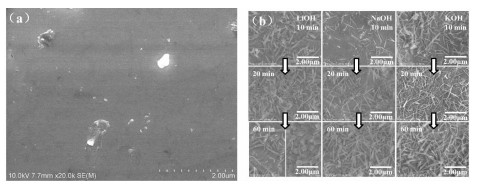
SEM images of the (REMg)2(NiAl)7 alloy powders before alkali solution treatment (a) and treated in different alkaline aqueous solutions (b)

E-Mg-Ni based AB3~3.8 type alloys with higher discharge capacities and fine electrochemical properties have been developed these years. They are potential alternatives of AB5-type alloys as the negative electrode of nickel-metal hydride (Ni-MH) battery[1-7]. However, the cyclic stability of such alloys is poor and it is easy to corrode in alkaline solutions. The performances of hydrogen storage alloy are related to the composition and the surface state. Alkaline treatment can improve the electrochemical properties of hydrogen storage alloy by changing the surface state, such as the high rate discharge capacity, cycle life, and electro-catalytic activity. In previous studies, alkaline aqueous solutions were mostly applied for treating AB5-type hydrogen storage alloys[8-15]. The improvement of the electrochemical performances of the alloy electrodes after the treatment in alkaline solutions is attributed to the Ni enrichment and the existence of the alkaline elements in the alloy sub-layers. They accelerates the H absorption on the alloy surface and helps the electron transportation between the alloy surfaces and the H2 or H2O molecule[8-11]. Besides, the consumption of electrolyte can be diminished after the alloy powder treated in alkaline solution when it is used as the negative electrode in nickel-metal hydride (Ni-MH) battery.
Recently, alkaline treatment has also been applied on RE-Mg-Ni based alloys. The hydrogen storage alloy of La0.6Nd0.2Mg0.2Ni3.3Co0.3 was treated in 6 mol·L-1 KOH alkaline solution[16]. The capacity retention rate of the alloy treated at 80 ℃ for 1 h increased by 9.35% and the high rate discharge-ability (HRD) increased by 26.7% when the discharge current density was 900 mA·g-1. The surface treatment of the La0.7Mg0.3Ni2.4Co0.6 hydrogen storage alloy with KOH solution containing KBH4 exhibited excellent electrochemical properties. The hydrogen storage capacity and the high rate discharge ability of the alloy electrode were improved, and the charge-transfer resistance of the alloy electrode was reduced[17]. Luo et al.[18] found with the increase of the process time of hot alkaline on La0.64Gd0.2Mg0.16Ni3.1Co0.3Al0.1 alloy, the magnetization intensity of alloy increased first and then decreased. The alloy electrode performance, which changed with the hot alkali processing time, was related to the formation of enriched Ni layers and their subsequent oxidation tendency as well as the precipitation of RE oxides on the alloy surface. Young et al.[19-20] compared the AB2, AB5 and A2B7 type hydrogen storage alloys treated with alkaline solutions and investigated the influence of the surface oxide structure on the electrochemical properties.
Alkaline treatment is a simple method to effectively improve the electrochemical properties. However, the kinds of alkali solutions, their concen-trations, and the treating temperature and time have great effects on the properties of alloys. In our previous study, the (REMg)2(NiAl)7 alloy was treated in LiOH aqueous solution[21].
The results show that LiOH solution could effectively remove the Mg elements on the alloy surface. The LiOH solution of relative high concen-tration reduced the formation of oxygen species on the surface of the alloy. We think the hydrogen storage alloy treated with different alkali solutions would have different corrosion surfaces and the oxide layers. Therefore, in this work, the alkaline treatment on the RE-Mg-Ni based hydrogen storage alloy with LiOH, NaOH and KOH solutions were investigated. The effects of different alkaline solutions on the surface compositions and structures of RE-Mg-Ni-based alloys were tested. The relationship between the electrochemical character and the surface state after the alkaline treatment was analyzed.
The commercial (REMg)2(NiAl)7 hydrogen storage alloy powders were obtained from Xiamen Tungsten Co., Ltd. RE elements in the alloy include La, Ce, Pr, Nd, etc. The phase composition of the alloy includes more than 90% (w/w) of A2B7-type crystal structure and a small amount of AB3, AB5, and A5B19 phases. The alkali treatment method for the alloy powder was immersing the alloy into the alkali solution of 363 K firstly, stirring for different times, and then pouring the upper alkaline solution out, stirring and washing with distilled water until pH=7, and vacuum drying at 333 K.
The 200 mg alloy powder was fully mixed with 800 mg nickel powder and cold pressed into a pellet of 16 mm diameter at 530 MPa pressure. The pellet was coated with nickel foam and then welded to the nickel band to make the negative electrode. The counter electrode is sintered Ni(OH)2/NiOOH. The electrolyte is 6 mol·L-1 KOH solution. Electrochemical measurements were carried out in a three electrode electrolytic cell at 298 K.
The working electrodes were charged at the current density of 60 mA·g-1 for 450 min, then discharged at the current density of 60 mA·g-1 to the cut-off voltage of -1.0 V. High rate discharge-ability (HRDi) was calculated by Ci/Cmax×100%, where Ci was the discharge capacity of the discharge current density of i mA·g-1 and Cmax was the maximum discharge capacity of the discharge current density of 60 mA·g-1. After the activation of 10 cycles, the charge and discharge current density of 300 mA·g-1 were used to test the cycle lives of the metal hydride electrodes.
Measurement of surface morphology and element content were observed using scanning electron microscopy (SEM) with EDS with a Hitachi-S4800 Unit operating at 10 kV. The pulse heating inert gas fusion-infrared absorption method (IR) was used to test the oxygen content of the alloy powder. The magnetic properties of the alloy surfaces were measured by vibrating sample magnetometer (VSM).
Fig. 1 shows the surface states of the untreated (REMg)2(NiAl)7 hydrogen storage alloy powders and the alloy powders treated with 6 mol·L-1 LiOH, NaOH and KOH aqueous solutions for various times. During the treatment, some elements, such as Mg, Al, and rare-earth metal elements, dissolved in the alkaline solution. The hydroxides and oxides of the dissolved elements increased gradually in the alkaline solutions, re-precipitate on the alloy surfaces, and serve as the barrier to further corrosion[22]. As can be seen in Fig. 1, with the treating time increases, the amount of the rod-like and needle-like products on the alloy surfaces raise on the alloy powders treated with 6 mol·L-1 NaOH and KOH solutions. On the alloy powder treated in 6 mol·L-1 LiOH solution the rod-like and needle-like products raised for the first 20 min. After 60 min treatment the rod-like and needle-like products diminished and the column-shaped things appeared in some regions.
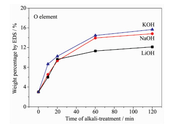
Because of the accumulation of the hydroxides or oxides, the O content increased. Fig. 2 shows the energy dispersive spectrometer (EDS) weight percen-tages of O elements of the (REMg)2(NiAl)7 hydrogen storage alloy powders treated with 6 mol·L-1 LiOH, NaOH and KOH aqueous solutions for various times. the O contents increased sharply in the first 20 min and then the rate of growth becomes slowing (Fig. 2). The order of the O contents on the alloy surfaces treated in different alkaline solutions (6 mol·L-1) is LiOH < NaOH < KOH. The sample treated with 6 mol·L-1 LiOH showed the lowest O content, indicating the inhibition of the oxygen containing species formation of 6 mol·L-1 LiOH solution on the alloy powder. The O contents were also tested using infrared adsorption methods and were listed in Table 1, which accords well with the EDS results.
 下载:
导出CSV
下载:
导出CSV
| Sample | Oxygen content by IR / % (w/w) | Magnetic material content / % (w/w) |
| Untreated | 0.14 | 0.40 |
| With LiOH treated 10 min | 0.28 | 0.54 |
| With LiOH treated 20 min | 0.63 | 1.22 |
| With LiOH treated 60 min | 0.70 | 1.81 |
| With NaOH treated 10 min | 0.34 | 0.62 |
| With NaOH treated 20 min | 0.44 | 0.80 |
| With NaOH treated 60 min | 0.98 | 2.04 |
| With KOH treated 10 min | 0.44 | 0.74 |
| With KOH treated 20 min | 0.62 | 1.01 |
| With KOH treated 60 min | 1.02 | 2.42 |
The porous alloy surfaces formed by the corrosion and etching of the alkaline solutions and the re-precipitation of the oxygen containing species were rich in Ni element in sub-layer. Because of its strong magnet the magnetic material content was calculated by dividing the sample magnetization by Ni powder magnetization. As shown in Table 1, the magnetic material contents of the alloy powders treated in different alkaline solutions (6 mol·L-1) increased with the treating time and were in the order of KOH>NaOH>LiOH. The Ni rich sub-layer is in favor of enhancing the activity for H absorption/desorption and the corrosion resistance of the alloy electrode. However, exorbitant Ni content could make the excessive corrosion of the alloy powder leading to the reduction of the maximum discharge capacity.
Fig. 3 shows the effect of the treating time on the discharge capacity and cycle life of the (REMg)2(NiAl)7 hydrogen storage alloy electrode treated with different alkaline aqueous solutions. The electrochemical prop-erties including the maximum discharge capacity at 1C, cycle life of 100 cycles, high rate discharge-ability, and charge retention rate at 25 ℃ for 180 h of the alloy electrodes treated in different alkaline aqueous solutions are listed in Table 2. The alkaline treatment corroded the alloy powder effectively. The discharge capacities of the alkaline treated alloy electrodes were all higher than that of the untreated electrode except for the alloy electrodes treated with 6 mol·L-1 NaOH and KOH aqueous solution for 60 min. The alloy electrode treated in 6 mol·L-1 NaOH aqueous solution for 10 min obtained the highest discharge capacity. With the treating time increases from 10 to 60 min, the maximum discharge capacity of the alloy electrode treated with 6 mol·L-1 LiOH, NaOH and KOH solutions decreased from 323.10 to 319.80 mAh ·g-1, from 330.36 to 309.03 mAh·g-1, and from 320.84 to 312.70 mAh·g-1, respectively. The order of the maximum discharge capacity reduction after the treatment from 10 to 60 min is NaOH>KOH>LiOH. The magnetic material contents and the oxygen contents both remarkably increased with the time for the alloy powders treated in NaOH and KOH solutions. The excessive corrosion of the alloy surface and too much oxygen containing species decreased the discharge capacity seriously[23]. After 100 cycles, the alloy electrodes treated with 6 mol·L-1 NaOH for 10 min and 6 mol·L-1 LiOH for 10 and 20 min showed higher discharge capacities (S100). The cyclic durability of the alloy electrodes treated in LiOH solution was better than the alloy electrodes treated in NaOH and KOH solutions.
 下载:
导出CSV
下载:
导出CSV
| Sample | Maximum discharge capacity / (mAh·g-1) | S100 / % | HRD900 / % | Charge retention rate / % |
| Untreated | 311.16 | 91.64 | 91.06 | 55.6 |
| With LiOH treated 10 min | 323.10 | 92.46 | 89.38 | 67.1 |
| With LiOH treated 20 min | 321.44 | 92.39 | 89.48 | 69.2 |
| With LiOH treated 60 min | 319.80 | 91.20 | 88.34 | 71.5 |
| With NaOH treated 10 min | 330.36 | 90.24 | 91.45 | 72.2 |
| With NaOH treated 20 min | 319.69 | 90.25 | 91.13 | 70.6 |
| With NaOH treated 60 min | 309.03 | 90.28 | 90.10 | 64.1 |
| With KOH treated 10 min | 320.84 | 89.30 | 90.87 | 71.0 |
| With KOH treated 20 min | 316.31 | 90.46 | 89.28 | 70.0 |
| With KOH treated 60 min | 312.70 | 90.61 | 88.06 | 66.0 |
As is shown in Table 2, the high rate discharge-abilities of the alloy electrodes treated for different times were in the order of NaOH>LiOH≈KOH. Only the HRD of the alloy electrode treated in 6 mol·L-1 NaOH solution for 10 min is higher than that of the untreated sample indicating the good activation of NaOH solution. The HRDs of the other alloy electrodes were all worse than the untreated sample. Although the Ni rich sub-layers are formed on the other samples, the fast-growing O containing species affected the HRD greatly. In addition, the alkaline treatment in our experiment did not add reducing agents[11-12]. The surface oxygen species could not be effectively removed.
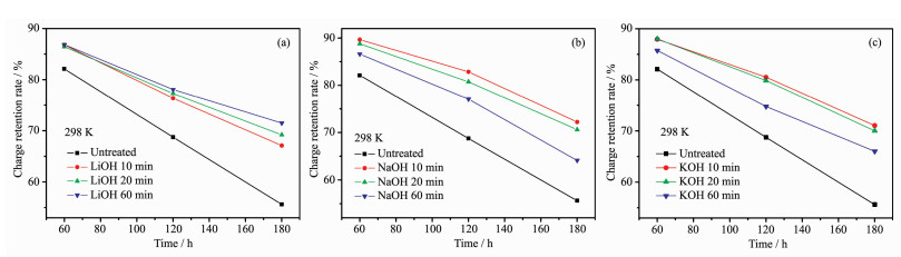
As is shown in Fig. 4, the charge retention rates of the treated alloy electrode were all better than that of the untreated sample. The improvement benefited from the oxidation layer and the Ni rich sub-layer on the alloy surface. With the increase of the treating time, the charge retention rate of the LiOH treated sample increased, but the charge retention rates of the NaOH and KOH treated samples decreased. This suggests that the alloy electrode treated in different alkaline solutions formed the surfaces of different compositions, which had different effects on the charge retention rate.
In conclusion, the sample treated with 6 mol·L-1 NaOH solution for 10 min shows the best electrochemical properties, including the maximum discharge capacity, the discharge capacity after 100 cycles, the HRD, and the charge retention rate.
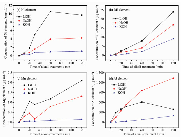
Fig. 5 shows the changes of Ni, rare-earth, Mg and Al contents by EDS analyses on the (REMg)2(NiAl)7 alloy surfaces treated with various alkaline aqueous solutions from 10 to 120 min. In order to reduce the randomness of the experimental results, several regions containing scores of alloy particles were selected, and then the average value of the test results was obtained. The surface content of oxygen varied greatly with the treating time, which had great influence on the content of other elements. Therefore, the contents of the Ni, rare-earth, Mg and Al element by EDS were calculated by removing the O content. Fig. 6 shows the ICP analyses of Ni, RE, Mg and Al elements dissolved in 6 mol·L-1 LiOH, NaOH and KOH solutions during the treatment. These results can help analyze the composition of the surface layer of the alkali treated alloy powder. In theory, with the increase of the treating time, the rare-earth, Mg and Al elements on the alloy surface dissolved firstly and then the dissolved element ions deposited as the hydroxides or oxides. As the accumulation and growing up on the alloy surface, the deposits would break off. Therefore, the EDS contents of these elements should decrease first, then rise, and in the end fall. Nickel element is not easily dissolved in alkali solution[24]. Because of the dissolution of other elements, the content of Ni on the alloy surface increased at the initial stage. With the deposition and breaking off of the oxygen containing species, the content of Ni first decreased and then increased (Fig. 5a). The EDS content of the Ni element on the most surface layer was different from the magnetic material content in Table 1, which represents the amount of the Ni atoms in the sub-layer of the alloy powders.
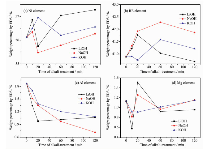
As can be seen in Fig. 5b, the RE contents of the 6 mol·L-1 LiOH and 6 mol·L-1 NaOH treated samples increased first and then decrease. There was no declining process at the initial stage suggesting the dissolution and deposition process was very fast. The RE contents of the alloy surfaces treated in NaOH and KOH reversed to decline at 60 min according to the falling off of the surface RE hydroxides. However, the RE content of the alloy surface treated in LiOH had a rapid decrease after 20 min treatment. The SEM images in Fig. 1 show that on the surface of sample treated with LiOH solution for 60 min the rod-shaped and needle like species diminished and in some regions the column-shaped things appeared. The RE hydroxides on the alloy surface were mostly rod like and needle like. This suggests that the composition of the surface oxygen containing species were changed. Compared with the samples treated with KOH and LiOH solutions, the amount of the RE hydroxides on the sample treated with NaOH solution was larger. And the Ni content of NaOH treated sample was the smallest.
The EDS and ICP results in Fig. 5c and Fig. 6c show that the dissolution and deposition of Mg element on the alloy surface treated with the alkali solutions before 20 min were both in the order of LiOH>NaOH>KOH. The Mg contents of the samples treated with LiOH and NaOH solutions at 20 min had sharp reverses at 20 min according to the falling off of the MgO or Mg(OH)2. This suggests the effective removal of the Mg element by LiOH and NaOH solutions. The EDS and ICP results in Fig. 5d and Fig. 6d show that the dissolution of Al element in the alkali solutions before 20 min were also in the order of LiOH>NaOH>KOH. The EDS results show that the Al contents on the alloy surface treated in NaOH and KOH solutions continued to decline after 20 min. The declining rate on the NaOH treated sample is much faster than that on the KOH treated sample. But the Al content on the alloy surface treated with LiOH solution raised slightly. We think the increase of the Al content was according to the deposition of the Al(OH)3.
Based on the above analyses, we find that the dissolution rates of alloy surface elements and the deposition rates of the dissolved elements were both in the order of LiOH>NaOH>KOH for the concentra-tion of 6 mol·L-1. The LiOH solution has the smallest polarity in the three alkaline solutions. Thus we think the solubility of the dissolved ions in LiOH solution is the lowest. In our experiment, the oxides or hydroxides of RE and Mg elements are easier to deposit and fall off with the accumulation and the oxides or hydroxides of Al element is easier to deposit on the LiOH treated alloy surface than on the KOH and NaOH treated alloy surfaces. Therefore, the surface layer of LiOH treated sample had the lower oxygen content and contains more Ni or its oxidized species, and Al oxygen species. We think the oxides and hydroxides layers formed in LiOH solution were more unfavorable for H adsorption and desorption. The surface oxide layer had good corrosion resistance, which slowed down the dissolution rate of elements on the alloy surface. Thus the decrease rate of the capacity was the smallest from 10 to 60 min treatment. The alloy electrode treated in LiOH solution had high cycle stability and increasing charge retention rate with the extension of the treating time.
The discharge capacity and the charge retention rate decreased the fastest with the increase of the treating time and the HRD property was the best for the alloy electrode treated with NaOH solution. The NaOH solution activated the surface of the alloy effectively, but also corroded the alloy powder fastest. According to the above analysis, the surface layer contained much more RE hydroxides. The loose surface layer will not prevent the further corrosion. Besides, the ICP result shows the concentration of Al ion increased fastest in NaOH solution with the increase of the treating time. The amount of dissolved Al ion was hundreds of times the amount of dissolved other ions. It has been proved Al element could relieve the alloy pulverization and the Al oxide layer on the alloy surface inhibited the alloy corrosion/oxidation in alkaline electrolyte[25-27]. The high dissolu-tion of Al in our experiment caused the decrease of Al element in the alloy powder and the serious oxidation of the alloy surface. Therefore, the discharge capacity and the charge retention rate of the alloy electrode decreased fastest (Fig. 2b). The treating time in NaOH solution should not be too long.
The dissolution and deposition rate of the alloy surface elements were both the lowest for the alloy powder treated with KOH. The activation of 6 mol·L-1 KOH solution for the alloy electrode was not remar-kable compared with 6 mol·L-1 LiOH and NaOH solu-tions. The discharge capacity decreased less than the sample treated with NaOH solution during 60 min treatment. Because of the slow deposition and falling off of the hydroxides or oxides, the oxygen content was the highest for the KOH treated sample. In our experiments, the electrochemical characteristics of the alloy electrode treated in 6 mol·L-1 KOH solution were not very well. The optimum treatment time and concentration of KOH solution should be further improved.
The (REMg)2(NiAl)7 hydrogen storage alloy powders were treated with 6 mol·L-1 LiOH, NaOH and KOH aqueous solutions for different times. The alloy powder treated with 6 mol·L-1 NaOH solution for 10 min shows the best electrochemical properties, includ-ing the maximum discharge capacity, the discharge capacity after 100 cycles, the HRD and the charge retention rate. Different compositions and structures of the alloy surfaces lead to different electrochemical properties of the alloy electrodes. It is found that LiOH could effectively diminish the oxygen content of the alloy surface. The surface layer of LiOH treated sample contained more Ni, Al and their oxidized species, and had good corrosion resistance. Therefore, the alloy electrode treated in LiOH solution had high cycle stability, low HRD property, and increasing charge retention rate with the extension of the treating time. The discharge capacity of the alloy electrode treated in 6 mol·L-1 NaOH solution decreased remar-kably with the increase of the treating time. The surface layer of NaOH treated sample contained much more RE hydroxides. At the same time, the Al element was quickly dissolved. The loose surface layer could not prevent further corrosion. The dissolu-tion rate of the alloy surface elements and the deposi-tion rate of the dissolved elements were both lower in 6 mol·L-1 KOH solution than in the same concentra-tion of NaOH and LiOH.
Iwase K, Terashita N, Mori K, et al. Int. J. Hydrogen Energy, 2016, 41:1074-1079 doi: 10.1016/j.ijhydene.2015.11.052
Wu C, Zhang L, Liu J J, et al. J. Alloys Compd., 2017, 693:573-581 doi: 10.1016/j.jallcom.2016.09.206
张新波, 赵敏寿.高等化学学报, 2003, 24:1680-1682 http://xueshu.baidu.com/s?wd=paperuri%3A%28947a8c0704be8190f8da04167652be65%29&filter=sc_long_sign&tn=SE_xueshusource_2kduw22v&sc_vurl=http%3A%2F%2Fwww.cnki.com.cn%2FArticle%2FCJFDTotal-GDXH200309036.htm&ie=utf-8&sc_us=6412147755115383215ZHANG Xin-Bo, ZHAO Min-Shou. Chem. J. Chinese. University, 2003, 24:1680-1682 http://xueshu.baidu.com/s?wd=paperuri%3A%28947a8c0704be8190f8da04167652be65%29&filter=sc_long_sign&tn=SE_xueshusource_2kduw22v&sc_vurl=http%3A%2F%2Fwww.cnki.com.cn%2FArticle%2FCJFDTotal-GDXH200309036.htm&ie=utf-8&sc_us=6412147755115383215
Liu Z P, Yang S Q, Li Y, et al. J. Rare Earths, 2015, 33:397-402 doi: 10.1016/S1002-0721(14)60432-4
Zhang Y H, Zhang W, Yuan Z. Int. J. Hydrogen Energy, 2017, 42:14227-14245 doi: 10.1016/j.ijhydene.2017.04.198
Zhang X B, Sun D Z, Yin W Y, et al. ChemPhysChem, 2005, 6:520-525 doi: 10.1002/(ISSN)1439-7641
Zhang X B, Sun D Z, Yin W Y, et al. Electrochim. Acta, 2005, 50:1957-1964 doi: 10.1016/j.electacta.2004.09.016
Zhou W H, Tang Z Y, Zhu D, et al. J. Alloys Compd., 2017, 692:364-374 doi: 10.1016/j.jallcom.2016.08.292
Karwowska M, Jaron T, Fijalkowski K J, et al. J. Power Sources, 2014, 263:304-309 doi: 10.1016/j.jpowsour.2014.04.050
Zhang P L, Wang X L, TU J P, et al. J. Rare Earths, 2009, 27:510-513 doi: 10.1016/S1002-0721(08)60279-3
Chen W X, Tang Z Y, Guo H T, et al. J. Power Sources, 1998, 74:34-39 doi: 10.1016/S0378-7753(98)00007-X
Chen W X. J. Power Sources, 2001, 92:102-107 doi: 10.1016/S0378-7753(00)00509-7
Kim H K, Yang D C, Jang I S, et al. Int. J. Hydrogen Energy, 2009, 34:9570-9575 doi: 10.1016/j.ijhydene.2009.09.097
Santos D M F, Sequeira C A C, Lobo R F M. Int. J. Hydrogen Energy, 2010, 35:9901-9909 doi: 10.1016/j.ijhydene.2009.11.015
Zhou Y, Dag N. J. Alloys Compd., 2016, 664:59-64 doi: 10.1016/j.jallcom.2015.12.170
Zhou N, Ma Y D, Ding Y, et al. Battery, 2013, 43:88-90
Xiao L L, Wang Y J, Liu Y, et al. Int. J. Hydrogen Energy, 2008, 33:3925-3929 doi: 10.1016/j.ijhydene.2008.01.045
曾书平, 罗永春, 李新宇, 等.中国稀土学报, 2014, 32:701-709 http://www.cnki.com.cn/Article/CJFDTotal-XTXB201406009.htmZENG Shu-Ping, LUO Yong-Chun, LI Xin-Yu, et al. Journal of the Chinese Society of Rare Earths, 2014, 32:701-709 http://www.cnki.com.cn/Article/CJFDTotal-XTXB201406009.htm
Young K, Huang B, Regmi R K, et al. J. Alloys Compd., 2010, 506:831-840 doi: 10.1016/j.jallcom.2010.07.086
Young K, Chao B, Liu Y, et al. J. Alloys Compd., 2014, 606:97-104 doi: 10.1016/j.jallcom.2014.04.033
Yuan H P, Yang K, Jiang L J, et al. Int. J. Hydrogen Energy, 2015, 40:4623-4629 doi: 10.1016/j.ijhydene.2015.01.167
Su G, He Y H, Liu K Y. Int. J. Hydrogen Energy, 2012, 37:12384-12392 doi: 10.1016/j.ijhydene.2012.05.149
Lin C H, Lin K M, Chou H T, et al. J. Alloys Compd., 2003, 358:281-287 doi: 10.1016/S0925-8388(03)00030-6
Ikoma M, Komori K, Kaida S, et al. J. Alloys Compd., 1999, 284:92-98 doi: 10.1016/S0925-8388(98)00740-3
Liu J J, Han S M, Li Y, et al. J. Alloys Compd., 2015, 619:778-787 doi: 10.1016/j.jallcom.2014.09.041
Balogun M S, Wang Z M, Chen H X, et al. Int J. Hydrogen Energy, 2013, 38:10926-10931 doi: 10.1016/j.ijhydene.2013.02.139
Liu Y F, Pan H G, Gao M X, et al. Int J. Hydrogen Energy, 2008, 33:124-133 doi: 10.1016/j.ijhydene.2007.09.016

Figure 1 SEM images of the (REMg)2(NiAl)7 alloy powders before alkali solution treatment (a) and treated in different alkaline aqueous solutions (b)

Figure 2 EDS weight percentages of O element on the surfaces of the (REMg)2(NiAl)7 hydrogen storage alloy powders treated in different alkaline aqueous solutions

Figure 3 Effect of the treating time on the discharge capacity and cycle life of the (REMg)2(NiAl)7 hydrogen storage alloy electrode treated with different alkaline aqueous solutions

Figure 4 Effect of the treating time on the charge retention rate of the (REMg)2(NiAl)7 hydrogen storage alloy electrode treated with LiOH (a), NaOH (b) and KOH (c) aqueous solutions

Figure 5 EDS of (a) Ni, (b) rare-earth, (c) Al and (d) Mg element on the surfaces of the (REMg)2(NiAl)7 hydrogen storage alloy powders treated in different alkaline aqueous solutions

Figure 6 ICP analysis of (a) Ni, (b) RE, (c) Mg and (d) Al element dissolved from the alloy surface in alkaline solutions during treatment
Table 1. Oxygen and magnetic material contents of the alloy powders treated in different alkaline aqueous solutions
| Sample | Oxygen content by IR / % (w/w) | Magnetic material content / % (w/w) |
| Untreated | 0.14 | 0.40 |
| With LiOH treated 10 min | 0.28 | 0.54 |
| With LiOH treated 20 min | 0.63 | 1.22 |
| With LiOH treated 60 min | 0.70 | 1.81 |
| With NaOH treated 10 min | 0.34 | 0.62 |
| With NaOH treated 20 min | 0.44 | 0.80 |
| With NaOH treated 60 min | 0.98 | 2.04 |
| With KOH treated 10 min | 0.44 | 0.74 |
| With KOH treated 20 min | 0.62 | 1.01 |
| With KOH treated 60 min | 1.02 | 2.42 |
 下载: 导出CSV
Table 2. Electrochemical properties of the alloy electrodes treated in different alkaline aqueous solutions
| Sample | Maximum discharge capacity / (mAh·g-1) | S100 / % | HRD900 / % | Charge retention rate / % |
| Untreated | 311.16 | 91.64 | 91.06 | 55.6 |
| With LiOH treated 10 min | 323.10 | 92.46 | 89.38 | 67.1 |
| With LiOH treated 20 min | 321.44 | 92.39 | 89.48 | 69.2 |
| With LiOH treated 60 min | 319.80 | 91.20 | 88.34 | 71.5 |
| With NaOH treated 10 min | 330.36 | 90.24 | 91.45 | 72.2 |
| With NaOH treated 20 min | 319.69 | 90.25 | 91.13 | 70.6 |
| With NaOH treated 60 min | 309.03 | 90.28 | 90.10 | 64.1 |
| With KOH treated 10 min | 320.84 | 89.30 | 90.87 | 71.0 |
| With KOH treated 20 min | 316.31 | 90.46 | 89.28 | 70.0 |
| With KOH treated 60 min | 312.70 | 90.61 | 88.06 | 66.0 |
下载: 导出CSV

 扫一扫看文章

扫一扫关注我们
 下载:
下载: