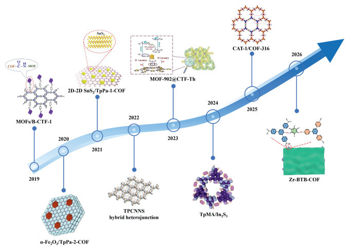
Figure 1.
Timeline for the development of representative COF-based heterojunction photocatalysts.

Interfacial engineering in COF-based S-scheme heterojunctions for enhanced photocatalysis
Yingyin Mo , Xinghua Wen , Ziyang Ke , Can Huang , Rongchen Shen , Song Wang , Xiang Li , Jianmin Luo , Xin Li


With the increasing prominence of global energy crises and environmental challenges, research into sustainable development and the exploitation of green and clean energy has become a focal point [1]. Solar light, as an inexhaustible and clean energy source, coupled with photocatalysis as a green and sustainable technology driven by solar energy, demonstrates immense potential in environmental remediation and energy conversion fields [2-4]. This encompasses key applications such as photocatalytic water splitting for hydrogen production, water oxidation for hydrogen peroxide generation, photocatalytic CO2 reduction, pollutant degradation, and photocatalytic organic transformations [5-12]. Photocatalysis not only powers various chemical reactions but also lays the foundation for green energy conversion, environmental protection, and sustainable development, thereby becoming a core support and frontier direction driving the synergistic advancement of green energy and environmental governance.
In 1972, the discovery of photocatalytic water splitting on titanium dioxide by Fujishima et al., which was subsequently applied to the degradation of organic pollutants, significantly propelled the development of inorganic photocatalysts [13,14]. Representative systems of inorganic photocatalysts include titanium dioxide, zinc oxide, tungsten oxide, iron(Ⅲ) oxide, vanadium dioxide, and various metal oxides, sulfides, carbides, nitrides, as well as composites containing noble or transition metals [15-23]. These materials typically possess advantages such as high chemical and thermal stability, ease of large-scale synthesis, and optoelectronic properties that can be optimized through compositional and morphological tuning [24]. Consequently, they are extensively utilized in pollutant degradation, water and air purification, and solar-driven chemical transformations (e.g., hydrogen evolution and CO2 reduction) [25,26]. In recent years, the research focus has shifted from single semiconductors to advanced strategies such as doping, surface modification, heterojunction/composite construction, noble metal or cocatalyst loading, nanostructuring, porous/hollow structure design, and coupling with two-dimensional materials [27-30]. These approaches primarily aim to broaden the visible-light response range and suppress electron-hole recombination. However, despite these advancements, the practical applications of inorganic photocatalysts remain limited by inherent drawbacks [31-33], including wide bandgaps, high electron-hole recombination rates, insufficient visible-light activity, and suboptimal catalytic selectivity or overall activity. Simultaneously, the past two decades have witnessed the rapid development of organic photocatalysts, particularly COFs and covalent triazine frameworks (CTFs) [34,35]. Owing to their designable molecular units, extended π-conjugated networks, and controllable pore architectures, they have demonstrated remarkable potential in visible-light absorption, charge carrier transport, and selective catalysis. Since the pioneering report of COF-1 and COF-5 by Yaghi and co-workers in 2005 [36], ordered porous structures have been successfully constructed via reversible condensation reactions. COFs represent a class of crystalline porous materials formed by covalently linking organic building blocks, such as aromatic compounds and nitrogen-containing heterocycles. They are characterized by highly ordered porous frameworks, large specific surface areas, robust chemical stability, and tunable electronic structures. Their pore sizes typically span from the microporous (<2 nm) to the macroporosity (>50 nm) regimes [37]. Such porous architectures not only provide abundant active sites and enlarge the contact area with reactants, but also facilitate mass transfer, thereby enabling the highly efficient diffusion of both reactants and products. Furthermore, the long-range ordered crystalline nature of COFs endows them with regularly aligned conjugated structures. This structural feature is highly conducive to the delocalization and transport of electrons, thereby enhancing charge carrier mobility. Consequently, this facilitates the efficient separation and transfer of photogenerated charges, accelerates the kinetics of photocatalytic reactions, and simultaneously bolsters their thermal and chemical stability. Through the judicious selection of constituent monomers or via post-synthetic modifications, the energy band positions and surface chemistry of COFs can be precisely engineered, which enables the realization of tunable donor-acceptor configurations and the precise, molecular-level positioning of catalytic sites. In 2008 [38], Kuhn et al. reported the synthesis of highly stable, thermostable, and porous CTFs via the ionothermal cyclotrimerization of nitrile building blocks. Subsequently, Stegbauer et al. [39] in 2014 reported a COF based on 1,3,5-tris(4-formylphenyl)triazine (TFPT-COF), demonstrating for the first time continuous hydrogen evolution under visible-light irradiation. These pioneering works highlighted the potential advantages of azine/triazine-based organic frameworks in visible-light absorption and the separation of photogenerated electron-hole pairs. Constructed with triazine units as the backbone, CTFs generally exhibit superior thermal and chemical stability, stronger electron-accepting properties, and enhanced photochemical reduction capabilities [40,41]. However, they typically suffer from relatively poor crystallinity, and their structural uniformity and pore ordering rarely reach the levels observed in COFs. Consequently, benefiting from their highly designable crystalline porous frameworks and ordered π-π stacking, COFs provide an exceptional platform among organic photocatalysts for the precise introduction and positioning of catalytic sites. By judiciously selecting building blocks, tuning linker lengths and topologies, or employing post-synthetic modifications, one can systematically modulate their light absorption range, energy band alignment, carrier mobility, and interfacial charge transfer, thereby optimizing photocatalytic activity and selectivity. In contrast, CTFs frequently excel in photoreduction reactions, owing to their strongly conjugated backbones, exceptional chemical and thermal robustness, and intrinsic electron-accepting nature. Furthermore, their electronic structures and band positions can be further tailored via monomer design, heteroatom doping, or conjugation modulation to significantly boost reduction efficiency and long-term operational stability.
The diverse structural characteristics and robust covalent linkages of COFs endow them with excellent photochemical stability [42-44], enabling the preservation of structural integrity during photocatalytic processes while maintaining the tunability of their molecular architecture and stacking modes. These distinct structural attributes confer a range of unique physicochemical properties upon COFs, unlocking broad potential in photocatalytic applications, including solar-driven hydrogen evolution, H2O2 production, organic transformations, and environmental photodegradation. Nevertheless, the deployment of COFs as photocatalysts still faces several critical challenges:
(ⅰ) Synthesis and crystallinity often present a paradox; bulky or highly conjugated linkers can compromise framework integrity, leading to reduced crystallinity that adversely affects charge migration and catalytic performance.
(ⅱ) Certain reversible linkages are susceptible to attack by substrates or solvents under catalytic conditions, which limits their overall stability and application scope.
(ⅲ) Bandgap engineering necessitates a delicate balance between maximizing light harvesting and maintaining appropriate redox potentials, as either excessively wide or narrow bandgaps are detrimental to catalytic efficiency.
(ⅳ) Scalable synthesis, precise morphological regulation, and conductivity improvement continue to necessitate breakthroughs in processing methodologies and structural engineering.
(ⅴ) Compared to inorganic or hybrid systems, the long-term durability of certain organic frameworks under prolonged irradiation or strong oxidative conditions remains to be rigorously verified.
Furthermore, the rapid separation and transport of photogenerated electron-hole pairs are pivotal for enhancing photocatalytic efficiency. Although the ordered porous frameworks and extensively conjugated backbones of COFs provide advantageous pathways for charge separation and mitigate recombination probabilities, their pristine forms often suffer from severe limitations when used as standalone photocatalysts. Factors such as rapid charge carrier recombination, sluggish migration kinetics, and an insufficiency in both the abundance and intrinsic activity of catalytic sites severely restrict the overall photocatalytic performance of organic frameworks, including COFs and CTFs.
Although research on COF-based S-scheme heterojunctions has made significant strides (Fig. 1), existing reviews primarily focus on the enumeration of performance metrics or the summarization of synthetic strategies, leaving a notable gap in the in-depth investigation of the fundamental driving mechanisms governed by interfacial interactions. From a physicochemical perspective, interfacial forces of varying magnitudes ranging from van der Waals forces and π-π stacking to robust chemical bonds, directly dictate the degree of band bending, the intensity of the built-in electric field (IEF), and the kinetics of charge transfer by modulating electron cloud overlap and charge density distribution at the interface; yet, these critical scientific nuances remain systematically underexplored. To address this deficiency, this review centers on the theme of interfacial engineering, first establishing a unified theoretical framework for understanding COF-based S-scheme heterojunctions. We specifically analyze the functional roles of COFs as oxidation or reduction components and examine how interfacial electronic coupling enables precise control over charge carrier dynamics. Building upon this, we systematically categorize the synthetic strategies for constructing multi-level interfacial interactions, critically evaluate advanced characterization techniques for probing interfacial engineering and carrier dynamics, and provide a comprehensive overview of their applications in photocatalytic H2 evolution, H2O2 photosynthesis, CO2 reduction, and the degradation of organic pollutants. Finally, this review discusses current challenges and future opportunities, aiming to provide a solid theoretical foundation and experimental guidelines for the rational design of efficient and stable COF-based S-scheme photocatalytic systems via precise interfacial chemistry.
COF-based photocatalytic systems have attracted considerable attention in solar-driven chemical conversion owing to their highly ordered pore architectures, programmable electronic structures, and favorable light-harvesting capabilities [45-47]. The photocatalytic process is intrinsically a multistep coupled pathway involving light absorption, exciton generation, charge separation, interfacial migration, and surface redox reactions (Figs. 2a and b) [48-51]. As schematically illustrated in the kinetic diagram of photocatalysis, incident photons are first absorbed by the COF framework to generate excited states or excitons, which then undergo spatial separation into electrons and holes. These charge carriers are subsequently transported through the conjugated framework or across heterointerfaces, while their migration competes with bulk and surface recombination. Once reaching the catalyst surface, the separated charges participate in interfacial adsorption and redox transformations of reactant molecules. In this context, the photocatalytic rate is governed not only by thermodynamic energy-level alignment, but also by the kinetics of charge generation, diffusion, transfer, and surface utilization [52,53]. Therefore, the synergistic optimization of thermodynamic driving force and kinetic charge transport is crucial for determining the overall catalytic performance.
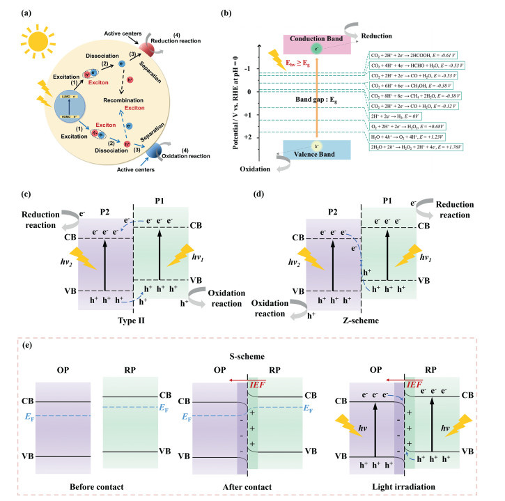
From a thermodynamic perspective, the photocatalytic activity of COFs primarily arises from the precise regulation of their electronic band structure enabled by molecular-level structural design. By introducing donor–acceptor building units [54,55], tuning the electron density of the conjugated framework [56], or incorporating specific functional groups [57,58], researchers can effectively manipulate the frontier orbital energies (HOMO/LUMO) of COFs, thereby aligning their conduction/valence band positions with the redox potentials required for target reactions. In heterojunction systems, upon contact between COFs and other semiconductors, interfacial charge redistribution occurs during Fermi level (EF) equilibration, leading to the formation of an IEF and the associated band bending. This interfacial field provides a thermodynamic driving force for the directional migration of photogenerated electrons and holes, thereby facilitating charge separation and ensuring that the carriers involved in surface reactions retain sufficient reducing and oxidizing power, respectively.
From a kinetic standpoint, the unique structural characteristics of COFs greatly promote charge transport, separation, and utilization efficiency. First, the ordered π-π stacking and highly conjugated backbone of COFs establish low-barrier pathways for charge transport, shortening the migration distance of photogenerated carriers from their generation sites to active centers and thus suppressing bulk recombination [59]. Second, the porous framework and high surface area of COFs favor the adsorption and enrichment of reactant molecules, increasing the local concentration around active sites and reducing diffusion resistance through confinement effects, thereby improving the apparent reaction kinetics [60]. Moreover, in heterojunctions governed by an S-scheme mechanism, interfacial selective charge transfer preferentially eliminates low-energy carriers while preserving high-energy electrons and holes with strong redox capabilities [61,62]. This spatial separation of charge carriers not only enhances charge separation efficiency but also maintains strong redox potentials, ultimately leading to improved reaction rates and product selectivity.
Overall, the photocatalytic performance of COFs is governed by the interplay of electronic structure, light harvesting, carrier transport, and surface active sites. An optimal bandgap and suitable band-edge alignment enable efficient solar absorption and provide the thermodynamic driving force for target redox reactions. Meanwhile, strong light absorption, long carrier diffusion length, and high mobility suppress recombination and promote charge delivery to the surface. In addition, abundant and accessible active sites facilitate reactant adsorption, intermediate stabilization, and reaction kinetics. For COFs, extended π-conjugation, high surface area, and tailored porosity further improve charge transport and site utilization, thereby enhancing photocatalytic activity and selectivity.
In photocatalytic systems, heterojunction engineering has been extensively exploited to enhance the separation efficiency of photogenerated charge carriers, thereby boosting catalytic performance [63-65]. Traditionally, Type-Ⅱ heterojunctions have been utilized to facilitate the spatial separation of electrons and holes through staggered band alignment, which effectively suppresses charge recombination (Fig. 2c) [66-68]. Guo et al. constructed a COF/COF Type-Ⅱ heterojunction, TpPa/TpDz, which enabled efficient and directional photogenerated charge transfer and exhibited excellent photocatalytic performance in both H2O2 synthesis and benzylamine oxidation coupling. Mechanistic studies showed that the heterojunction interface promotes effective separation of electrons and holes, thereby significantly improving charge carrier utilization efficiency [67]. Besides, Gao et al. constructed a Se-g-C3N4/ZnO (Se-CN/ZnO) and MnCo2O4 (MCO) Type-Ⅱ heterojunction, which synergistically activated peroxymonosulfate (PMS) to generate SO4·-/·OH, enabling efficient degradation of levofloxacin hydrochloride (LEV) and various pharmaceutical and personal care products (PPCPs) [68]. However, this architecture inherently suffers from thermodynamic trade-offs: The migration of electrons from a higher-energy conduction band to a lower one, and holes from a lower-energy valence band to a higher one, inevitably results in significant energy loss. Consequently, the redox potentials of the remaining charge carriers are compromised, which limits the overall photocatalytic activity. To circumvent these limitations, Z-scheme heterojunctions were developed, incorporating redox mediators (e.g., Fe3+/Fe2+) to shuttle electrons from the conduction band of one semiconductor (P2) to the valence band of another (P1) (Fig. 2d) [69,70]. This design theoretically enables the spatial separation of carriers while preserving the potent redox capabilities of the electrons in the P2 conduction band and the holes in the P1 valence band [71,72]. Wang and co-workers constructed a double direct Z-scheme BiOBr@CDs-TiO2-x heterojunction, in which the Z-scheme charge transfer pathway enabled efficient electron–hole separation while preserving strong redox capability, thereby markedly enhancing visible-light antibacterial performance [73]. Subsequently, Yang et al. constructed a sulfonyl-linked S-C4N/Fe2O3 Z-scheme heterojunction, which enhanced charge separation and preserved redox capability, enabling efficient solar energy storage in neutral seawater [74]. In practice, however, the charge transfer pathways in Z-scheme systems are often more complex than the idealized model; photogenerated electrons frequently exhibit a preference for transfer pathways that deviate from theoretical predictions. Furthermore, the reliance on liquid-phase redox mediators imposes significant constraints, including sensitivity to solution pH, potential interference with light absorption by the semiconductors, and a restricted scope of application. In contrast, S-scheme heterojunctions have recently garnered substantial attention [75-78]. Their distinct charge-transfer mechanism allows for the simultaneous achievement of efficient carrier separation and the retention of strong redox potentials, offering a superior alternative to traditional heterojunction architectures [79]. Typically, an S-scheme heterojunction comprises two semiconductors with disparate band structure, wherein one semiconductor serves as the oxidation half-reaction site and the other acts as the reduction half-reaction site [80-84]. Interfacial charge transfer is facilitated by appropriate solid-state electron mediators, such as metal nanoparticles or conductive polymers. This unique architectural design dictates that photogenerated electrons and holes are selectively preserved in the respective semiconductors exhibiting the most potent reduction and oxidation potentials, thereby driving highly efficient photocatalytic processes [85,86]. Concurrently, the rational pairing of semiconductors with complementary bandgaps within the S-scheme configuration enables the precise modulation and broadening of the optical absorption spectrum.
Typically, photocatalysts characterized by a high work function (Φ) exhibit a relatively low EF and robust oxidative capacity, thereby designated as oxidation photocatalysts (OP). Conversely, those with a low work function possess a higher EF and potent reductive ability, termed reduction photocatalysts (RP) (Fig. 2e) [87,88].
An S-scheme heterojunction is formed by coupling an OP and a RP, whose Fermi levels differ prior to contact. Upon interface formation, electrons migrate from the RP to the OP until Fermi-level equilibration is reached, generating band bending and an interfacial IEF directed from the RP to the OP. Under illumination, this internal field, together with interfacial band bending, drives the selective recombination of low-energy electrons in the OP with low-energy holes in the RP, while preserving high-energy electrons in the RP conduction band and holes in the OP valence band. As a result, the RP and OP retain strong reduction and oxidation abilities, respectively. However, photogenerated carriers that do not participate in this directional transfer may undergo radiative recombination or be trapped by defects and surface states, leading to reduced carrier mobility, loss of usable electrons, and weakened redox capacity. These parasitic loss pathways remain a key limitation for further improving the performance of S-scheme heterojunction photocatalysts.
In previous research, it is generally recognized that constructing COF-based S-scheme heterojunctions can resolve the three major bottlenecks of inadequate light absorption, carrier recombination, and restricted interfacial transport by synergistically designing the photoresponse, charge separation, and interfacial band alignment [89-92]. Furthermore, the tunable π-conjugated frameworks and designable topologies of COFs allow for the introduction of functional groups to extend visible/NIR light absorption. Their porous structures and high specific surface areas can expose a massive number of catalytic sites and shorten the diffusion paths of carriers to the interface [93,94]. Therefore, the structural design and regulation of COF-based S-scheme heterojunctions mainly proceed from the following three fundamental aspects:
(ⅰ) Optimization of light absorption and charge separation efficiency. Constructing porous frameworks and well-engineered heterointerfaces is an effective strategy to enhance photogenerated carrier separation and product selectivity. Owing to the different bandgaps and absorption edges of COF components, coupling COFs with narrow- or wide-bandgap semiconductors enables spectral complementarity: The former extend absorption into the long-wavelength region, whereas the latter harvest higher-energy photons, thereby broadening the overall light-response range and improving photocatalytic performance [95,96]. Meanwhile, interfacial band bending and the built-in electric field facilitate the spatial separation of electrons and holes, suppress recombination, and improve quantum efficiency and selectivity.
(ⅱ) Interfacial band alignment and directional charge migration. The S-scheme mechanism relies on an appropriate energy-level offset between two components, which generates a built-in electric field or interfacial potential barrier. This promotes the preferential recombination of low-energy electrons and holes at the interface, while preserving strongly reductive electrons and strongly oxidative holes in the respective redox-active components. In COF-based systems, precise tuning of the highest occupied molecular orbital (HOMO) or lowest unoccupied molecular orbital (LUMO) levels through molecular and interfacial engineering is therefore essential. In addition, introducing interfacial dipoles or surface functional groups can further improve S-scheme charge transfer, optimize band alignment, and accelerate surface redox kinetics.
(ⅲ) Defect engineering and topological design for carrier transport. Controlled defects, heteroatom doping, and tailored topological architectures can synergistically optimize interfacial coupling and charge transport. At the atomic scale, defects and dopants modulate the local electronic structure and Fermi level, and may create shallow traps that function as charge-transfer relay sites. Single-atom or metal-site anchoring can further strengthen metal-support interactions and promote internal electric-field formation. Meanwhile, proper defect regulation can passivate deep traps and suppress non-radiative recombination. At the structural level, topological engineering shortens carrier diffusion distance, enlarges the effective interfacial area, and establishes directional transport pathways, thereby reducing transport resistance and enhancing charge utilization.
Collectively, these strategies promote rapid and directional carrier migration to surface active sites, extending carrier lifetime and improving photocatalytic activity and selectivity.
S-scheme heterojunctions are photocatalytic systems formed by coupling two semiconductors with complementary band structures. Their defining feature is the directional migration of photogenerated carriers, driven by interfacial charge redistribution, band-edge offsets, and the built-in electric field, which promotes efficient spatial separation of electrons and holes under illumination [97-99]. In this process, low-energy electrons and holes preferentially recombine at the interface, whereas high-energy electrons and holes are retained in the reduction and oxidation components, respectively, thereby preserving strong redox potentials and enhancing photocatalytic reaction kinetics. Typically, the oxidation component possesses a more positive valence band (VB) and retains highly oxidative holes, while the reduction component has a more negative conduction band (CB) and preserves strongly reductive electrons. In COF-based S-scheme heterojunctions, COF units can serve as either the photo-oxidation or photo-reduction center.
As shown in Scheme 1, the role of COFs in S-scheme heterojunctions is strongly influenced by their intrinsic structural and electronic features. In general, COFs functioning as oxidation terminals tend to possess electron-deficient backbones, deeper VB positions, strong hole-stabilizing capability, and high oxidative driving force, which collectively favor the retention of energetic holes and the promotion of oxidation half-reactions. In contrast, COFs serving as reduction terminals usually feature electron-rich conjugated frameworks, higher CB/LUMO levels, efficient charge-transport pathways, and abundant reduction-active sites, enabling effective electron accumulation and facilitating reduction reactions. Overall, rational structural engineering of COFs, such as donor–acceptor design, heteroatom incorporation, and conjugation extension, which offers a powerful strategy to tune their band structures and interfacial charge behaviors, thereby enabling precise terminal matching and improving the performance of S-scheme heterojunction photocatalysts. Given that COF materials introduced as distinct functional termini exhibit significant disparities in band structure engineering strategies, interfacial charge dynamics, and functional site allocation mechanisms, the following sections will systematically elucidate the selection criteria and representative examples for COF materials serving as oxidation and reduction ends, respectively.
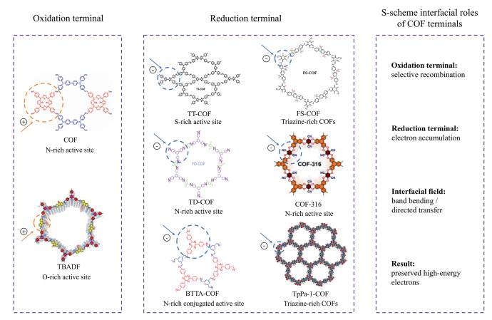
Within the S-scheme heterojunction, the COF component serves as the oxidation terminal, facilitating the spatial accumulation of photogenerated holes in its VB. By leveraging its tunable electronic structure and surface chemical properties, the COF enables strong interactions with reactants (e.g., H2O or O2), thereby lowering the activation energy for intermediate formation. This molecular-level design not only ensures an optimal oxidation potential but also significantly enhances the catalytic turnover and product selectivity. Consequently, some researchers have employed COFs as the oxidation terminal to construct S-scheme heterojunctions.
In this regard, Cui et al. fabricated a core-shell S-scheme heterostructure (COF-ZIS) through the interfacial integration of ZnIn2S4 (ZIS) and a π-conjugated porphyrin-based COF [100]. This heterostructure benefits from the moderate bandgap of ZIS (2.0–2.8 eV) and its strong visible-light response, while the porphyrin moieties embedded in the COF backbone furnish an extended π-conjugated network, enhanced photon-harvesting capability, and electronically adjustable redox-active sites, all of which are critical structural features for facilitating charge separation and promoting oxidative photocatalytic processes (Fig. 3a). Upon contact, the lower Fermi level of the COF relative to ZIS drives spontaneous electron transfer from ZIS to the COF until interfacial equilibrium is established (Fig. 3b). This charge redistribution leads to band bending in both components and generates an IEF directed from ZIS to the COF. Under illumination, the IEF promotes the selective recombination of low-energy electrons in the COF LUMO with low-energy holes in the ZIS valence band, thereby preserving the high-energy holes on the COF HOMO and the high-energy electrons in the ZIS conduction band. This spatial and energetic separation is characteristic of an S-scheme pathway and is strongly dependent on the electronic structure of the COF itself. In this heterostructure, the porphyrin-based COF functions as the oxidation terminal, where its HOMO-localized holes are consumed by sacrificial S2–/SO32– species, while ZIS serves as the reduction terminal, where electrons accumulated in the conduction band drive proton reduction to H2. Therefore, the photocatalytic enhancement originates not only from the heterojunction architecture, but also from the molecularly engineered COF backbone, whose porphyrin-based π-conjugated structure governs light absorption, energy-level alignment, and oxidation-site functionality.
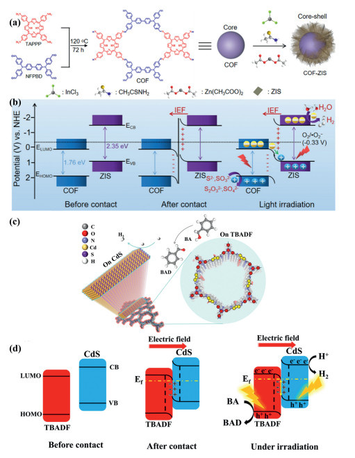
Similarly, Feng et al. synthesized a fluorenone-based covalent organic framework (TBADF) via the solvothermal copolymerization of 2,7-dinitro-9-fluorenone (DF) and 2,4,6-tris(4-benzaldehyde)-1,3,5-triazine (TBA) [101], illustrating how electron-deficient building blocks can tailor the electronic structure of a COF for photocatalysis. The incorporation of fluorenone and triazine motifs endows TBADF with a conjugated yet electron-poor backbone, which is favorable for lowering the Fermi level, tuning the frontier orbital distribution, and stabilizing photogenerated holes. By integrating CdS nanoparticles with 5 wt% TBADF through an electrostatic self-assembly strategy, a CdS-TBADF S-scheme heterojunction was formed (Fig. 3c). The intimate interfacial contact between the two semiconductors gives rise to a strong IEF, which thermodynamically drives the preferential recombination of electrons in the CB of TBADF with holes in the VB of CdS (Fig. 3d). As a result, the high-energy electrons in the CB of CdS and the strongly oxidizing holes in the VB of TBADF are spatially retained, consistent with the S-scheme mechanism. Importantly, this example further demonstrates that the photocatalytic role of a COF is determined by its molecular framework: the electron-deficient fluorenone-based skeleton not only modulates band alignment but also enables TBADF to serve effectively as the oxidation component. Consequently, the heterostructure delivers enhanced photocatalytic hydrogen evolution and selective benzyl alcohol oxidation by coupling structural design with interfacial charge regulation.
The implementation of COF as the reduction terminal in an S-scheme configuration is driven by its tunable band alignment and intrinsic charge-transport properties. Specifically, the relatively high-energy CB of the COF enables the accumulation of photogenerated electrons, which are spatially separated from the holes remaining in the oxidation terminal, thereby inhibiting radiative and non-radiative charge recombination. Moreover, the structural synergy between the COF’s extended conjugation network and its periodic nanopores ensures both efficient interfacial electron injection and rapid diffusion of species toward the active sites, effectively lowering the kinetic barriers of the reduction half-reaction.
Notably, constructing heterojunctions by integrating different porous crystalline materials has emerged as a robust strategy to overcome the inherent kinetic limitations of photocatalysis. In a recent study, Ma et al. constructed a COF-based S-scheme heterojunction by assembling TT-COF, featuring sulfur active sites, with 0D ZnCdS quantum dots (ZCS QDs) (Fig. 4a) [102]. In this system, the structural features of TT-COF are closely correlated with its photocatalytic role: the conjugated framework promotes directional charge migration, while the C═C-rich skeleton and sulfur sites provide accessible adsorption and catalytic centers for oxygen activation and the two-electron oxygen reduction reaction (2e- ORR). Owing to the Fermi-level difference between the two components, interfacial charge redistribution generates a built-in electric field accompanied by band bending in both semiconductors (Fig. 4b), which drives selective recombination of low-energy electrons from ZCS with low-energy holes from TT-COF under illumination. This process preserves the strongly reductive electrons in TT-COF and the highly oxidative holes in ZCS, enabling efficient carrier separation. Accordingly, TT-COF functions as the reduction component, where its intrinsic framework topology and electronic structure support rapid electron transport and H2O2 generation through light-driven water oxidation, whereas the size-tunable ZCS QDs serve as the oxidation component, benefiting from quantum-confinement-modulated band levels, high surface area, and efficient charge transport. This example highlights that the photocatalytic performance of COFs is determined not only by heterointerface engineering, but also by the molecular-level design of the COF backbone, which governs light absorption, charge transport, and catalytic site accessibility.
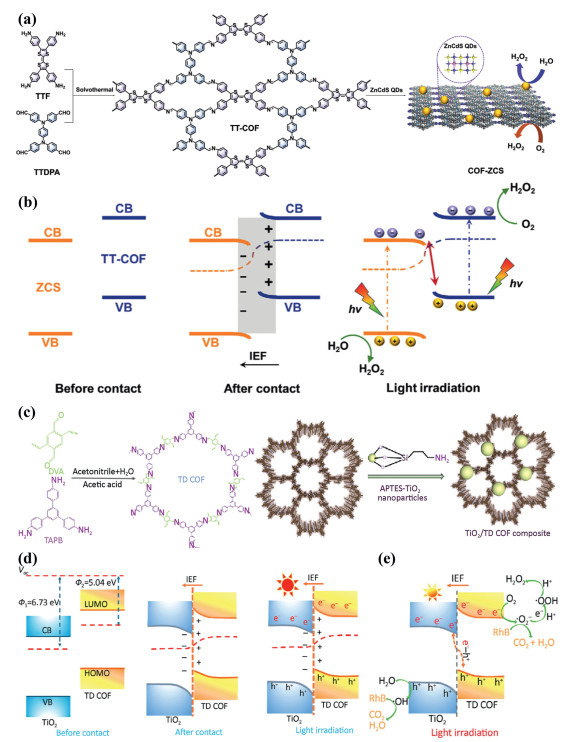
To expand the applications of COFs as reduction terminals, Zhao et al. engineered an S-scheme TiO2/TD COF heterojunction to clarify how interfacial Fermi-level mismatch drives charge redistribution and generates a built-in electric field, thereby governing carrier migration and selective cross-recombination (Fig. 4c) [103]. Upon contact in the dark, the higher Fermi level of TD COF induces electron transfer to TiO2, establishing interfacial band bending and a stable potential gradient (Fig. 4d). Under illumination, the built-in electric field and Coulombic interaction promote rapid recombination of electrons from the TiO2 CB with holes from the TD COF HOMO, while preserving the strongly reductive electrons in the TD COF LUMO and the oxidative holes in the TiO2 VB. This charge-separation behavior highlights the structure-dependent electronic function of the COF: its tailored energy levels and conjugated framework endow TD COF with efficient electron-delivery capability and reduction activity. Accordingly, TiO2 acts as the oxidation component, where photogenerated holes oxidize H2O to hydroxyl radicals (·OH), whereas TD COF functions as the reduction component, whose retained electrons reduce O2 to generate superoxide radicals (·O2–) and/or H2O2 (Fig. 4e). The generated ·OH and ·O2– contribute to RhB degradation, while the remaining ·O2– further supports H2O2 formation, resulting in a synergistic enhancement of pollutant degradation and photosynthetic H2O2 production.
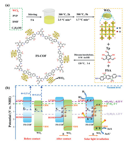
Moreover, the construction of the FS-COF/WO3 S-scheme heterojunction represents a sophisticated approach to band-structure engineering (Fig. 5a). By coupling the strongly reductive FS-COF with the oxidative WO3 semiconductor, Zhang et al. created a system where the disparate work functions dictate the interfacial electronic behavior [104]. The formation of the IEF is driven by the spontaneous migration of charges until the electrochemical potential reaches equilibrium, resulting in an electron-depletion region in the FS-COF and an electron-accumulation layer in the WO3 (Fig. 5b). This interfacial potential gradient facilitates the S-scheme charge transfer, where the low-energy charge carriers are rapidly annihilated at the interface. Crucially, this pathway ensures that the more reactive electrons and holes are spatially isolated and preserved for subsequent redox reactions. Consequently, this interfacial engineering strategy not only suppresses the recombination of photogenerated electron-hole pairs, while a common limitation in individual components, but also boosts the overall photocatalytic performance, providing a robust paradigm for designing high-efficiency hybrid photocatalytic systems.
Compared with conventional inorganic photocatalysts, COF-based hybrid systems assembled with organic counterparts offer distinct advantages for constructing S-scheme heterojunctions. Owing to their molecular-level programmability, tunable band structures, and structural diversity, COFs can be precisely integrated with complementary organic units to simultaneously optimize light harvesting, charge separation, and interfacial redox reactions. More importantly, such all-organic or organic-dominated heterostructures are often accompanied by stronger interfacial electronic coupling and more flexible structural compatibility than inorganic-based hybrids, making them highly favorable for building efficient S-scheme architectures.
For instance, Zhang et al. constructed a composite system comprising a near-infrared-absorbing metal-organic framework (CAT-1) and a covalent organic framework (COF-316), proposing an S-scheme heterojunction mechanism based on their well-aligned energy band structures (Fig. 6a) [105]. In this hybrid system, the structural features of COF-316, including its extended conjugation and efficient charge-generation capability, make it an effective light-harvesting component, while CAT-1 contributes active reaction sites and structural flexibility. The interfacial S-scheme configuration enhances charge transfer and mass transport, thereby accelerating photocatalytic kinetics. According to the work function and band structure calculations, electrons transfer from CAT-1 to COF-316 until Fermi level equilibration establishes a positively charged CAT-1, a negatively charged COF-316, and an IEF directed from CAT-1 to COF-316 (Fig. 6b). Upon illumination, this IEF induces band bending and Coulombic attraction, promoting the recombination of low-energy electrons in the COF-316 VB with holes in the CAT-1 VB while preserving the strongly reductive electrons in the CAT-1 CB and the strongly oxidative holes in the COF-316 VB. As a result, CAT-1 and COF-316 act as the oxidation and reduction terminals, respectively, enabling water oxidation and proton reduction. This S-scheme charge-transfer pathway improves charge separation and migration while retaining strong redox ability, thereby markedly enhancing photocatalytic performance.
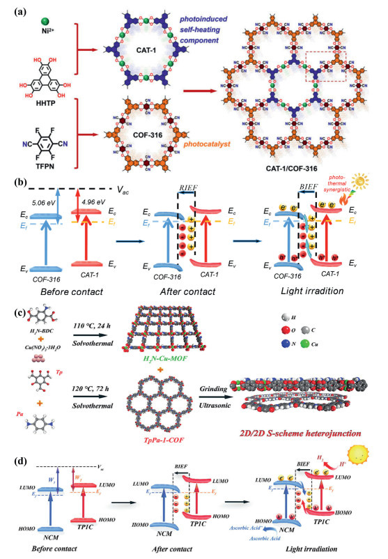
To improve photocatalytic efficiency, it is essential to design interfacial architectures that couple effective charge separation with strong redox preservation. Hu et al. constructed an S-scheme heterojunction, NCM/TP1C, by integrating an amine-functionalized Cu-MOF (NCM) with the TpPa-1 COF (TP1C) (Fig. 6c) and clarified its interfacial charge-transfer behavior through band structure and work function analyses [106]. Here, the ordered π-conjugated framework of TP1C enables efficient light harvesting and charge generation, making it a key photoactive component. After contact and Fermi-level equilibration, electrons migrate from TP1C to NCM, forming an IEF from TP1C to NCM (Fig. 6d). This IEF induces interfacial band bending and Coulombic attraction, driving the recombination of low-energy carriers at the interface while spatially separating high-energy carriers. As a result, electrons retained in the LUMO of TP1C preserve strong reductive power for H2 evolution, whereas holes remaining in the HOMO of NCM provide strong oxidative ability for sacrificial-agent consumption such as L-ascorbic acid. Thus, this S-scheme configuration enhances charge separation and migration while maintaining high redox potential, thereby markedly boosting photocatalytic activity.
Collectively, these studies indicate that the photocatalytic function of COFs in S-scheme heterojunctions is inseparable from their molecular structure, as the conjugated backbone, donor–acceptor character, and interfacial chemical environment jointly determine band alignment, charge separation, and redox selectivity. This structure–property relationship not only accounts for the versatile roles of COFs as oxidation or reduction terminals, but also provides a molecular basis for their further architectural optimization. On this basis, the next chapter will turn to the synthesis of COF-based S-scheme heterojunctions, with an emphasis on how fabrication strategies influence interfacial integration and photocatalytic performance.
The in-situ growth method involves the direct introduction of inorganic or organic semiconductor precursors onto COF precursors or their surfaces [107,108]. Conversely, π-π interactions originating from slipped-parallel stacking or non-coplanar tilted configurations can maintain the integrity of intrinsic porous networks, thereby optimizing the mass transport kinetics of reactants, albeit accompanied by attenuated interfacial electronic coupling [109-112]. This approach can be executed via one-step synchronous growth or step-by-step modulation strategies, allowing for the precise control over the morphology and distribution of the newly formed phase by systematically tuning parameters including precursor concentration, temperature, pH, reaction time, and solvent. As a specialized in-situ growth strategy, the co-precipitation method for constructing COF-based S-scheme heterojunctions typically involves the simultaneous introduction of COF precursors and inorganic/organic precursors into the same solution system. By meticulously designing the addition sequence and reaction conditions, this approach facilitates the synchronized nucleation and growth of both phases, thereby establishing an initial coupled state at the interface [113]. The essence of this strategy lies in the synergistic regulation of nucleation and growth kinetics through the precise control of solvent systems, pH, type and dosage of precipitating agents, temperature, stirring rate, and the stoichiometric ratio of the two precursors [114]. This collaborative process promotes the establishment of in-situ contact and interfacial adhesion between the COF framework and the secondary phase. Consequently, composites synthesized via the co-precipitation method typically exhibit favorable dispersibility, intimate interfacial coupling, and pre-formed chemical linkages, which facilitate dynamic interfacial modulation and the direct acquisition of structurally robust and highly ordered macroporosity without the need for post-synthetic processing.
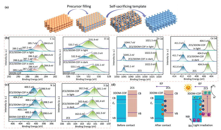
Under solvothermal conditions, Sun et al. synchronized the synthesis of the Tp-Tta COF with the degradation of a three-dimensionally ordered polystyrene template to fabricate the 3DOM-Tp-Tta COF [115]. Distinct from the dense porosity of conventional COFs, this material features a hierarchical micro–meso-macroporous architecture. Subsequently, via an in-situ co-precipitation method, fine ZnCdS (ZCS) nanoparticles were uniformly dispersed onto the 3DOM-Tp-Tta COF, successfully constructing a COF-based S-scheme heterojunction (ZCS/3DOM-COF) endowed with a three-dimensionally ordered macroporosity (3DOM) structure (Fig. 7a). The ZCS nanoparticles are anchored at the pore centers of the 3DOM-Tp-Tta COF. The in-situ co-precipitation within this confined pore space restricts both nucleation and growth, ensuring that the ZCS nanoparticles form primarily at the pore centers and are enveloped by the COF framework. This spatial confinement effectively mitigates agglomeration and enhances dispersibility; furthermore, this intra-pore growth mode is highly conducive to forming expansive contact areas and continuous interfaces. Under illumination, the binding energies of C 1s, N 1s, and O 1s in the 3DOM-COF shift toward higher energy states, whereas those of Zn 2p, Cd 3d, and S 2p in ZCS shift toward lower energy states, confirming the formation of a S-scheme charge transfer mechanism (Figs. 7b and c). Consequently, the synergistic effect of the 3DOM architecture and the S-scheme construction modulates the band structure of the heterojunction, achieving favorable band alignment. The Fermi level mismatch induces an internal electric field, which accelerates hole diffusion and the targeted interfacial recombination of useless charge carriers, thereby realizing rapid and efficient carrier separation (Fig. 7d). Simultaneously, this optimal energy level matching lowers the activation energy barrier for benzylamine and optimizes the reaction thermodynamics, endowing the composite with exceptional activity and selectivity in both benzylamine oxidation and hydrogen evolution reactions. From a broader perspective, the hybridization of COFs with secondary phases via co-precipitation strategies facilitates the precise modulation of their textural properties, including pore size distribution, pore volume, and channel topology by precisely controlling the type, proportion, and local coordination environment of the inorganic components, researchers can achieve the directional design of pore connectivity and porous architecture. This strategy significantly enhances the specific surface area, porosity, and the selective adsorption and mass transport capacities for target molecules, demonstrating immense application potential for strengthening interfacial coupling, facilitating charge transport, and advancing the overall performance of S-scheme heterojunctions.
Layer-by-layer (LbL) assembly is a strategy that enables the controllable construction of ordered multilayer interfaces at the molecular-to-nanoscale level via the alternating deposition or in-situ growth of distinct organic/inorganic units or COF layers on substrates [116]. This process can be implemented through various LbL techniques, such as spontaneous deposition, ultrasonic exfoliation-dispersion, or solvent evaporation-induced assembly [117]. Consequently, nanofilms or exfoliated COF nanosheets can be fabricated, driven by underlying mechanisms including electrostatic self-assembly, π-π stacking, coordination-driven assembly, or covalent bonding. By precisely arranging donor-acceptor layers and modulating energy-level alignments alongside interfacial work functions, charge transport channels that satisfy S-scheme requirements can be established at the interface. This configuration significantly promotes the spatial separation and directional migration of photogenerated electron-hole pairs, thereby enhancing the utilization efficiency of respective reduction or oxidation active sites. Furthermore, LbL assembly permits the systematic tuning of bandgaps and charge-carrier transport properties by controlling the stacking modes, which directly influences π-π interactions, interlayer spacing, and pore size distributions. Furthermore, it enables the orchestration of multiscale interfacial coupling, encompassing a broad spectrum of interactions ranging from electrostatic and π-π interactions to directional coordination or covalent bonds. Through rational component selection and post-treatment strategies (e.g., cross-linking or the introduction of coordination sites), the interfacial binding strength and electronic coupling can be finely modulated, achieving an optimal balance between catalytic activity and structural robustness. In COF-based S-scheme systems, interfacial electronic coupling dictates the separation efficiency and migration pathways of photogenerated charge carriers, which fundamentally govern the overall photocatalytic kinetics and selectivity. Consequently, it is imperative to adopt tailored synthetic strategies to construct COF-based S-scheme heterojunctions with specific interfacial interactions customized for targeted applications.
Electrostatic self-assembly enables the ordered integration of COFs with other functional units in solution or at interfaces, driven by Coulombic attraction between oppositely charged components [118,119]. This methodology can be implemented via either one-step mixing or LbL assembly, offering distinct advantages in terms of operational simplicity, structural controllability, and scalability. However, COF-based S-scheme heterojunctions synthesized via electrostatic assembly often suffer from weak interfacial adhesion due to the reliance on non-covalent interactions, frequently necessitating supplementary stabilization strategies such as cross-linking, thermal annealing, or in-situ growth [120,121]. Notably, interfacial electrostatic accumulation can generate localized electric fields and charge gradients, which facilitate directional carrier transfer, thereby establishing an S-scheme migration pathway and significantly enhancing the separation efficiency of photogenerated charge carriers [122,123].
Within the LbL self-assembly framework, the specific utilization of π-π stacking provides a highly controllable and modular pathway for constructing COF-based S-scheme heterojunctions. Through sequential layer deposition or interface-induced assembly, π-π stacking and interfacial coupling can be precisely regulated between distinct COF thin layers, thereby establishing large-area, intimate, and continuous 2D/2D contact interfaces. This structural precision facilitates the synergistic tuning of interfacial energy levels and Fermi level misalignment, which induces a robust built-in electric field at the interface to promote the directional migration and efficient separation of photo-generated electron-hole pairs [124,125]. Concurrently, the extension of interfacial π-conjugation and the subsequent redshift of the absorption spectrum significantly enhance visible-light harvesting and the generation of photo-excited carriers. Furthermore, the inherent controllability of the LbL approach allows for the targeted introduction of defect sites or co-catalytic components, effectively optimizing reactant adsorption/activation and interfacial charge transfer dynamics. Consequently, this strategy offers a reproducible, modular, and highly scalable technological platform for the fabrication of organic-based S-scheme photocatalytic heterojunctions with superior selectivity and catalytic activity.
Coordination-driven self-assembly is fundamentally predicated upon the establishment of directional coordination linkages between metallic precursors and targeted electron-donating organic motifs embedded within the COF scaffold, including pyridinic, carbonyl, amino, or hydroxyl functionalities [126]. This mechanism effectively anchors metals, metal oxides, or their respective nanoparticles onto the surfaces or within the porous channels of the COFs. Driven by these coordination interactions, an ordered, layer-by-layer interfacial assembly and in-situ growth are realized, thereby promoting interlayer binding and spontaneous stacking between the COF scaffold and the coordinated species [127,128]. Crucially, this structural integration induces a redistribution of local electron density, which subsequently alters the surface work functions of the COFs and the metal-containing counterparts. As a result, a robust built-in electric field is established at the hetero-interface, driving the formation of an S-scheme heterojunction. This interfacial electronic modulation ultimately broadens the visible-light absorption spectrum and significantly optimizes the generation efficiency of photo-excited electron-hole pairs.
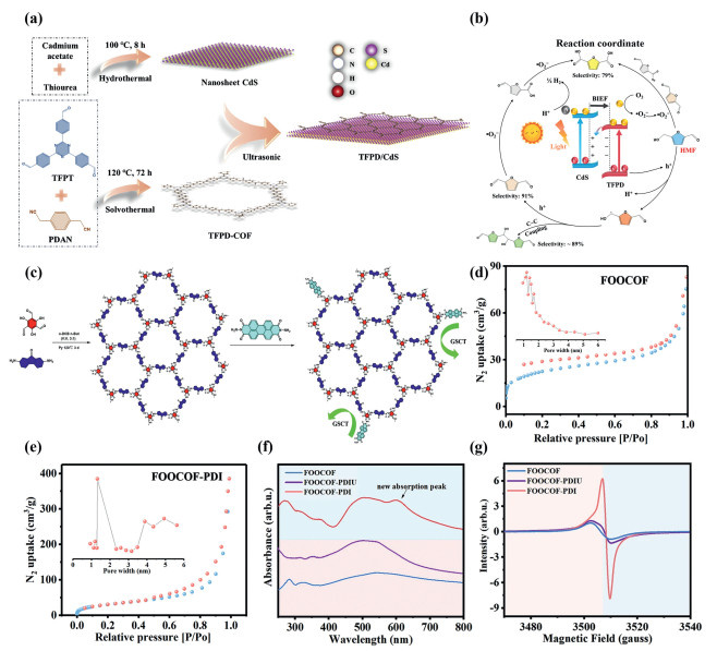
To achieve a significant enhancement in the photocatalytic performance of COF-based S-scheme heterojunctions, Qi et al. implemented a synergistic strategy coupling electrostatic self-assembly with in-situ growth to precisely engineer the interfacial microstructure and maximize carrier migration efficiency [129]. Specifically, CdS and the specific COF (TFPD) were first synthesized via independent solvothermal routes, and subsequently integrated through ultrasonication-assisted assembly to construct a hierarchically layered TFPD/CdS composite (Fig. 8a). Driven by favorable band alignment and a robust interfacial built-in electric field, the resulting TFPD/CdS heterojunction exhibited significantly enhanced charge separation, which was evidenced by an augmented photocurrent response, diminished charge transfer resistance, and prolonged charge carrier lifetimes. The accelerated hole transfer kinetics, coupled with the extended carrier longevity, facilitated the preferential adsorption of 5-hydroxymethylfurfural (HMF) molecules onto the TFPD surface. Subsequent interactions with photogenerated holes yielded (CHOH)C4H2(CHO)· radicals and protons (Fig. 8b). The dynamic adsorption-desorption behavior of these radical intermediates governed the selective conversion of HMF, thereby achieving highly efficient hydrogen evolution synergistically coupled with the generation of value-added chemicals. Furthermore, coupling electrostatic self-assembly with in-situ growth strategies enables the layer-by-layer integration of COFs and inorganic compounds. Subsequent in situ thermal curing facilitates robust chemical bonding between the components, culminating in a tightly coupled and highly stable interfacial architecture.
In the context of COF-based S-scheme heterojunctions, covalent grafting refers to the direct establishment of stable covalent linkages (e.g., C–C, C–N, C–O) or conjugated bridging moieties between adjacent layers or disparate functional units. By superseding labile non-covalent interactions which include van der Waals forces, π-π stacking, and hydrogen bonding that this methodology engenders robust, anisotropic, and irreversible atomic-scale connectivity under facile synthetic protocols [131,132]. Structurally, such covalent interlayer coupling eliminates interfacial gaps, minimizes interfacial resistance, and bolsters overall structural integrity [133]. Electronically, it broadens the optical response via the introduction of hybrid energy levels or bandgap restructuring; furthermore, the resultant valence orbital overlap and extended conjugation significantly strengthen interfacial electronic coupling. This facilitates the formation of S-scheme band alignments and promotes the directional injection and separation of photogenerated carriers, thereby enhancing both photocatalytic activity and cyclic stability. A specialized manifestation, covalent single-molecule junction grafting, involves the site-specific anchoring of individual molecular units onto the COF skeleton through strong interactions. These constructs provide controlled, nanoscale electron-transport channels and localized chemical sites that facilitate ground-state charge transfer. Nevertheless, the integration of inappropriate covalent motifs or an immoderate grafting degree can trigger the formation of electronic trap states and unfavorable band offsets, which collectively compromise the redox potency of the photocatalyst. Simultaneously, the steric occlusion of the framework’s intrinsic channels and the resulting loss of porosity can severely hamper reactant diffusion kinetics, ultimately offsetting the advantages of covalent functionalization. Consequently, the judicious selection of bond types and grafting sites is paramount to optimizing light harvesting, facilitating S-scheme carrier dynamics, and maximizing photocatalytic efficiency.
To minimize the interfacial charge transfer barrier and establish atomic-level continuous channels for charge carrier transport, Shen et al. employed a covalent grafting strategy to construct a 3D-stacked S-scheme heterojunction, FOOCOF-PDIU [130]. Specifically, a terminal aldehyde-functionalized COF (FOOCOF) was synthesized via solvothermal conditions and subsequently anchored to amine-terminated perylene diimide (PDINH) through imine linkage formation, effectively facilitating seamless charge migration across the heterojunction interface. By employing a distinct covalent linkage strategy, the authors successfully transformed the 3D stacked architecture into a coplanar, single-molecule junction, designated as FOOCOF-PDI (Fig. 8c). Comparative analyses against the 3D-stacked precursor and pristine FOOCOF revealed that, despite a marginal decrease in Brunauer–Emmett–Teller (BET) surface area and preserved pore size distribution, the FOOCOF-PDI system exhibited significantly enhanced thermal stability (Figs. 8d and e). Spectroscopic and magnetic characterizations reveal that FOOCOF-PDI exhibits a distinct charge-transfer (CT) absorption feature in the UV–vis spectrum (Fig. 8f), alongside a pronounced dark-state signal in electron spin resonance (ESR) measurements (Fig. 8g), unambiguously validating the occurrence of ground-state charge transfer (GSCT). This intensified GSCT reconfigures the spatial and energetic landscape, inducing a dipole moment and strengthening the built-in electric field, which collectively facilitate exciton dissociation, promote free carrier generation, and extend carrier lifetimes, ultimately leading to a substantial boost in photocatalytic hydrogen evolution activity. Covalent grafting, including the formation of single-molecule junctions, serves as a powerful interfacial engineering strategy at the molecular scale. By constructing stable covalent linkages, this approach enables precise modulation of interfacial energy-level alignment, local dipole moments, and charge density distribution. Such covalent integration optimizes electronic coupling and strengthens the built-in electric field, effectively lowering charge-transfer impedance and promoting exciton dissociation to yield long-lived charge carriers, thereby enhancing photocatalytic performance and selectivity. Nevertheless, the performance gains are critically dependent on the bonding chemistry, grafting topography, and grafting density, all of which are modulated by the interplay between molecular configuration and the local electronic environment. Consequently, realizing optimal interfacial functionalization requires a holistic methodology that combines precise ligand engineering and controlled grafting layouts with comprehensive spectroscopic characterization and computational modeling.
In COF-based S-scheme heterojunction systems, the interface dictates the energy-level alignment of electrons and holes, the direction and strength of the built-in electric field, the kinetics of charge-carrier transport and recombination, as well as the separation and migration pathways of photogenerated charges across the phase boundary [134,135]. A comprehensive assessment of interfacial attributes, such as electronic band alignment, chemical linkages, surface states, charge density, potential profiles, and photoinduced carrier kinetics, is essential for delineating the fundamental constraints on charge-carrier separation and migration [136,137]. Furthermore, quantifying potential barriers and electric field orientations provides critical feedback for the rational design of materials, such as the optimization of functional groups, doping strategies, interfacial modification, and interlayer orientation [138]. Such a feedback loop is pivotal for enhancing charge separation efficiency, prolonging carrier lifetimes, suppressing recombination, and ultimately boosting photocatalytic reaction rates, quantum efficiency, and long-term stability. Conventional and in-situ X-ray photoelectron spectroscopy (XPS) serves as direct probes for elucidating the chemical states of interfacial elements and their corresponding binding energy shifts [139], thereby providing primary experimental evidence for interfacial interactions and band alignment. Building upon this, Kelvin probe force microscopy (KPFM, including photo-excited KPFM) [140], enables the simultaneous acquisition of topography, contact potential difference (CPD), and photo-induced potential responses at the nanoscale. This allows for a direct visualization of how interfacial interactions induce band bending and localized built-in electric fields influence charge-carrier spatial distribution and separation efficiency. Furthermore, the synergistic application of femtosecond transient absorption spectroscopy (fs-TAS) and TRPL provides time-resolved insights into carrier dynamics [141,142], facilitating the quantitative differentiation between interfacial charge transfer and recombination processes, as well as the determination of charge transport kinetics. Finally, density functional theory (DFT) calculations offer microscopic insights into electronic band structures [143,144], interfacial charge redistribution, and migration barriers, providing semi-quantitative estimates of carrier lifetimes and their subsequent impact on photocatalytic activity. The following sections will provide a detailed overview of these characterization techniques.
XPS utilizes X-ray photon irradiation to induce the emission of core-level electrons from the near-surface region of a sample. By measuring the kinetic energy of these photoelectrons, the binding energy (
|
|
In this equation,
Conventional XPS typically involves ex-situ analysis, where samples are characterized under static high-vacuum conditions after being removed from their synthesis or reaction environments. By acquiring high-resolution narrow-scan spectra, researchers can extract critical information regarding chemical binding energies, peak morphologies, and integrated intensities, thereby elucidating variations in local electron density, chemical bonding environments, and oxidation states. In contrast, in-situ XPS affords real-time monitoring under operational conditions, such as specific illumination, controlled gas environments, or thermal stimuli, enabling the collection of high-resolution spectra with high temporal resolution to track transient surface phenomena [146]. This technique facilitates the direct observation of dynamic evolutions in binding energies (
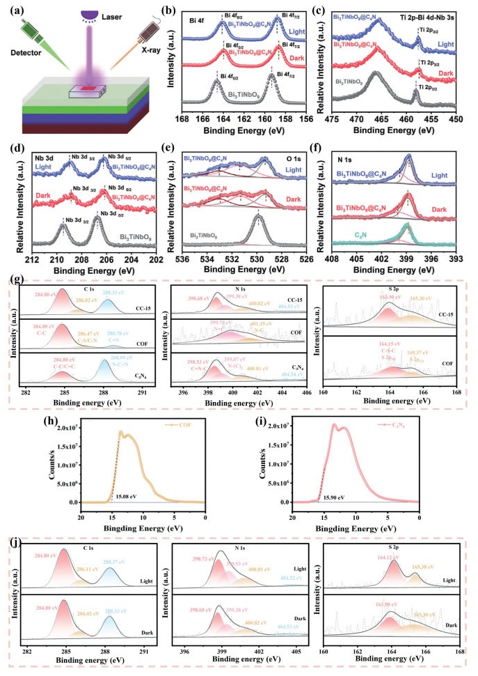
To unveil the interfacial charge transfer pathway, Teng et al. utilized in-situ XPS to investigate the interfacial interactions and charge transfer mechanisms within the Bi3TiNbO9@C4N heterojunction under both dark and illuminated conditions (Figs. 9a-f) [147]. In the dark, the Bi 4f spectrum showed Bi 4f7/2 and Bi 4f5/2 peaks at 158.66 and 163.97 eV, respectively; the Ti 2p peak at 457.42 eV confirmed Ti4+ species; and the Nb 3d peaks at 206.15 and 208.87 eV were consistent with Nb2O5. The O 1s spectrum was deconvoluted into three components at 529.23, 531.30, and 532.93 eV, assigned to lattice oxygen, carbonate species, and adsorbed H2O or surface –OH groups, respectively, while the N 1s spectrum exhibited peaks at 398.83 and 400.00 eV, corresponding to residual –NH2 groups and pyrazine-like N–C species. Upon 405 nm irradiation, the Bi 4f, Ti 2p, Nb 3d, and O 1s peaks shifted positively by approximately 0.15, 0.20, 0.10, and 0.10 eV, respectively, indicating reduced electron density, whereas the N 1s peak shifted negatively by about 0.20 eV, evidencing photoinduced interfacial charge redistribution. These results support an S-scheme charge transfer process, in which photogenerated electrons migrate from Bi3TiNbO9 to C4N under illumination. Notably, no direct spectroscopic evidence for Bi–N coordination was observed, likely due to the low abundance of Bi–N bonds associated with localized C/N coordination effects. Overall, the in-situ XPS analysis provides direct insight into the interfacial electronic dynamics of this COF-based S-scheme heterojunction, highlighting directional carrier migration, charge reconstruction, and enhanced charge separation upon photoexcitation. Another, Liu et al. employed ex-situ high-resolution XPS (C 1s, N 1s, and S 2p) to quantitatively identify the surface elements and chemical states of C3N4, the COF, and their composite (CC-15), utilizing chemical shifts to elucidate the redistribution of electron density upon composite formation [148]. As illustrated in Fig. 9g, the characteristic peaks associated with the COF shifted toward lower binding energies (indicating increased electron density), whereas those associated with C3N4 shifted toward higher binding energies (indicating decreased electron density), signifying a static redistribution of electrons from C3N4 to the COF in the dark state. Furthermore, work functions (φ) calculated from the secondary electron cutoff (Ecutoff) via ultraviolet photoelectron spectroscopy (UPS) (φ = 21.22 – Ecutoff) revealed values of approximately 5.32 eV and 6.14 eV for C3N4 and the COF, respectively (Ecutoff values of 15.90 and 15.08 eV) (Figs. 9h and i). This energy offset implies that the Fermi level of C3N4 lies above that of the COF, driving the spontaneous migration of free electrons from C3N4 to the COF upon contact, thereby establishing interfacial charge accumulation and an internal electric field. In-situ XPS measurements, by comparing binding energy shifts at identical sites under dark and illuminated conditions, directly revealed transient photoexcited electron redistribution (Fig. 9j). Under illumination, the C 1s, N 1s, and S 2p spectral components of the C3N4/BUCT-COF heterojunction (CC-15) exhibited subtle shifts, indicating a light-induced electron migration from the COF to C3N4. This direction is opposite to the static electron migration inferred from dark-state UPS, confirming the establishment of Fermi level equilibration and an internal electric field in the dark, which are characteristic features of an S-scheme heterojunction. This mechanism facilitates the cross-interface recombination of high-energy electrons and low-energy holes, effectively preserving electrons with strong reducing power and holes with strong oxidizing power in the respective phases.
Consequently, the quantitative analysis of high-resolution peak positions and chemical shifts enables XPS to identify variations in elemental valence states and the formation or cleavage of chemical bonds, thereby elucidating the electron donor/acceptor behavior of heterojunctions or adsorbed species at interfaces. By integrating in-situ and ex-situ measurements, it is possible to dynamically track valence state evolution, carrier trapping/release processes, and the formation of reaction intermediates under illumination or reaction conditions. This approach provides direct chemical evidence essential for understanding carrier separation efficiency, the chemical environment of active sites, and catalytic selectivity.
KPFM, an AFM-based scanning probe technique, directly resolves interfacial surface potential differences, local work functions, charge accumulation/depletion regions, interfacial dipoles, and charge-transfer directions between COFs and semiconductors, thereby addressing key interface-science questions related to band alignment, carrier injection barriers, and photogenerated carrier dynamics. Because these quantities are closely coupled to carrier separation, transport, and recombination, KPFM provides a quantitative means to compare different contact configurations. Chemical bonding typically induces pronounced electron-density redistribution and rigid interfacial dipoles, which appear as stable surface-potential steps or spatial potential gradients in KPFM maps [149,150]. By contrast, non-covalent interactions generally produce smaller potential shifts, localized potential hotspots, or time-dependent signals with stronger photo-responsivity. Interfaces formed through covalent or coordination bonding usually exhibit stronger electronic coupling, larger contact potential differences, and extended depletion/accumulation regions, favoring directional migration of photogenerated electrons/holes. Moreover, monitoring surface-potential changes and light-switching responses under illumination enables assessment of carrier generation, lifetime, and migration pathways [151,152]. In this context, covalent interfaces often show faster light-induced potential buildup and slower decay, consistent with more efficient charge separation and trapping, whereas non-covalent interfaces tend to display weaker or more rapidly relaxing photoinduced signals. Overall, KPFM offers a powerful quantitative window into interfacial electronic coupling and carrier dynamics, making it especially valuable for evaluating and optimizing COF-based S-scheme heterojunctions.
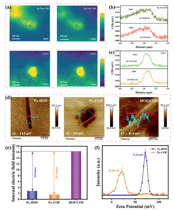
To elucidate the charge transfer characteristics of the heterocatalytic system composed of Tp-Tta COF and MoS2 (CM-9), Li et al. employed KPFM to characterize the surface potential of the materials under both dark and illuminated conditions [153]. As illustrated in Figs. 10a-c, the CM-9 composite exhibited a more pronounced surface potential heterogeneity in the dark state, with a measured potential difference (ΔE) of 47.21 mV, whereas the pristine Tp-Tta COF displayed a weaker potential contrast (ΔE = 26.89 mV). Upon illumination, the surface potentials of both catalysts increased significantly; however, the MoS2-modified CM-9 composite demonstrated a notably higher ΔE (50.13 mV) compared to the pristine Tp-Tta COF (29.18 mV). Based on these KPFM data, the authors proposed that the internal electric field within the heterojunction facilitates the directional migration of photogenerated charges from the Tp-Tta COF to the MoS2 sites. This migration results in the accumulation of photogenerated holes from the bulk to the surface of the Tp-Tta COF, thereby inducing a significant enhancement in its surface potential. These findings provide compelling evidence for the existence of an interfacial electric field that promotes charge separation and transport, which effectively accounts for the markedly improved photocatalytic activity of the CM-9 system. By integrating in-situ KPFM characterization with surface charge density and zeta potential measurements, Gao et al. quantitatively elucidated how the intensity and spatial distribution of the IEF within a heterojunction influence charge separation and directional transport [154]. Specifically, KPFM measurements reveal that the surface potential difference (ΔE) of the HOF/COF heterojunction (40.0 mV) is significantly higher than those of its pristine counterparts, Py-HOF (14.8 mV) and Py-COF (9.0 mV) (Fig. 10d). Subsequent normalized analysis demonstrates that the resulting IEF intensity within the heterojunction is 5.8- and 10.1-fold greater than those of isolated Py-HOF and Py-COF, respectively (Fig. 10e). Furthermore, zeta potential measurements of the individual components reveal a pronounced surface charge disparity between Py-HOF (71.16 mV) and Py-COF (22.00 mV) (Fig. 10f), which strongly corroborates the KPFM observations. Collectively, these elevated surface and zeta potentials substantiate the formation of a robust IEF at the heterointerface, which acts as a powerful driving force for the efficient spatial separation and directional migration of charge carriers.
In summary, the spatial potential distribution provided by KPFM, combined with the macroscopic charge states reflected by surface charge density and zeta potential measurements, provides a direct and quantitative characterization of the intensity and orientation of the interfacial electric field within heterojunctions. Collectively, these findings offer robust experimental evidence to elucidate the mechanisms underlying enhanced carrier separation efficiency and the selection of charge transport pathways.
COFs offer highly tunable optical bandgaps and charge-transport properties, making them attractive components of S-scheme heterojunctions with staggered band alignment for efficient carrier separation. In this context, fs-TAS provides a direct time-resolved probe of the interfacial charge dynamics that govern photocatalytic performance, capturing excited-state generation, separation, energy transfer, and recombination from sub-picoseconds to beyond picoseconds [155]. By quantifying the lifetimes of separated states, interfacial injection/re-injection rates, and cross-interface energy-transfer channels under different bonding configurations, fs-TAS reveals how interfacial coupling strength and band alignment regulate carrier migration across the junction. Bonding modes that promote directional electron/hole separation typically give rise to rapid signal buildup and long-lived transient species, whereas fast interfacial recombination is reflected in shortened separated-state lifetimes [156]. Strongly coupled interfaces often display distinct transient absorption features associated with electron or hole transfer, with the emergence, evolution, and decay of signals at specific wavelengths tracking interfacial transport barriers and kinetics. Through global fitting of time constants and weighting parameters, fs-TAS establishes a quantitative link between microscopic carrier behavior and macroscopic photocatalytic activity, offering critical kinetic insight for the rational design of high-performance COF-based heterojunctions.
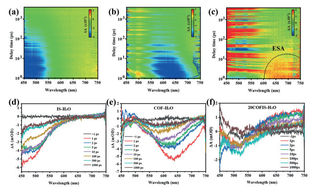
To investigate the charge carrier dynamics of the material, Qiu et al. employed 400 nm-pumped fs-TAS to perform wavelength-time coupled characterization of the photogenerated carrier dynamics in IS, COF, and their 20COFIS composite, directly elucidating the microscopic mechanisms of carrier injection and recombination (Figs. 11a-f) [157]. In the pristine IS, a characteristic negative signal observed at approximately 500 nm was attributed to ground-state bleaching (GSB). Conversely, the pristine COF exhibited a broad negative band in the 500–750 nm range (with a primary peak at ~635 nm), which corresponds to the superposition of GSB and stimulated emission (SE), consistent with its steady-state photoluminescence (PL) profile. Scavenger experiments further corroborated these findings: the addition of the electron acceptor K2Cr2O7 resulted in the complete quenching of the fs-TA signals for both IS and COF, whereas the hole scavenger (ethanol) exerted negligible influence. This provides chemical evidence that the observed dynamics are primarily driven by photogenerated electron transfer. In the 20COFIS composite, a significant suppression of the COF-related GSB/SE signals was observed, accompanied by the emergence of a new positive signal in the 650–750 nm region, attributed to excited-state absorption (ESA). In the context of an S-scheme charge transfer mechanism, this can be rationalized by the rapid migration of photogenerated electrons from the conduction band of the COF to the valence band of the IS for recombination. Furthermore, the interfacial coupling is suggested to induce hybrid energy levels, which account for the appearance of the ESA signal and the broadened optical absorption range of the composite.
Therefore, by leveraging the femtosecond-to-picosecond temporal resolution and broadband spectral resolution of fs-TAS, it is possible to simultaneously capture the injection, migration, and recombination dynamics of photogenerated carriers in heterojunctions across both temporal and spectral domains, thereby providing direct kinetic evidence for constructing and validating S-scheme charge transfer mechanisms.
By resolving electron density, band structures, and energy barriers from first principles, DFT can quantitatively reveal the impacts of distinct interfacial bonding modes on electronic coupling, local charge redistribution, vacuum level shifts, and energy level alignment. Specifically, DFT provides comparable microscopic quantitative indicators for chemical bonding and non-covalent contacts in terms of charge transfer magnitude, work function variations, density of states (DOS) reconstruction, and cross-interface carrier migration barriers. These parameters are directly correlated with the separation efficiency of photogenerated carriers, cross-interface transfer kinetics, and the adsorption/activation energies of catalytic intermediates [158]. Furthermore, by integrating DOS/projected DOS (PDOS) analysis, charge density difference maps (Δρ), Bader charge analysis, nudged elastic band (NEB) migration pathways, and excited-state calculations (TD-DFT), these theoretical approaches offer mechanistic and predictive design guidelines for the screening and optimization of bonding strategies in COF-based S-scheme heterojunctions.
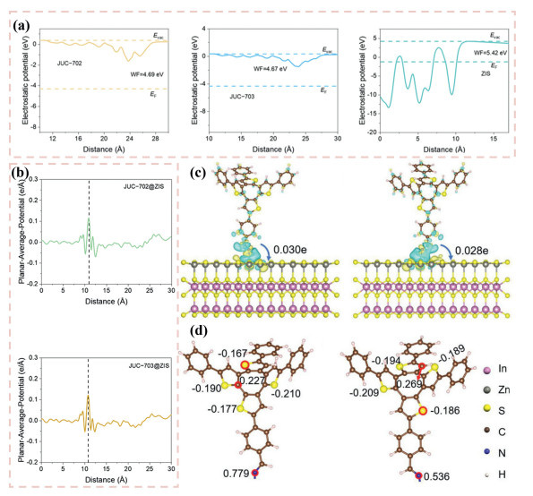
To visualize the charge distribution, Zhang et al. engineered a series of JUC-X/ZnIn2S4 (ZIS) heterojunctions by utilizing cyclotetrathiophene (COTh) isomers with distinct sulfur atom configurations as building blocks, systematically evaluating their photocatalytic hydrogen evolution performance [159]. The presence of electron-rich thiophene moieties and tunable π-conjugated frameworks within the COFs significantly facilitates charge carrier separation and transport. To identify the optimal adsorption and reaction sites for hydrogen evolution and elucidate the interfacial charge transfer mechanism, the work functions of the individual components were evaluated both experimentally and via DFT calculations. The results revealed that the work function of ZIS is higher than those of JUC-702/703 (Fig. 12a), dictating that upon heterojunction formation, electrons spontaneously flow from JUC-X to ZIS to achieve Fermi level alignment. This process is accompanied by the reverse migration of holes, thereby establishing a built-in electric field at the interface. Corresponding charge density difference maps provided direct visual confirmation of this directional electron transfer (Fig. 12b). Concurrently, pronounced variations in atomic charges and adsorption energies signify interfacial charge redistribution and the generation of an internal molecular electric field (Figs. 12c and d). Furthermore, the extended π-conjugation and highly asymmetric charge distribution within the COFs drive photogenerated electrons to preferentially migrate toward the COTh-1–4CHO units, ultimately enhancing both the selectivity and activity of the hydrogen evolution reaction (HER).
In summary, DFT calculations are indispensable in the study of COF-based S-scheme heterojunction photocatalysts, providing critical insights into interfacial energy levels, DOS, and orbital compositions. This theoretical framework enables the determination and elucidation of the thermodynamic migration directions and driving forces of photogenerated charge carriers. Furthermore, the computation of charge density differences, Bader charges, and electrostatic potential distributions intuitively delineates interfacial charge redistribution and the formation of built-in electric fields. These analyses allow for the precise identification of electron/hole enrichment centers and optimal adsorption/reaction sites, thereby offering actionable design principles for energy-band engineering and interfacial tailoring to drive the rational optimization of photocatalytic systems.
In COF-based S-scheme heterojunctions, the interface determines critical parameters such as the accuracy of band alignment, the intensity of the internal electric field, interfacial resistance, and the generation of active sites [160]. Consequently, it profoundly influences the separation efficiency, lifetime, and transport velocity of photogenerated carriers, along with the reaction kinetics at the actual catalytic sites. Interfacial engineering enables the efficient and directional separation and transport of photogenerated carriers, suppresses electron–hole recombination, and optimizes band alignment, thereby significantly enhancing visible-light-driven photocatalytic activity and stability [161]. Specifically, the formation of interfaces via non-covalent interactions (e.g., van der Waals forces and π-π stacking) or covalent linkages can effectively reduce charge-transfer resistance, prolong carrier lifetimes, and improve both light absorption and the exposure of surface active sites [162-165]. Consequently, this boosts photocatalytic efficiency and reaction selectivity by elevating carrier separation efficiency, accelerating migration, and increasing the accessibility of catalytic sites. Ultimately, these interfacial interactions dictate the electron-hole coupling strength, interfacial energy-level alignment, and interface trap states, which directly govern the separation and transport kinetics of photogenerated carriers, their recombination behaviors, and the overall photocatalytic activity (Table 1).

 DownLoad:
CSV
| Interface interaction | Interfacial coupling strength | Synthesis strategy | Heterojunctions | Application and reduction rate (µmol g–1 h–1) | Refs. | |
| Van der Waals interactions | Low to medium | Layer-by-layer self-assembly | Pt-CdS-5% TBADF | H2: 127,270.0 in L-ascorbic acid solution | [101] | |
| Van der Waals interactions | Low to medium | In-situ growth | FS-COF/WO3–20% | H2: 24,700.0 in L-ascorbic acid solution | [104] | |
| Van der Waals interactions | Low to medium | Layer-by-layer self-assembly | TFPD/CdS-2:8 | H2: 228.7 in aqueous solutions containing 0.01 mol/L biomass | [129] | |
| Van der Waals interactions | Low to medium | Layer-by-layer self-assembly | CC-15 | H2: 1121.8 in triethanolamine solution | [148] | |
| Van der Waals interactions | Low to medium | In-situ growth | CM-9 | H2: 12,500.0 in triethanolamine solution | [153] | |
| Van der Waals interactions | Low to medium | In-situ growth | Mo0.01-ZIS/TpPa-1 | H2: 1648.0; N-benzylidenebenzylamine: 1812.0 in benzylamine solution | [214] | |
| Van der Waals interactions | Low to medium | In-situ growth | TZ-40 | H2O2: 5171.0 in water | [102] | |
| Van der Waals interactions | Low to medium | In-situ growth | 10% TpMA/In2S3 | H2O2: 691.27 in water | [202] | |
| Van der Waals interactions | Low to medium | In-situ growth | 20BTB | H2O2: 1088.46 in ethanol solution | [203] | |
| Van der Waals interactions | Low to medium | Layer-by-layer self-assembly | g-C3N4 (NH)/COF | CO: 562.5 in triethanolamine (maximum value) | [170] | |
| Van der Waals interactions | Low to medium | Layer-by-layer self-assembly | COF/QDs-Ⅱ | CO: 41.2; | [209] | |
| CH4: 13.7 | ||||||
| Van der Waals interactions | Low to medium | In-situ growth | COF/ZnSe-1 | CO: 128.3 in 1-phenylethanol solution | [215] | |
| π-π interactions | Medium | Layer-by-layer self-assembly | TPCNNS-2 | H2: 1153 in sodium ascorbate solution | [174] | |
| π-π interactions | Medium | Layer-by-layer self-assembly | TpBD COF@ZIS-10 | H2: 2304 in L-ascorbic acid solution | [175] | |
| π-π interactions | Medium | Layer-by-layer self-assembly | 20% NCM/TP1C | H2: 4190.0 in L-ascorbic acid solution | [106] | |
| π-π interactions | Medium | Layer-by-layer self-assembly | Py-HOF/Py-COF (6:1) | H2: 390,680.0 in L-ascorbic acid solution (maximum value) | [154] | |
| Chemical bonds | Coordination bonds | Medium to high | In-situ growth | 4% COF-ZIS | H2: 695.0 in Na2S/Na2SO3 solution | [100] |
| Chemical bonds | Coordination bonds | Medium to high | In-situ growth | ZCS/3DOM-COF | H2: 17,800.0 in benzylamine solution | [115] |
| Chemical bonds | Coordination bonds | Medium to high | In-situ growth | JUC-704@ZIS (1:8) | H2: 9460.0 in seawater | [159] |
| Chemical bonds | Coordination bonds | Medium to high | In-situ growth | CZS-2mgFOCTF | H2: 247,620.0 in L-ascorbic acid solution | [200] |
| Chemical bonds | Coordination bonds | Medium to high | In-situ growth | Bi3TiNbO9@C4N | H2O2: 1250.0 in water | [147] |
| Chemical bonds | Coordination bonds | Medium to high | In-situ growth | 20COFIS | H2O2: 5713.2 in water (maximum value) | [157] |
| Chemical bonds | Coordination bonds | Medium to high | In-situ growth | PyTdCdS5 | H2O2: 3930 in 1,4-benzenedimethanol solution | [181] |
| Chemical bonds | Coordination bonds | Medium to high | In-situ growth | BTC40 | H2O2: 3749 in 10 vol% ethanol solution | [182] |
| Chemical bonds | Coordination bonds | Medium to high | In-situ growth | CCZS-0.6 | H2O2: 53.6 in pure water | [201] |
| Chemical bonds | Coordination bonds | Medium to high | In-situ growth | Zr-BTB-COF-3 | CO: 71.9; Anisaldehyde: 44.7 in ethylene glycol and ethanol mixed solution | [180] |
| Chemical bonds | Covalent bonds | High | Covalent grafting | FOOCOF-PDI | H2: 265,000.0 in 0.1 mol/L ascorbic acid solution | [130] |
| Chemical bonds | Covalent bonds | High | Layer-by-layer self-assembly | TiO2/TD COF | H2O2: 1326.0 in RhB solution | [103] |
| Chemical bonds | Covalent bonds | High | Layer-by-layer self-assembly | 10% COF/g-C3N4 | H2O2:2307.0 in RhB solution | [223] |
| Chemical bonds | Covalent bonds | High | In-situ growth | CAT-1/COF-316 (6:4) | CO: 263.3 in acetone solution | [105] |
Van der Waals (vdW) interactions are weak, non-directional forces arising from electrostatic fluctuations, and their interfacial behavior is strongly governed by interlayer spacing, stacking orientation, lattice registry, and local defects [166,167]. In COF-based S-scheme heterojunctions, vdW coupling preserves the intrinsic chemical structure while enabling electronic communication through short-range orbital overlap and interfacial polarization. When the interfacial geometry is optimized, reduced tunneling barriers and enhanced orbital overlap can facilitate charge transfer and strengthen the built-in electric field [168,169]. Conversely, excessive spacing or lattice misalignment weakens electronic coupling and may increase interfacial resistance or carrier trapping. Therefore, the performance of vdW-assembled COF heterojunctions is determined by the interplay between interfacial geometry, orbital coupling, and electrostatic modulation.
In COF-based S-scheme heterojunctions, vdW interactions primarily function to modulate interfacial coupling, preserve the structural integrity of the contacted interface, and finely tune interfacial energy levels. As short-range, non-directional forces originating from transient dipole fluctuations, vdW interactions are intrinsically weaker than interfacial π-π interactions and covalent interfacial bonds, and therefore do not substantially perturb the local chemical environment. Nevertheless, they can induce pronounced band shifts through strain- or conformation-mediated effects, thereby facilitating the band alignment required for S-scheme charge recombination and separation. Accordingly, vdW interactions are essential for maintaining the macroscopic coherence of the interface while enabling the electronic reconfiguration necessary for efficient photocatalysis. Therefore, Wang et al. constructed a 2D/2D g-C3N4 (NH)/COF S-scheme photocatalytic heterojunction via a facile evaporation-induced self-assembly strategy, wherein ultrathin g–C3N4 nanosheets bearing nitrogen vacancies (NH) are brought into intimate contact with Tp–Tta COF through vdW interactions (Fig. 13a) [170]. Crucially, the interfacial vdW coupling exhibits a pronounced distance dependence: as the interlayer spacing decreases, short–range orbital overlap between g–C3N4 and the π–conjugated COF framework strengthens electronic communication, enhances interfacial charge transfer, and augments the IEF at the heterointerface. The nitrogen vacancies in g–C3N4 (NH) interact with the Tp–Tta COF to stabilize defect states and broaden optical absorption by band–gap narrowing, thereby modulating the Fermi level and contributing to a robust IEF that drives dissociation and directional migration of photogenerated carriers (Fig. 13b). Collectively, these vdW–mediated, distance–tunable interactions elevate the fraction of electrons available for CO2 reduction, yielding markedly improved activity and CO selectivity for CO2 to CO conversion in the g–C3N4 (NH)/COF system.
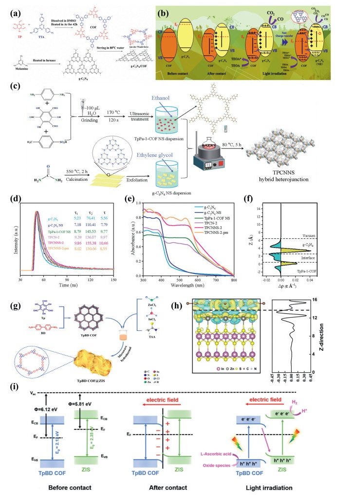
Wang et al. provided a representative example of vdW-mediated assembly in COF-based S-scheme heterojunctions, demonstrating that weak interfacial forces can preserve structural integrity while enabling interfacial electronic coupling and charge separation. Nevertheless, the effectiveness of such vdW interactions is highly constrained by their strong distance dependence. This intrinsic short-range limitation restricts the extent and robustness of interfacial regulation, suggesting that vdW interactions alone may be insufficient for constructing highly efficient and stable heterointerfaces. Accordingly, this motivates the exploration of stronger noncovalent contact modes, particularly interfacial π-π interactions, which offer more effective electronic coupling in COF-based architectures.
π-π interactions are mediated by the spatial overlap of delocalized π orbitals between adjacent aromatic units, and their strength is determined by stacking distance, relative orientation, slip displacement, and degree of planarity [171]. In COF-based S-scheme heterojunctions, π-π coupling provides a more specific orbital-mediated pathway than vdW contact, because it directly governs the extent of interfacial wavefunction overlap and thus the electronic coupling strength [172,173]. A near-parallel and sufficiently close stacking geometry can facilitate ground-state charge redistribution, lower interfacial tunneling barriers, and create anisotropic transport channels along the stacking direction. By contrast, excessive orbital overlap may also promote charge localization, non-radiative recombination, or trap-state formation. Therefore, the photophysical consequences of π-π interactions depend on achieving an optimal balance between coupling strength and recombination suppression rather than maximizing stacking density indiscriminately.
In the case of the TpPa-1-COF/g-C3N4 nanosheet heterojunction reported by Dong et al., exfoliation-induced nanosheet assembly created an extended 2D/2D π-π contact (Fig. 13c), denoted as TPCNNS-x (where x represents the mass ratio of TpPa-1-COF to g-C3N4 NSs), which promoted spontaneous interfacial charge transfer and strengthened the built-in electric field [174]. TRPL measurements revealed a prolonged fluorescence lifetime (τ) for the g-C3N4 NSs, suggesting that the exfoliation process effectively facilitates the separation of photo-generated charge carriers (Fig. 13d). Further characterization demonstrated a redshift in the optical absorption of the TPCNNS heterojunctions, indicating enhanced visible-light harvesting capabilities and an increased generation of photo-excited carriers (Fig. 13e). Concurrently, the optimized interfacial contact and well-defined transport channels significantly promote the migration of photo-generated electrons along the π-π stacking direction (z-direction) (Fig. 13f), thereby optimizing charge separation and transport dynamics in the photocatalytic system. For such 2D/2D π-π coupled systems, only when the two phases are stacked with high spatial matching and effective overlap can the π orbitals form stronger wavefunction coupling, thereby lowering the barrier for interfacial charge transfer and promoting directional electron migration along the stacking axis. In contrast, when the stacking geometry is offset or misaligned, orbital overlap is weakened, coupling is constrained, and carriers are more likely to undergo localized recombination. In this study, the prolonged lifetime revealed by TRPL, the red-shifted absorption, and the enhanced electron migration along the z direction collectively indicate that optimized stacking-induced interfacial coupling facilitates the formation of a stable IEF and suppresses the nonproductive recombination of photogenerated carriers. Thus, this case demonstrates that π-π interactions are not merely simple contact, but an orbital-coupling process precisely regulated by stacking geometry.
Besides, Bao et al. developed a series of TpBD COF@ZIS composites with varying mass ratios through a microwave-assisted hydrothermal strategy [175], in which ZIS nanosheets were in-situ grown on the surface of TpBD COF (Fig. 13g). The synthesis method employed ensures an even distribution of ZIS nanosheets on TpBD COF surfaces, promoting a highly intimate π-π stacking and resulting in substantial orbital overlap at the TpBD COF/ZIS interface. This strong overlap effectively lowers the interfacial charge-transfer barrier and provides a directed electron migration pathway along the stacking axis. DFT analyses reveal stacking-related shifts in charge distribution and interfacial potential, consistent with enhanced wavefunction overlap at the junction (Fig. 13h). Moreover, the enhanced overlap preserves the high redox potentials of the photogenerated carriers while simultaneously facilitating rapid charge separation. In terms of band alignment, the interfacial offsets corroborate an interfacial coupling that is energetically favorable for charge transfer, with reported band offsets ΔECB ≈ 0.21 eV and ΔEVB ≈ 0.44 eV (Fig. 13i). Overall, TpBD COF@ZIS establishes substantial orbital overlap at the heterointerface, thereby reducing the charge-transfer barrier and facilitating directional electron migration along the stacking axis.
Nevertheless, because such interfacial coupling relies primarily on noncovalent π-π interactions, its ability to regulate charge dynamics remains inherently limited. This limitation motivates further consideration of interfacial covalent bonding as a more robust strategy to strengthen interfacial coupling and enhance charge redistribution.
In COF-based S-scheme heterojunctions, interfacial chemical bonds act as highly directional and energetically robust interactions that connect distinct components, such as dual COFs, COF/copolymer, and COF/inorganic hybrid systems. Owing to their intrinsic bond strength and geometric directionality, these linkages are central to interfacial integration, structural stabilization, pore architecture regulation, and the modulation of charge transport and local electronic environments. Specifically, such interfacial bonds include covalent linkages (e.g., C–C, C–N, C–O, C–S, Si–O, and C═O) as well as coordination bonds involving metal centers (e.g., M–N and M–O, where M denotes the metal center) [176]. Covalent interfacial bonding generally affords strong electronic coupling and low-resistance carrier migration, while enabling tunable band-edge positions through the incorporation of electron-donating or electron-withdrawing units. However, overly strong covalent interactions may also generate localized states that act as recombination centers. By contrast, coordination bonds offer directional charge transfer pathways and can improve catalytic selectivity; in particular, the metal valence state and coordination environment critically govern intermediate stabilization and intrinsic catalytic activity [177]. Nevertheless, excessive coordination strength may passivate active sites or promote non-radiative relaxation, thereby compromising charge utilization [178,179].
To mitigate the prevalent issue of charge-carrier recombination in semiconductor photocatalysis, Jiang et al. employed an in-situ growth strategy to anchor TpTt-COF onto the surface of Zr-BTB-NH2 (MOF) [180], thereby achieving covalent coupling through β-ketoenamine linkages and successfully constructing a Zr-BTB-COF S-scheme heterojunction (Fig. 14a). DFT calculations revealed a spontaneous charge transfer of 0.015 e- upon interfacial coupling, indicating that the β-ketoenamine bridge is not merely a geometric linker, but rather induces local electronic redistribution and directional orbital overlap, thereby locking the interfacial coupling orientation at the electronic-structure level (Fig. 14b). Such orbital overlap, dictated by bonding orientation, further translates into enhanced electronic coupling and an optimized charge-transport pathway. As a result, the surface charge density of Zr-BTB-COF-3 increased from 0.29 µC/cm2 for Zr-BTB-NH2 to 0.81 µC/cm2 (Fig. 14c), and the surface photovoltage rose from 3.9 µV to 13.7 µV (Fig. 14d), corresponding to a 9.8-fold enhancement in the built-in electric field (BEF) (Fig. 14e). Ultimately, Zr-BTB-COF-3 achieved CO and anisaldehyde production rates of 71.9 and 44.7 µmol g-1 h-1, respectively, representing 4.1-fold and 3.9-fold increases over Zr-BTB-NH2 (17.8 and 11.5 µmol g-1 h-1) (Figs. 14f and g). These results indicate that a strongly bonded, directionally coupled interface not only improves the separation efficiency of photogenerated charge carriers, but also preserves high redox capability through stable S-scheme charge redistribution. This study demonstrates that the enhanced performance of COF-based S-scheme heterointerfaces arises from the precise regulation of charge behavior by interfacial chemical bonds. In contrast to physical contact or weak interactions, covalent or coordination bonds improve interfacial stability and suppress recombination, while their directionality governs orbital overlap and charge-transport pathways. More importantly, interfacial bonding reshapes the local band structure and built-in electric field, thereby promoting charge separation, migration, and activity retention. Accordingly, later studies have increasingly adopted charge-driven self-assembly and in-situ growth to achieve intimate contact and well-defined interfacial coordination.
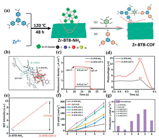
Meanwhile, Tang et al. demonstrated the in-situ growth of CdS nanoparticles on the surface of pre-synthesized PyTdCOF [181]. In this strategy, Cd2+ ions are first anchored onto the PyTdCOF surface via electrostatic adsorption, followed by coordination with nitrogen and sulfur-containing functional groups and subsequent in-situ sulfurization (Fig. 15a), and yielding discretely distributed CdS nanocrystals that form PyTdCOF/CdS S-scheme heterojunctions with tunable stoichiometries. The authors combine in-situ soft X-ray absorption spectroscopy (sXAS) with theory to map the electronic structure evolution and interfacial charge migration; interfacial Cd–N and Cd–S bonds, established via coordination, act as efficient charge-transfer channels that substantially enhance charge separation and photocatalytic performance for H2O2 production and PXG oxidation (Fig. 15b). By integrating in-situ soft X-ray absorption spectroscopy (sXAS) with theoretical calculations, the authors elucidated the electronic structure evolution and charge migration pathways at the heterojunction interface (Fig. 15c). More broadly, electrostatic self-assembly leverages surface-charge interactions to enforce intimate, ordered COF–secondary component contact and often induces coordination or hybridization. Such interfacial interactions modulate work function and Fermi-level alignment, driving band bending and the formation of an IEF. The bonding between inorganic species and COFs can also create hybrid energy levels or localized quantum wells at the interface, collectively dictating S-scheme carrier migration, lifetimes, and recombination kinetics, and thereby shaping the absorption profile, catalytic activity, and selectivity of the composite. On the whole, interface engineering is a key factor in improving the performance of COF-based composite systems. Its role lies not only in enhancing intercomponent synergistic effects, but also in regulating charge transport, suppressing recombination, and improving interfacial reaction behavior through optimized interfacial coupling, thereby leading to enhanced overall performance. Because this mechanism is applicable to a wide range of material combinations, interface engineering has increasingly emerged as a universally applicable strategy in the design of COF composite materials.
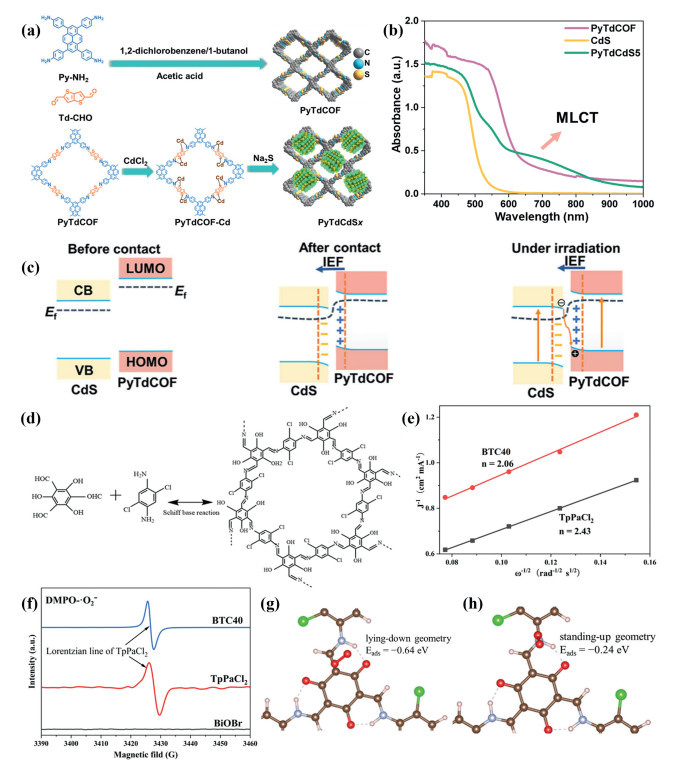
Moreover, Wang and co-workers employed a sonochemical approach to deposit BiOBr nanosheets (NSs) onto a TpPaCl2 COF scaffold (Fig. 15d), successfully fabricating a series of COF-based S-scheme heterojunctions designated as BTCx (where x denotes the weight percentage of BiOBr within the composite) [182]. BTC40 exhibits a high H2O2 production efficiency, which is primarily attributed to the ultrafast charge-transfer dynamics and the resulting S-scheme interfacial kinetics revealed by fs-TAS. The fs-TAS results indicate that photogenerated carriers undergo rapid interfacial separation of low-energy electrons and holes, while the higher-energy electrons and holes remain available to participate in surface redox reactions (Figs. 15e and f). This process is driven by an internal electric field formed at the BiOBr/TpPaCl2 interface due to Fermi-level mismatch. Concurrently, DFT calculations show that O2 adsorbs on the COF surface in a lying-down configuration, enabling a concerted two-electron reduction pathway rather than a stepwise single-electron route (Figs. 15g and h). Collectively, these findings illuminate how ultrafast carrier dynamics and optimized O2 activation synergistically promote H2O2 generation. By leveraging coordination-driven self-assembly, the construction of COF-based S-scheme heterojunctions enables the precise manipulation of charge-carrier dynamics and photocatalytic efficiency via the synergistic integration of energy-band engineering, interfacial electron redistribution, and reactant adsorption modulation. Consequently, this approach provides a versatile design blueprint for the rational interfacial engineering and optimization of high-performance COF-based photocatalytic systems.
In COF-based S-scheme heterojunctions, interfacial engineering can generally be categorized into three types: van der Waals interactions, interfacial π-π interactions, and interfacial chemical bonds (Scheme 2). Overall, the interfacial coupling strength increases progressively from weak to strong across these interaction types: van der Waals interactions typically correspond to low-to-medium coupling, π-π interactions exhibit medium coupling, whereas chemical bonding can achieve medium-to-high coupling. From a performance perspective, van der Waals interfaces are commonly constructed via layer-by-layer self-assembly or in-situ growth, and are therefore advantageous in terms of mild processing conditions, structural tunability, and fabrication convenience, making them attractive for scalable and portable preparation. However, their interfacial stability and charge-coupling capability are relatively limited, with representative reduction rates generally on the order of 102–104 µmol g-1 h-1 for H2, 102–103 µmol g-1 h-1 for H2O2, and 101–102 µmol g-1 h-1 for CO. π-π Interactions rely on coplanar stacking between aromatic backbones and can enhance interfacial charge transfer while preserving good crystallinity and relatively low synthetic complexity. Their typical performance is often superior to that of purely vdW systems, with H2 reduction activities typically ranging from 103 to 105 µmol g-1 h-1. Nevertheless, such interactions remain sensitive to stacking orientation, interlayer slippage, and solvent effects, and thus their stability and directional controllability are still limited. In contrast, interfacial chemical bonds, particularly coordination and covalent bonds, enable the strongest interfacial coupling and markedly promote charge separation, built-in electric field formation, and cooperative band alignment, thereby delivering higher photocatalytic activity. Representative reduction rates can reach 103–105 µmol g-1 h-1 for H2, 103–104 µmol g-1 h-1 for H2O2, and about 102 µmol g-1 h-1 for CO. However, these strategies usually require more elaborate synthetic procedures or harsher reaction conditions, and may to some extent compromise the intrinsic channel structure, crystallinity, or synthetic universality of COFs. Accordingly, different interfacial engineering strategies embody a typical trade-off among performance enhancement, fabrication convenience, and interfacial stability: van der Waals interfaces are more favorable for scalable manufacturing and mild assembly, π-π interfaces provide a balance between structural order and electronic coupling, whereas chemically bonded interfaces offer the highest coupling strength and performance potential at the expense of reduced synthetic simplicity and portability.
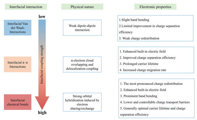
Benefiting from their molecularly designable building blocks, high specific surface areas, ordered pore architectures, and abundant functionalizable sites, COFs provide a versatile platform for interfacial covalent grafting or in-situ growth [183]. These attributes facilitate the formation, intimate interfaces with inorganic semiconductors, thereby establishing efficient electron transport channels and exposing a high density of reactive active sites [184]. Furthermore, by coupling with diverse organic ligands or semiconductors through various bonding modalities, the electronic band structure can be precisely modulated, and internal electric fields can be engineered at the interface. Leveraging these structural and electronic advantages, COF-based S-scheme heterojunctions typically exhibit broadened visible-light absorption, enhanced photogenerated carrier separation efficiency, and the ability to maintain high redox potentials. Consequently, these materials demonstrate exceptional activity, selectivity, and long-term stability in diverse photocatalytic applications, including water splitting for hydrogen evolution, selective H2O2 production, CO2 photoreduction, environmental organic pollutant degradation, and various organic transformations. The following sections will provide a detailed discussion on the photocatalytic applications of COF-based S-scheme heterojunctions.
COF-based S-scheme heterojunction photocatalysts leverage the internal electric field inherent to their heterostructure to effectively facilitate the spatial separation and directional migration of photogenerated charge carriers [185-187]. This mechanism preserves high redox potentials, thereby enabling efficient utilization of solar energy and establishing a novel material design platform for the advancement of green energy and environmental remediation technologies [188-190]. Among these applications, photocatalytic water splitting provides a direct route to harnessing renewable solar energy for hydrogen production [191]. As a clean energy carrier characterized by high energy density and zero carbon emissions, hydrogen can be converted into electrical energy via fuel cells for long-term energy storage, with extensive applications in transportation, chemical synthesis, and distributed energy systems [192,193]. Consequently, COF-based S-scheme photocatalytic hydrogen production not only facilitates the enhancement of solar-to-chemical energy conversion efficiency but also provides fundamental support for the construction of carbon-neutral energy systems. Furthermore, the direct photocatalytic synthesis of hydrogen peroxide from water and oxygen offers significant environmental and industrial value [194-196]. While conventional anthraquinone processes for H2O2 production are plagued by high energy consumption and severe pollution, photocatalytic processes based on COF heterojunction systems enable two-electron oxygen reduction under ambient conditions, adhering to the principles of green chemistry [197-199]. As a crucial green oxidant and disinfectant, the generated H2O2 is widely utilized in organic synthesis, wastewater purification, pulp bleaching, and medical sterilization.
In photocatalytic HER, ascorbic acid (AA) is frequently employed as a sacrificial electron donor, often in conjunction with Pt as a co-catalyst. Upon light-induced generation and subsequent separation of electron-hole pairs, electrons migrate to surface active sites to facilitate proton reduction, whereas holes are consumed by the oxidation of the sacrificial agent. To drive these processes, the CB of the photocatalyst must be positioned at a more negative potential than the hydrogen evolution potential to enable proton reduction to H2. Simultaneously, the VB must be sufficiently positive to drive the oxidation of the sacrificial agent or water. Consequently, conduction band electrons reduce protons (H+) to produce H2, while valence band holes facilitate the oxidation of water to O2:
|
|
|
|
The escalating global energy demand, the depletion of fossil fuels, and the concomitant environmental crises have spurred the development of sustainable and clean energy alternatives. In this context, solar-driven photocatalytic hydrogen production has emerged as a highly promising strategy for both environmental remediation and renewable energy generation. Motivated by this, Ding et al. constructed an organic/inorganic hybrid S-scheme heterojunction by in-situ loading twinned Zn0.5Cd0.5S solid solution (CZS) onto the surface of a fluorenone-based covalent triazine framework (FOCTF) (Fig. 16a), which acts as the oxidation photocatalyst, to enhance interfacial interactions and suppress the photocorrosion of CZS [200]. The FOCTF exhibits a bandgap of approximately 1.91 eV with a VB position of 1.53 eV, while the CZS possesses a bandgap of approximately 2.28 eV and a CB potential of roughly −1.28 eV (Fig. 16b); this favorable band alignment satisfies the thermodynamic requirements for the formation of an S-scheme heterojunction. Characterization results confirm the uniform distribution of FOCTF at the interface and the preservation of the twinned phase structure of CZS, ensuring robust structural stability. Under the S-scheme charge transfer mechanism, photogenerated electrons are directionally transferred from the FOCTF to the CZS, where they recombine with holes at the interface. This process preserves the high redox potential of the system and significantly suppresses charge recombination, thereby enhancing the production of active species such as superoxide radicals (⋅O2-) and hydroxyl radicals (⋅OH). The optimized CZS-2mgFOCTF photocatalyst achieves a hydrogen evolution rate of 247.62 mmol g-1 h-1 (Fig. 16c), which is approximately 3.83 times that of pristine CZS. Furthermore, the catalyst maintains stable activity over six cycles (Fig. 16d), demonstrating the significant potential of organic/inorganic S-scheme heterojunctions in enhancing photocatalytic efficiency and stability. Nevertheless, the current system lacks systematic evidence regarding the nature of interfacial chemical bonding (e.g., covalent, coordination, or van der Waals interactions) and their quantitative impact on band bending and local electric field intensity. Given that interfacial bonding modes directly dictate band-edge modulation, charge transfer kinetics, and recombination dynamics, quantitative studies on the relationship between interfacial bonding and charge carrier dynamics remain of paramount theoretical and engineering significance.
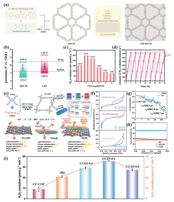
In the context of conventional photocatalytic H2O2 production, the electronic band structure and local electron density of COFs govern the adsorption of O2, the efficiency of electron injection, as well as the formation kinetics and stability of key intermediates (e.g., O2•-). The primary photocatalytic pathways typically involve the two-electron oxygen reduction reaction (2e−-ORR) and the two-electron water oxidation reaction (2e--WOR):
|
|
|
|
However, when the reduction potential of the photogenerated electrons is excessively high, competitive pathways such as the four-electron oxygen reduction reaction (4e--ORR) and the four-electron oxygen evolution reaction (4e- OER) may be triggered:
|
|
|
|
Consequently, COF-based S-scheme heterojunction photocatalysts exhibit dual functionalities in energy conversion and environmental remediation during light-driven H2O2 synthesis. Moving forward, the continuous optimization of their electronic band structures, interfacial coupling, and light absorption efficiencies remains imperative for realizing highly efficient water splitting toward H2 evolution and H2O2 production. Under such development, Xu et al. employed an in-situ growth strategy to construct an S-scheme core–shell heterojunction photocatalyst (CCZS) comprising sp2 carbon-conjugated covalent organic frameworks (CC-COF) and ZnIn2S4 (ZIS) (Fig. 16e) [201]. This core–shell architecture preserves the inherent porosity of CC-COF (BET surface area of 324 m2/g) to provide abundant oxygen adsorption sites (Fig. 16f), while simultaneously leveraging the hydrophilicity of ZIS to facilitate reactant transport. Supported by work function calculations and in-situ XPS analysis, the system achieves significant charge separation and an extended carrier lifetime (τ3 = 5667.6 ps) (Fig. 16g). In-situ DRIFTS measurements identified O2•- and *OOH intermediates, while oxygen adsorption/desorption experiments confirmed an enhanced oxygen adsorption capacity, ultimately contributing to a 2e--ORR selectivity of approximately 70% and an H2O2 production rate of 53.6 µmol g-1 min-1 (Figs. 16h and i). This work demonstrates a synergistic effect between local oxygen enrichment and spatial confinement, effectively coupling the adsorption sites of COFs with the ZIS-mediated hydrophilic transport and charge separation.
Besides, Chen et al. adopted a hydrothermal method to deposit indium sulfide (In2S3) on TpMA COF [202], constructing a TpMA/In2S3 S-scheme heterojunction photocatalyst (Fig. 17a). As a narrow-bandgap n-type semiconductor, In2S3 forms an S-scheme heterojunction with COF, which can promote charge separation and retain strong redox capacity. The optimized 10% TpMA/In2S3 exhibited excellent photocatalytic performance, with a H2O2 yield of 311.07 µmol/L (Fig. 17b). The generated H2O2 could be used for bacterial inactivation in a Fenton system with Fe(Ⅱ) as the catalyst, and under 150 min of visible light irradiation, approximately 6.5 log10 cfu/mL of Escherichia coli cells were completely inactivated (Fig. 17c). The combination of photocatalytic H2O2 production and Fenton sterilization can achieve efficient disinfection without external oxidants, which avoids the cost and safety issues associated with the addition of external H2O2 in the traditional Fenton method and has important application value in environmental disinfection and water pollution control.
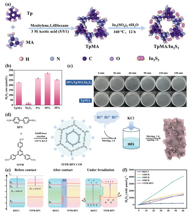
In addition, Zhang et al. successfully constructed a BiOCl/TFPB-BPY S-scheme heterojunction photocatalyst via an in-situ growth strategy (Fig. 17d) [203]. In this architecture, the uniform dispersion of BiOCl nanosheets across the COF framework enables robust interfacial chemical coupling, providing an efficient conduit for interfacial charge transfer. Governed by the S-scheme mechanism, an internal electric field drives the effective migration of photogenerated electrons from the CB of BiOCl to the CB of the COF which serves as the reduction site, while photogenerated holes remain sequestered in the VB of BiOCl (Fig. 17e). This band alignment elegantly optimizes the synergistic redox capability and significantly suppresses the recombination of photogenerated charge carriers. Benefiting from the synergy between the superior charge-transport properties of the COF and the broad-spectrum light absorption of BiOCl, the composite exhibits significantly enhanced photocatalytic performance. Notably, the 20BTB sample achieves an H2O2 production rate of 4088.46 µmol g-1 h-1 (Fig. 17f), representing a 2.8-fold and 19.2-fold improvement over pristine COF and BiOCl, respectively. Coupled with its excellent cyclic stability, these findings highlight the significant potential of S-scheme heterojunctions for efficient photocatalytic hydrogen peroxide production.
The severe challenges posed by global warming have accelerated the development of sustainable strategies for the efficient conversion of CO2 into high-value chemicals [204,205]. Among these, photocatalytic CO2 reduction (CO2RR), which mimics natural photosynthesis, has emerged as a pivotal pathway for carbon cycling and solar-to-chemical energy storage by utilizing semiconductor materials to harvest photons, generate photoexcited electrons, and drive the stepwise PCET reduction of CO2. However, conventional inorganic semiconductors (e.g., TiO2, CdS) are often constrained by wide bandgaps [206], rapid recombination of photogenerated carriers, and poor product selectivity. In contrast, COFs offer a versatile platform for efficient light harvesting, reactant enrichment, and precise catalytic site engineering, owing to their molecularly designable π-conjugated skeletons, high specific surface areas, and ordered crystalline channels. Furthermore, COF-based S-scheme heterojunctions, constructed through interfacial bonding and energy-level coupling, not only broaden the light absorption spectrum and improve charge separation but also allow for the precise modulation of optical bandgaps, surface areas, and pore size distributions via the introduction of organic/inorganic ligands, thereby enhancing CO2 adsorption and activation [207]. Concurrently, band engineering of these heterostructures enables the rational alignment of HOMO/LUMO levels, ensuring that the HOMO edge remains below the potential for water oxidation while the LUMO edge remains above the potential for CO2 reduction. This optimization balances light absorption with thermodynamic driving forces within a bandgap range of approximately 1.7–3.1 eV, ultimately enhancing both the photocatalytic efficiency and product selectivity of CO2RR [208].
|
|
|
|
|
|
|
|
|
|
|
|
|
|
|
|
Consequently, the construction of COF-based S-scheme heterojunctions enables the broadening of the light absorption spectrum and optimized band alignment via interfacial bonding, thereby facilitating the directional migration of photogenerated carriers, suppressing charge recombination, and enhancing both photoelectric conversion efficiency and CO2 reduction selectivity. In this context, He et al. constructed an S-scheme COF/QDs heterojunction photocatalyst by anchoring CsPbBr3 quantum dots (QDs) onto a TPA-COF framework via electrostatic self-assembly (Fig. 18a) [209]. Leveraging the high specific surface area of the COF and the enhanced chemical adsorption facilitated by its basic nitrogen sites, this system establishes an S-scheme charge transfer pathway (Fig. 18b). In this configuration, photoexcited electrons migrate from the LUMO of the COF to the VB of the QDs, where they recombine with holes. This process effectively separates the photogenerated carriers, preserving the highly reductive electrons in the QDs and the highly oxidative holes in the COF, thereby augmenting the overall redox capability and significantly boosting photocatalytic CO2 reduction performance. Notably, the COF/QDs-Ⅱ variant exhibits superior CO2 chemical adsorption, as evidenced by the higher desorption temperature in CO2-TPD profiles and a lower adsorption energy (approx. −0.41 eV) predicted by DFT calculations (Fig. 18c). Under catalyst-free and sacrificial-agent-free conditions, this heterojunction achieves CO and CH4 yields of 41.2 and 13.7 µmol/g (Figs. 18d and e), respectively, with excellent structural and chemical stability maintained over four consecutive cycles. This work underscores the synergistic effect of enhanced CO2 chemical adsorption, S-scheme charge separation, and internal electric field-driven carrier migration in achieving efficient CO2 photoreduction, highlighting the design principles and potential of organic/inorganic heterojunctions in artificial photosynthesis. Nevertheless, the partial blockage of COF pores by QDs, which leads to a reduction in specific surface area and may constrain physical adsorption, necessitates the further development of COF-based S-scheme heterojunctions that simultaneously offer high surface areas and efficient QD loading.
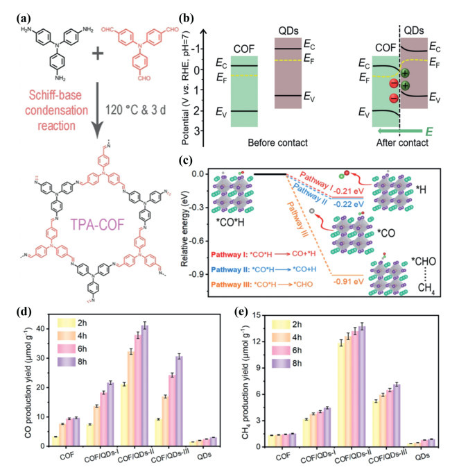
As a quintessential green and sustainable technology, photocatalytic organic synthesis provides a crucial pathway for the preparation of pharmaceutical intermediates and high-value-added chemicals under mild, environmentally benign conditions [210,211]. In particular, the selective oxidation of aromatic alcohols into diverse compounds, including aldehydes, ketones, and amines, which is highly sought after in the fine chemical and pharmaceutical industries. However, these transformations are frequently bottlenecked by high substrate activation barriers, difficult selectivity control, and competitive side reactions. Consequently, there is an urgent need to develop photocatalysts capable of lowering reaction energy barriers and precisely modulating electron–proton transfer pathways [212]. Coupling photocatalytic CO2 reduction with the synthesis of value-added chemicals offers a paradigm-shifting solution [213], which it not only directly stores solar energy within economically viable molecules, realizing the resource utilization of greenhouse gases, but also integrates both oxidation and reduction half-reactions within a single light-driven system. This holistic approach maximizes the electron–proton flux and catalytic site utilization, thereby enhancing atom economy while significantly reducing overall energy consumption and downstream separation costs. Against this backdrop, COF-based S-scheme heterojunctions that endowed with tunable light-harvesting moieties, engineered energy-level cascades, and interfacial linkages, which emerge as a highly viable materials design strategy. By simultaneously optimizing photon absorption efficiency, facilitating the spatial separation of photogenerated carriers, and directing charge migration, these architectures profoundly enhance substrate activation and reaction selectivity. Consequently, they hold immense promise for driving synergistic advancements in the coupled fields of photocatalytic organic synthesis and CO2 valorization.
Conventional photocatalytic CO2 reduction typically relies on sacrificial agents, which inherently limits the energy efficiency and economic viability of the process. In this context, coupling CO2 reduction with the selective oxidation of biomass-derived alcohols emerges as a compelling strategy to significantly enhance photogenerated carrier utilization and atom economy. To this end, Wang et al. fabricated metal-doped M-ZIS/TpPa-1 S-scheme heterojunctions (M = Ni or Mo) via a one-pot synthetic strategy, where ZnIn2S4 (ZIS), TpPa-1 COF [214], and transition metals (Ni or Mo) were integrated synchronously (Fig. 19a). The constructed S-scheme heterojunction facilitates the separation of photogenerated charge carriers while retaining robust redox capability. Transition metal doping can regulate the electronic structure of ZIS to optimize H adsorption/desorption behavior, and simultaneously elevate the Fermi level to enhance the IEF of the heterojunction (Fig. 19b). Compared with Ni-ZIS/TpPa-1 and ZIS/TpPa-1 composites, the modified Mo-ZIS/TpPa-1 exhibits enhanced performance in visible-light-driven bifunctional photocatalytic hydrogen evolution coupled with benzylamine oxidation. Specifically, Mo0.01-ZIS/TpPa-1 achieves a hydrogen evolution rate of 1648 µmol g-1 h-1 and an N-benzylidenebenzylamine formation rate of 1812 µmol g-1 h-1 under visible light irradiation, which are 1.7 times and 1.9 times those of ZIS/TpPa-1, respectively, along with excellent cyclic stability (Figs. 19c and d). The synergistic effects of S-scheme charge transfer, metal doping-induced optimization of H adsorption/desorption, and IEF enhancement significantly promote the separation and transfer of photogenerated carriers, thereby boosting the overall photocatalytic activity.
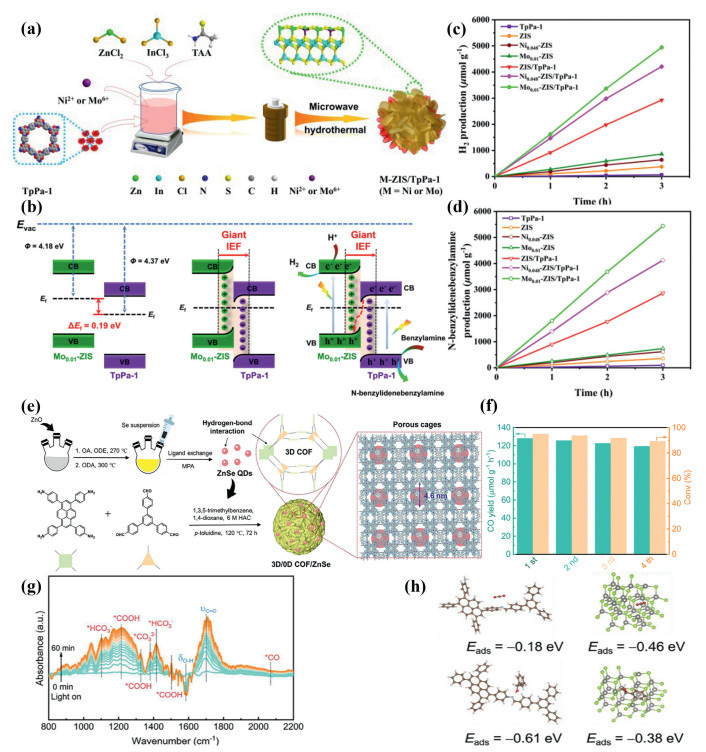
Moreover, Cheng et al. designed and synthesized a porous, cage-like three-dimensional covalent organic framework (3D COF) (Fig. 19e) [215]. The large-pore channels of this framework not only facilitate the encapsulation of quantum dots (QDs) and the diffusion of reactants and thereby mitigating QD aggregation and mass-transfer limitations, but also serve as a confinement platform for constructing a 3D COF/ZnSe QD S-scheme heterojunction via coordination bonding. This heterojunction architecture leverages an S-scheme charge-transfer mechanism to enhance CO2 adsorption (2.5 mmol/g) and boost overall catalytic activity. Notably, the COF/ZnSe-1 variant exhibits optimal performance, achieving a CO evolution rate of 128.3 µmol g-1 h-1 and a 1-phenylethanol conversion of 95.1% (Fig. 19f), with excellent catalytic stability maintained over four consecutive cycles. Systematic characterization, corroborated by in-situ DRIFTS, reveals that photogenerated electrons migrate directionally from the LUMO of the COF to the VB of the ZnSe, preserving strong oxidation/reduction potentials while facilitating the detection of the *COOH intermediate, thus confirming the CO2 reduction pathway (Fig. 19g). Furthermore, DFT calculations disclose a spatial segregation of reaction centers, wherein the COF preferentially adsorbs 1-phenylethanol, while the ZnSe preferentially activates CO2 (Fig. 19h). While this S-scheme coupling strategy establishes a versatile design paradigm for bifunctional photocatalysis, particularly for the concurrent CO2 photoreduction and selective oxidation of biomass-derived alcohols, several challenges remain. Although this S-scheme coupling strategy provides a universal design approach for efficiently realizing the bifunctional photocatalysis of CO2 photoreduction and selective oxidation of biomass alcohols, the COF architectures are susceptible to structural degradation under alkaline conditions, and excessively high QD loading will induce interfacial agglomeration and thus compromise photon utilization efficiency. Therefore, it is imperative to develop alkali-resistant COF-based S-scheme heterojunctions that are applicable to a broad spectrum of coupled reactions, as well as to optimize the QD loading and dispersion strategies, thereby enhancing the long-term stability and photocatalytic efficiency of the hybrid systems.
Photocatalytic organic synthesis and the valorization of carbon dioxide represent pivotal directions in sustainable chemical manufacturing. However, these processes are frequently constrained by high activation energy barriers, limited carrier utilization, and the reliance on sacrificial agents. To overcome these challenges, COF-based S-scheme heterojunctions have emerged as a sophisticated materials design strategy, leveraging tunable light-harvesting moieties, engineered energy-level cascades, and interfacial linkages to precisely modulate electron–proton transfer pathways. By integrating photocatalytic CO2 reduction with the selective oxidation of biomass-derived alcohols that as exemplified by the high-performance M-ZIS/TpPa-1 and 3D COF/ZnSe QD systems, these architectures achieve a holistic maximization of electron flux and catalytic site utilization, which effectively abolishing the need for sacrificial reagents while enhancing atom economy. Notably, the spatial segregation of redox centers and the synergy between structural confinement and directional charge migration facilitate superior catalytic activity and selectivity. Despite these breakthroughs, the long-term viability of these hybrid systems remains challenged by the structural vulnerability of COFs in extreme pH environments and the interfacial agglomeration of co-catalysts. Consequently, future research must prioritize the rational design of alkali-stable frameworks and the optimization of interfacial dispersion strategies, thereby establishing a robust technical foundation for the scalable and efficient coupling of solar-driven organic synthesis with greenhouse gas resource utilization.
Organic pollutants, such as Rhodamine B and triclosan (TCS), are ubiquitously utilized in personal care products, medical formulations, and textiles [216]. Their widespread application leads to significant discharge into aquatic environments and sediments via domestic sewage, industrial effluents, and solid waste streams. These compounds exhibit high environmental persistence and bioaccumulation potential, resulting in chronic exposure risks to both ecosystems and human populations [217]. Triclosan, in particular, warrants serious concern due to its multifaceted ecological and human health risks, including endocrine disruption, acute and chronic aquatic toxicity, the selective promotion of antimicrobial resistance genes, and the potential mutagenicity or carcinogenicity of its partial oxidation products [218,219]. Current remediation strategies present inherent trade-offs: While adsorption offers rapid removal, it primarily facilitates phase transfer rather than degradation, necessitating secondary disposal of spent adsorbents. Advanced oxidation processes can effectively cleave pollutant structures but are often energy-intensive and prone to generating toxic byproducts [220]. Conversely, biological treatment methods are cost-effective but frequently suffer from inhibition by pollutant toxicity and limited degradation kinetics [221,222]. Consequently, there is an urgent need to develop sustainable technologies that integrate high removal efficiency, low energy consumption, and minimal secondary pollution risks. COF-based S-scheme heterojunctions represent a promising strategy in this regard. Their highly tunable pore structures and functional sites facilitate the enrichment and near-field activation of target pollutants, while their ordered conjugated frameworks allow for precise modulation of optoelectronic properties to enhance photogenerated carrier generation. Furthermore, the staggered band alignment promotes the spatial, directional separation of electron-hole pairs, effectively suppressing recombination. Surface functionalization can further improve selective adsorption and mitigate the formation of persistent intermediates, thereby promoting deep oxidation and mineralization into low-toxicity small molecules.
In this context, Zhao et al. synthesized a 3D flower-like Schiff base COF (TD-COF) and subsequently employed an in-situ self-assembly strategy to hybridize it with g-C3N4, forming an S-scheme heterojunction characterized by intimate interfacial contact facilitated by π-π interactions (Fig. 20a) [223]. Systematic characterization reveals a staggered band alignment between TD-COF (Eg = 2.59 eV) and g-C3N4 (Eg = 2.75 eV) (Fig. 20b). Upon photoexcitation, electrons migrate directionally from the TD-COF to the g-C3N4, thereby significantly enhancing charge-carrier separation efficiency. The optimal composite, 10% COF/g-C3N4, demonstrates synergistic photocatalytic performance under an O2 atmosphere, achieving a H2O2 production rate of 2307 µmol g-1 h-1 and the complete degradation of RhB within 45 min (Figs. 20c and d). Active species trapping experiments further indicate that holes (h+) and superoxide radicals (·O2-) are the dominant species for RhB degradation, whereas electrons (e-) and ·O2- primarily drive H2O2 generation (Fig. 20e). These findings demonstrate that the S-scheme heterojunction not only extends charge-carrier lifetime and preserves strong redox potentials through spatial directional separation, but also achieves the synchronous utilization of photogenerated electrons and holes by effectively coupling H2O2 production with organic pollutant degradation. By eliminating the reliance on sacrificial agents, this study underscores the significant potential of COF-based S-scheme heterojunctions for efficient H2O2 synthesis and synergistic pollutant remediation.
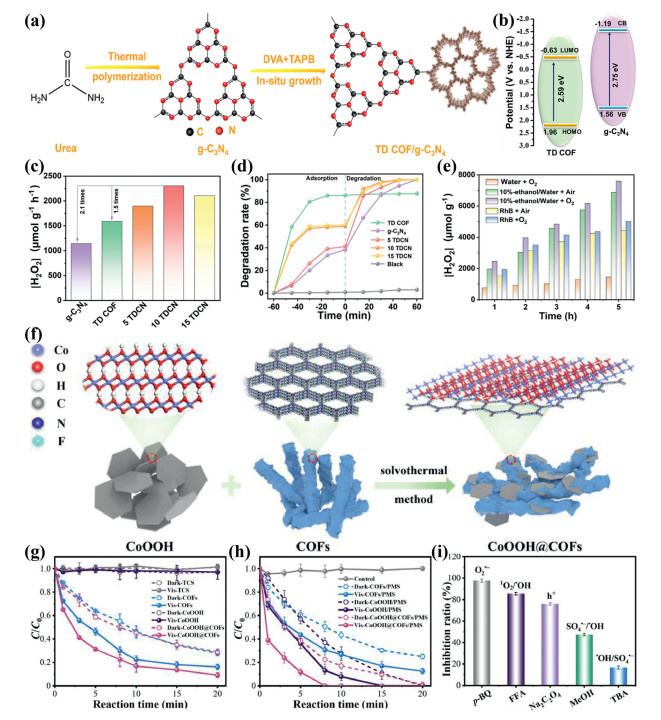
Furthermore, COF-based S-scheme heterojunctions enable the synergistic photodegradation of triclosan. Zhang et al. fabricated a CoOOH@COFs S-scheme heterojunction utilizing an in-situ solvothermal growth strategy, and demonstrates excellent visible-light-harvesting capabilities (Fig. 20f) [224]. By integrating visible-light-driven photocatalysis with peroxymonosulfate (PMS) activation, the system achieves synergistic degradation of triclosan (TCS), reaching 100% removal within 8 min with a reaction rate constant of 0.456 min-1 (Figs. 20g and h), significantly outperforming pristine CoOOH, COFs, and dark control systems. Experimental results, corroborated by DFT calculations, indicate that the S-scheme heterojunction accelerates PMS activation by facilitating photogenerated carrier separation and interfacial electron transfer. This process generates a suite of reactive oxygen species (ROS), including O2·-, ·OH, SO4·-, and 1O2. Notably, the capture of electrons by PMS suppresses charge recombination, establishing O2·- as the dominant intermediate (contributing >90% to the degradation) (Fig. 20i). The catalyst exhibits remarkable stability and reusability, highlighting the potential of the synergistic effect between photogenerated electrons and PMS activation for the efficient degradation of refractory organic pollutants. Despite notable progress in the photocatalytic performance of COF/g-C3N4 heterojunctions, systematic insights into the interfacial bonding mechanisms governing charge transfer across organic/inorganic interfaces remain elusive. Additionally, the field currently lacks comprehensive assessments regarding the structural durability and field-scale applicability of these materials under the challenging conditions inherent to complex environmental water matrices. Consequently, it is imperative to further optimize the interface engineering of COF-based S-scheme heterojunctions to improve interfacial coupling strength and ordered directional charge transfer. Future research should prioritize enhancing carrier separation and catalytic activity, while expanding the scope to coupled reaction systems, such as simultaneous pollutant degradation and H2O2 production, hydrogen evolution, or CO2 reduction, to rigorously evaluate their engineering potential and feasibility for large-scale wastewater treatment.
Addressing the inherent trade-offs between removal efficiency and secondary pollution characteristic of conventional wastewater treatment technologies, COF-based S-scheme heterojunctions offer a promising solution owing to their highly tunable pore architectures, precise band alignment, and superior charge-separation kinetics. Analyses of representative systems, such as TD-COF/g-C3N4 and CoOOH@COFs, demonstrate that S-scheme heterojunctions not only achieve spatially directional charge separation while preserving robust redox potentials through interfacial engineering, but also fundamentally enhance the degradation and mineralization of refractory pollutants via synergistic coupling with PMS activation and the production of value-added chemicals like H2O2. Despite these notable advancements, transitioning from laboratory-scale research to practical engineering applications necessitates a deeper elucidation of the fundamental coupling mechanisms across organic/inorganic interfaces. Furthermore, future efforts must prioritize enhancing the structural durability and multifunctional integration of these materials within complex aqueous matrices, thereby providing a solid theoretical foundation and technical framework for the development of highly efficient, sustainable, and eco-friendly industrial wastewater remediation technologies.
Across the reported COF-based S-scheme photocatalytic systems, the observed performance differences are mainly governed by three coupled factors: Interfacial coupling quality, intrinsic COF structural properties, and reactant transport/adsorption capability. In particular, systems with well-defined heterointerfaces, such as core-shell architectures or in-situ grown hybrids, generally exhibit more efficient charge separation, stronger band bending, and longer carrier lifetimes than physically mixed counterparts. For example, the CCZS core-shell photocatalyst benefits from preserved COF porosity, enhanced oxygen adsorption, and hydrophilic transport pathways, which together promote 2e--ORR selectivity and H2O2 formation. By contrast, insufficiently characterized interfacial bonding or excessive QD loading can trigger agglomeration, weaken photon utilization, and reduce catalytic efficiency. In alkaline or harsh reaction environments, structural instability of the COF framework further becomes a dominant factor limiting long-term performance.
These comparisons suggest several practical conclusions. First, interface engineering should be prioritized over simple component combination, because the nature of chemical bonding and the extent of band alignment largely determine charge-transfer kinetics and recombination losses. Second, maintaining porosity, crystallinity, and accessible active sites is essential, especially when COFs serve as adsorption or confinement platforms. Third, the material loading should be optimized carefully, since excessive loading may induce interfacial aggregation and hinder both light propagation and mass transport. Therefore, future work should focus on establishing quantitative correlations among bonding modes, local electric fields, and carrier dynamics, as well as on the development of pH-stable, dispersion-controlled, and in-situ molecularly characterized COF-based S-scheme heterojunctions to support scalable photocatalytic applications.
In recent years, although inorganic photocatalysts such as TiO2, ZnO, WO3, and Fe2O3 have achieved substantial progress, organic photocatalytic materials have also emerged as promising candidates for solar-to-chemical energy conversion. Among them, COFs stand out owing to their programmable backbones, tunable band structures, periodic pore channels, and versatile interfacial coupling modes, rendering them particularly attractive for constructing S-scheme heterojunctions. Their ordered layered architectures, extended π-conjugation, low defect density, high crystallinity, and excellent chemical stability collectively facilitate precise band alignment, the formation of a robust built-in electric field, and efficient charge separation. Meanwhile, strengthened interfacial electronic coupling and improved reactant adsorption and mass transport further endow COF-based systems with considerable promise in photocatalytic activity, selectivity, and overall efficiency.
Despite these encouraging advances, COF-based S-scheme heterojunctions remain at an early stage of development, and several critical challenges must still be addressed. First, the rational construction of well-defined interfaces remains nontrivial, as van der Waals interactions, π-π stacking, and covalent bonding can profoundly influence band alignment, charge-transport kinetics, and the accessibility of active sites. Although covalent coupling can enhance interfacial electronic communication and structural robustness, it often requires harsh synthetic conditions that may compromise framework integrity or induce interfacial heterogeneity. Accordingly, future efforts should focus on mild, directional, and reproducible interfacial engineering strategies that enable atomic-level control over bonding motifs and coordination environments while preserving long-range structural order. Second, there is a pressing need for in-situ characterization techniques capable of resolving dynamic interfacial processes under realistic reaction conditions. Conventional ex situ methods typically provide static or spatially averaged information, making it difficult to directly capture localized charge accumulation, band bending, intermediate evolution, and interfacial reconstruction. The integration of multimodal operando characterization with theoretical modeling will therefore be essential for establishing quantitative structure–carrier–catalysis relationships.
Going forward, data-driven strategies are expected to accelerate the discovery and optimization of high-performance COF-based heterojunctions. Machine learning, in particular, can facilitate the screening of donor-acceptor COF pairings, interfacial modifiers, and synthetic routes, while the integration of structural descriptors, electronic parameters, and catalytic performance data may help establish generalizable design principles and reduce reliance on trial-and-error experimentation. In parallel, the field would benefit from standardized protocols for stability evaluation, deactivation analysis, and performance benchmarking, thereby improving comparability across different systems. Overall, COF-based S-scheme heterojunctions represent a highly promising platform for photocatalytic solar energy conversion and environmental remediation; however, their practical deployment will depend on continued advances in controllable synthesis, operando characterization, data-guided design, standardized evaluation, and scalable fabrication.
Yingyin Mo: Writing – original draft, Investigation, Formal analysis, Data curation, Conceptualization. Xinghua Wen: Writing – original draft, Formal analysis, Data curation. Ziyang Ke: Writing – original draft, Formal analysis. Can Huang: Writing – original draft, Formal analysis, Data curation. Rongchen Shen: Writing – review & editing, Formal analysis. Song Wang: Writing – review & editing, Formal analysis. Xiang Li: Writing – review & editing, Formal analysis. Jianmin Luo: Writing – review & editing, Formal analysis. Xin Li: Writing – review & editing, Writing – original draft, Project administration, Funding acquisition, Formal analysis, Data curation, Conceptualization.
The authors declare that they have no known competing financial interests or personal relationships that could have appeared to influence the work reported in this paper.
This research is supported by National Natural Science Foundation of China (Nos. 22378148, 21975084, 22308113) and Natural Science Foundation of Guangdong Province (No. 2024A1515012433).
X. Wang, K. Maeda, A. Thomas, et al., Nat. Mater. 8 (2009) 76–80. doi: 10.1038/nmat2317
Y. Han, Z.T. Li, J. Tian, Artif. Photosynth. 1 (2025) 293–318. doi: 10.1021/aps.5c00006
W. Meng, Y. Zhou, Y. Zhou, Chin. Chem. Lett. 36 (2025) 109961. doi: 10.1016/j.cclet.2024.109961
F. Yi, Y. Liu, Y. Chen, et al., Chin. Chem. Lett. 36 (2025) 110544. doi: 10.1016/j.cclet.2024.110544
F. Mohamadpour, A.M. Amani, RSC Adv. 14 (2024) 20609–20645. doi: 10.1039/d4ra03259d
F.E. Osterloh, Chem. Soc. Rev. 42 (2013) 2294–2320. doi: 10.1039/C2CS35266D
T.Y. Shang, L.H. Lu, Z. Cao, et al., Chem. Commun. 55 (2019) 5408–5419. doi: 10.1039/c9cc01047e
P. Usubharatana, D. McMartin, A. Veawab, P. Tontiwachwuthikul, Ind. Eng. Chem. Res. 45 (2006) 2558–2568. doi: 10.1021/ie0505763
J. Xiao, X. Liu, L. Pan, et al., ACS Catal. 10 (2020) 12256–12283. doi: 10.1021/acscatal.0c03480
S. Yoshino, T. Takayama, Y. Yamaguchi, A. Iwase, A. Kudo, Acc. Chem. Res. 55 (2022) 966–977. doi: 10.1021/acs.accounts.1c00676
X.L. Zhong, T. Chervy, L. Zhang, et al., Angew. Chem. Int. Ed. 56 (2017) 9034–9038. doi: 10.1002/anie.201703539
X. Li, Y. Wan, Y. Xie, et al., Adv. Funct. Mater. 36 (2025) e23047.
J.H. Carey, J. Lawrence, H.M. Tosine, Bull. Environ. Contam. Toxicol. 16 (1976) 697–701. doi: 10.1007/BF01685575
A. Fujishima, K. Honda, Nature 238 (1972) 37–38. doi: 10.1038/238037a0
Z. Ashrafi-Peyman, A. Jafargholi, A.Z. Moshfegh, J. Phys. Chem. C 129 (2025) 19493–19504. doi: 10.1021/acs.jpcc.5c03594
X. Chen, S.S. Mao, Chem. Rev. 107 (2007) 2891–2959. doi: 10.1021/cr0500535
Z. Gu, J. Yang, H. Liu, et al., J. Environ. Chem. Eng. 13 (2025) 115802. doi: 10.1016/j.jece.2025.115802
A. Kudo, Y. Miseki, Chem. Soc. Rev. 38 (2009) 253–278. doi: 10.1039/B800489G
X. Li, R. Shen, S. Ma, X. Chen, J. Xie, Appl. Surf. Sci. 430 (2018) 53–107. doi: 10.1117/12.2501104
K. Maeda, K. Domen, J. Phys. Chem. Lett. 1 (2010) 2655–2661. doi: 10.1021/jz1007966
M. Uribe-López, M. Hidalgo-López, R. López-González, et al., J. Photochem. Photobiol. A: Chem. 404 (2021) 112866. doi: 10.1016/j.jphotochem.2020.112866
P. You, D. Chen, X. Liu, et al., Nat. Mater. 23 (2024) 1100–1106. doi: 10.1038/s41563-024-01900-5
J. Zhang, X. Sun, T. Wang, et al., Opt. Mater. 136 (2023) 113498. doi: 10.1016/j.optmat.2023.113498
X. Li, T. Han, Y. Zhou, et al., Appl. Catal. B: Environ. 350 (2024) 123913. doi: 10.1016/j.apcatb.2024.123913
Z. Huang, C. Guo, Q. Zheng, et al., Chin. Chem. Lett. 35 (2024) 109580. doi: 10.1016/j.cclet.2024.109580
M. Chen, L. Zhao, X. Shi, et al., Chin. Chem. Lett. 35 (2024) 109336. doi: 10.1016/j.cclet.2023.109336
Y. Ma, C. Wu, Y. Zhao, et al., J. Mater. Sci. Technol. 255 (2026) 287–307. doi: 10.1016/j.jmst.2025.08.023
T. Gao, D. Shi, X. Liu, X. Wu, G. Wang, J. Mater. Sci. Technol. 251 (2026) 241–251. doi: 10.1016/j.jmst.2025.07.006
F. Liu, X. Li, B. Sun, et al., J. Mater. Sci. Technol. 250 (2026) 233–242. doi: 10.1007/978-981-95-0982-9_19
R. Liu, X. Zhang, X. Han, et al., Carbon Lett. 34 (2024) 75–83. doi: 10.1007/s42823-023-00661-6
X. Chen, S. Shen, L. Guo, S.S. Mao, Chem. Rev. 110 (2010) 6503–6570. doi: 10.1021/cr1001645
J.M. Doña-Rodríguez, E. Pulido Melián, Nanomaterials 11 (2021) 688. doi: 10.3390/nano11030688
H. Wang, X. Li, X. Zhao, et al., Chin. J. Catal. 43 (2022) 178–214. doi: 10.1016/S1872-2067(21)63910-4
R. Sun, B. Tan, Chem. Eur. J. 29 (2023) e202203077. doi: 10.1002/chem.202203077
P.J. Waller, F. Gándara, O.M. Yaghi, Acc. Chem. Res. 48 (2015) 3053–3063. doi: 10.1021/acs.accounts.5b00369
A.P. Côté, A.I. Benin, N.W. Ockwig, et al., Science 310 (2005) 1166–1170. doi: 10.1126/science.1120411
B. Mishra, A. Alam, A. Chakraborty, et al., Adv. Mater. 37 (2025) 2413118. doi: 10.1002/adma.202413118
P. Kuhn, M. Antonietti, A. Thomas, Angew. Chem. Int. Ed. 47 (2008) 3450–3453. doi: 10.1002/anie.200705710
L. Stegbauer, K. Schwinghammer, B.V. Lotsch, Chem. Sci. 5 (2014) 2789–2793. doi: 10.1039/C4SC00016A
W. Hao, R. Chen, Y. Zhang, Y. Wang, Y. Zhao, ACS Omega 6 (2021) 23782–23787. doi: 10.1021/acsomega.1c02592
Z. Qian, Z.J. Wang, K.A. Zhang, Chem. Mater. 33 (2021) 1909–1926. doi: 10.1021/acs.chemmater.0c04348
L. Chen, S. Qin, J. Hang, et al., Catal. Sci. Technol. 15 (2025) 135–144. doi: 10.1039/d4cy01096e
Y. Chen, D. Jiang, Acc. Chem. Res. 57 (2024) 3182–3193. doi: 10.1021/acs.accounts.4c00517
J. Li, Z. Zhang, J. Jia, X. Liu, Chem. Res. Chin. Univ. 38 (2022) 275–289. doi: 10.1007/s40242-022-1434-1
Z.R. Rao, X.Q. Ran, Z.Q. Li, et al., Nat. Commun. 17 (2026) 3896. doi: 10.1038/s41467-026-70311-8
Y. Wang, H. Wang, Y. Liu, et al., Chin. Chem. Lett. 36 (2025) 110189. doi: 10.1016/j.cclet.2024.110189
L. Ou, Z. Xue, B. Li, et al., Chin. Chem. Lett. 36 (2025) 110294. doi: 10.1016/j.cclet.2024.110294
A. Shu, C. Qin, M. Li, et al., Energy Environ. Sci. 17 (2024) 4907–4928. doi: 10.1039/d4ee01379d
T. Hisatomi, T. Yamada, H. Nishiyama, T. Takata, K. Domen, Nat. Rev. Mater. 10 (2025) 769–782. doi: 10.1038/s41578-025-00823-0
M.K. Hussain, R. Liu, M. Tanveer, N. Khalid, Z. Yin, Chem. Synth. 5 (2025) 40.
Z. Zhang, Y. Qian, H.L. Jiang, Chem 12 (2026) 102778. doi: 10.1016/j.chempr.2025.102778
Y. Lu, D. Zhang, L. Fang, et al., Appl. Catal. B: Environ. 387 (2026) 126501. doi: 10.1016/j.apcatb.2026.126501
P. Dong, Y. Zhang, L. Zhang, et al., ACS Catal. 15 (2025) 18138–18154. doi: 10.1021/acscatal.5c05148
X. Zhu, L. Chen, K. Xiong, et al., J. Am. Chem. Soc. 148 (2026) 15099–15113. doi: 10.1021/jacs.6c00731
H. Li, J. Fan, M. Ran, et al., Angew. Chem. Int. Ed. 64 (2025) e202500937. doi: 10.1002/anie.202500937
Y. Yang, K. Zeng, Y. Feng, et al., Angew. Chem. Int. Ed. 65 (2026) e25864. doi: 10.1002/anie.202525864
Y. Zhang, X. Wu, P. Dong, et al., Adv. Funct. Mater. 36 (2026) e75145. doi: 10.1002/adfm.75145
H. Zhang, D. Ba, C.Y. Zou, et al., Angew. Chem. Int. Ed. 65 (2026) e19829. doi: 10.1002/anie.202519829
Y. Zhang, Z. Liang, K. Wang, et al., J. Am. Chem. Soc. 148 (2026) 16107–16118. doi: 10.1021/jacs.6c00641
T. Yang, F. Kong, M. Li, et al., Angew. Chem. Int. Ed. 65 (2026) e202513616. doi: 10.1002/anie.202513616
F. Liu, H. Li, Z. Gao, et al., Nat. Water 4 (2026) 334–347. doi: 10.1038/s44221-026-00590-4
A. Meng, X. Wu, Z. Lu, et al., Angew. Chem. Int. Ed. 65 (2026) e25871. doi: 10.1002/anie.202525871
X. Xiong, L. Gui, L. Yang, et al., J. Mater. Chem. A 13 (2025) 16839–16849. doi: 10.1039/d5ta00933b
Y. Teng, X.-M. Zhang, R.-L. Zhu, et al., Angew. Chem. Int. Ed. 64 (2025) e202516296. doi: 10.1002/anie.202516296
M. Dai, H. Yu, W. Chen, et al., Chem. Eng. J. 470 (2023) 144240. doi: 10.1016/j.cej.2023.144240
Z. Wang, Z. Lin, S. Shen, W. Zhong, S. Cao, Chin. J. Catal. 42 (2021) 710–730. doi: 10.1016/S1872-2067(20)63698-1
H. Guo, S. Wang, X. Chen, et al., Nat. Synth. 4 (2025) 1610–1620. doi: 10.1038/s44160-025-00880-x
C. Gao, Y. Sun, S. Yu, et al., Chem. Eng. J. 500 (2024) 156944. doi: 10.1016/j.cej.2024.156944
S. Wang, W. Hao, Z. Liu, et al., ACS Nano 20 (2026) 137–162. doi: 10.1021/acsnano.5c18705
Y. Wang, K. Du, R. Xu, et al., Curr. Opin. Green Sustain. Chem. 41 (2023) 100824. doi: 10.1016/j.cogsc.2023.100824
Y. Yuan, J. Pan, W. Yin, et al., Chin. Chem. Lett. 35 (2024) 108724. doi: 10.1016/j.cclet.2023.108724
X. Chen, Y. Wu, Y. Tang, et al., Chin. Chem. Lett. 35 (2024) 109245. doi: 10.1016/j.cclet.2023.109245
S. Cong, S. Zhou, J. You, L. Wang, X. Wang, Small 21 (2025) e05905. doi: 10.1002/smll.202505905
F. Yang, X. Wang, Y. Lu, et al., Adv. Funct. Mater. 36 (2026) e74808. doi: 10.1002/adfm.74808
H. Ren, F. Qi, A. Labidi, et al., Appl. Catal. B: Environ. 330 (2023) 122587. doi: 10.1016/j.apcatb.2023.122587
H. Ren, S. Wang, A. Labidi, et al., Sep. Purif. Technol. 362 (2025) 131717. doi: 10.1016/j.seppur.2025.131717
J. Ye, B. Liu, X. Wang, et al., Appl. Surf. Sci. 712 (2025) 164230. doi: 10.1016/j.apsusc.2025.164230
B. Zhu, J. Sun, Y. Zhao, L. Zhang, J. Yu, Adv. Mater. 36 (2024) 2310600. doi: 10.1002/adma.202310600
X. Li, Y. Wan, F. Deng, et al., Chin. Chem. Lett. 36 (2025) 111418. doi: 10.1016/j.cclet.2025.111418
L. Cheng, X. Guo, J. Luo, et al., J. Photochem. Photobiol. A: Chem. 469 (2025) 116545. doi: 10.1016/j.jphotochem.2025.116545
H. Han, X. Wang, Y. Qiao, et al., J. Alloys Compd. 933 (2023) 167819. doi: 10.1016/j.jallcom.2022.167819
W. Li, J. Luo, J. Liu, et al., Surf. Interfaces 46 (2024) 104144. doi: 10.1016/j.surfin.2024.104144
J. Luo, H. Han, J. Wu, et al., Appl. Surf. Sci. 604 (2022) 154512. doi: 10.1016/j.apsusc.2022.154512
L. Zhang, J. Zhang, J. Yu, H. García, Nat. Rev. Chem. 9 (2025) 328–342. doi: 10.1038/s41570-025-00698-3
L. Miao, S. Wang, H. Song, et al., Appl. Catal. B: Environ. 388 (2026) 126533. doi: 10.1016/j.apcatb.2026.126533
L. Zhang, J. Zhang, H. Yu, J. Yu, Adv. Mater. 34 (2022) 2107668. doi: 10.1002/adma.202107668
C. Wang, Y. Zhao, C. Cheng, et al., Coord. Chem. Rev. 521 (2024) 216177. doi: 10.1016/j.ccr.2024.216177
J. Yan, L. Wei, Acta Phys. Chim. Sin. 40 (2024) 2312024. doi: 10.3866/pku.whxb202312024
B.B. Luan, X. Chu, Y. Wang, et al., Adv. Mater. 36 (2024) 2412653. doi: 10.1002/adma.202412653
X. Wu, M. Sayed, G. Wang, W. Yu, B. Zhu, Adv. Mater. 38 (2026) e11322. doi: 10.1002/adma.202511322
T. Zhou, Y. Ma, H. Feng, et al., Adv. Funct. Mater. 34 (2024) 2409396. doi: 10.1002/adfm.202409396
L. Yang, Z. Wu, H. Hou, W. Chen, Y. Li, J. Mater. Sci. Technol. 275 (2026) 271–285. doi: 10.3390/cancers18020271
P. Hao, Z. Chen, Y. Yan, W. Shi, F. Guo, Sep. Purif. Technol. 330 (2024) 125302. doi: 10.1016/j.seppur.2023.125302
Y. Xi, W. Chen, W. Dong, et al., ACS Appl. Mater. Interfaces 13 (2021) 39491–39500. doi: 10.1021/acsami.1c11233
C.H. Bao, L. Li, X.F. Wang, et al., Nano Lett. 25 (2025) 4115–4136. doi: 10.1021/acs.nanolett.4c06680
J. Shao, H. Wang, X. Tao, G. Zhu, Chem. Sci. 16 (2025) 13267–13275. doi: 10.1039/d5sc00394f
Y. Bian, Z. Wang, M. Du, et al., Adv. Funct. Mater. 36 (2026) e19493. doi: 10.1002/adfm.202519493
X.Q. Qiao, H. Guo, P. Du, et al., J. Energy Chem. 113 (2026) 1–11.
L. Yuan, C. Zhang, Y. Zou, et al., Adv. Funct. Mater. 33 (2023) 2214627. doi: 10.1002/adfm.202214627
C. Cui, X. Xu, X. Zhao, et al., Nano Energy 126 (2024) 109632. doi: 10.1016/j.nanoen.2024.109632
B. Feng, B. Qi, S. Wang, et al., Energy Environ. Mater. 9 (2026) e70153. doi: 10.1002/eem2.70153
X. Ma, S. Li, Y. Gao, et al., Adv. Funct. Mater. 34 (2024) 2409913. doi: 10.1002/adfm.202409913
Y. Zhao, Y. Zhang, H. Tan, C. Ai, J. Zhang, J. Materiomics 11 (2025) 100970. doi: 10.1016/j.jmat.2024.100970
Y. Zhang, J. Pan, X. Ni, et al., Chin. J. Catal. 74 (2025) 250–263. doi: 10.1016/S1872-2067(25)64664-X
N.N. Zhang, Y. Sun, X.R. Liu, et al., Adv. Funct. Mater. 36 (2025) e23743.
H. Hu, X. Zhang, K. Zhang, et al., Adv. Energy Mater. 14 (2024) 2303638. doi: 10.1002/aenm.202303638
A. Guo, X. Wu, S.H. Ali, et al., RSC Adv. 14 (2024) 9609–9618. doi: 10.1039/d4ra00899e
B. Yang, X. Zhang, F. Jin, et al., J. Power Sources 657 (2025) 238194. doi: 10.1016/j.jpowsour.2025.238194
X. Ma, W. Zhang, iScience 25 (2022) 105005. doi: 10.1016/j.isci.2022.105005
J. Su, X. Yin, H. Zhao, et al., Nano Lett. 22 (2022) 1549–1556. doi: 10.1021/acs.nanolett.1c04353
J. Zhao, X. Chen, Q. Chu, et al., J. Alloys Compd. 1042 (2025) 184014. doi: 10.1016/j.jallcom.2025.184014
Y. Zhu, B. Wang, J. Zhong, et al., Mol. Catal. 582 (2025) 115204.
J.Y. Yue, Z.X. Pan, R.Z. Zhang, et al., Adv. Funct. Mater. 35 (2025) 2421514. doi: 10.1002/adfm.202421514
K.J. Wu, C. Edmund, C. Shang, Z. Guo, Prog. Mater Sci. 123 (2022) 100821. doi: 10.1016/j.pmatsci.2021.100821
L. Sun, W. Yan, W. Wang, et al., Angew. Chem. Int. Ed. 64 (2025) e202511080. doi: 10.1002/anie.202511080
X. Shi, R. Wang, A. Xiao, et al., ACS Appl. Nano Mater. 1 (2018) 6320–6326. doi: 10.1021/acsanm.8b01537
C. Ding, X. Qin, Y. Tian, B. Cheng, J. Membr. Sci. 659 (2022) 120789. doi: 10.1016/j.memsci.2022.120789
Q.P. Huang, C. Yang, Q. Yin, et al., Angew. Chem. Int. Ed. 64 (2025) e202502009. doi: 10.1002/anie.202502009
J. Zhang, M. Zheng, Y. Wu, et al., ACS Nano 19 (2025) 2759–2768. doi: 10.1021/acsnano.4c15225
J. Zhang, M. Zheng, Y. Wu, et al., Adv. Funct. Mater. 36 (2026) e74283. doi: 10.1002/adfm.74283
S. Kashiwaya, S.N. Myakala, S. Nekita, et al., Adv. Mater. 38 (2026) e19087. doi: 10.1002/adma.202519087
Y. Lin, J. Zou, H. Wang, et al., Nano Res. 18 (2025) 94907964.
Z. Xu, Z. Pang, S. Alshammari, et al., Chem. Eng. J. 522 (2025) 166426. doi: 10.1016/j.cej.2025.166426
S. Liu, S. Chen, J. Wang, et al., Nano Lett. 25 (2025) 4596–4604. doi: 10.1021/acs.nanolett.5c00528
J.H. Mei, S. Lai, Y.N. Gong, et al., Angew. Chem. Int. Ed. 64 (2025) e202413413. doi: 10.1002/anie.202413413
F. Fu, M. Liu, L. Xiao, et al., Angew. Chem. Int. Ed. 65 (2026) e18696. doi: 10.1002/anie.202518696
M. Dai, N. Han, X. Li, et al., Angew. Chem. Int. Ed. 65 (2026) e21532. doi: 10.1002/anie.202521532
W. Ruan, Y. Feng, Y. Gao, et al., Angew. Chem. Int. Ed. 64 (2025) e202508797. doi: 10.1002/anie.202508797
B. Qi, R. Shen, Z. Ren, et al., J. Mater. Sci. Technol. 232 (2025) 65–73. doi: 10.1016/j.jmst.2025.03.003
R. Shen, C. Huang, L. Hao, et al., Nat. Commun. 16 (2025) 2457. doi: 10.1038/s41467-025-57662-4
P. Sha, L. Huang, J. Zhao, et al., ACS Catal. 13 (2023) 10474–10486. doi: 10.1021/acscatal.3c02118
T. Xiao, L. Wang, K. Li, et al., Adv. Funct. Mater. 35 (2025) 2412644. doi: 10.1002/adfm.202412644
Y. Li, J. Yang, H. Zhang, et al., Angew. Chem. Int. Ed. 65 (2026) e5965814. doi: 10.1002/anie.5965814
A. Pan, B. Liu, H. Du, et al., Nat. Commun. 17 (2026), doi: 10.1038/s41467-026-71416-w.
C. Huang, Y. Mo, R. Gao, et al., Nat. Commun. 17 (2026), doi: 10.1038/s41467-026-71258-6.
C. Li, J. Song, P. Ma, et al., Adv. Mater. 37 (2025) 2502918. doi: 10.1002/adma.202502918
C. Wang, T. Xu, K. Gao, et al., Appl. Catal. B: Environ. 383 (2025) 126025.
A. Chemin, L. Godeffroy, D. Amans, T. Petit, Nat. Commun. 17 (2026) 4547. doi: 10.1038/s41467-026-70980-5
C.L. Chen, J.X. Liu, X.H. Zhong, et al., Angew. Chem. Int. Ed. 65 (2026) e18681. doi: 10.1002/anie.202518681
Z. Meng, J. Zhang, H. Long, et al., Angew. Chem. Int. Ed. 64 (2025) e202505456. doi: 10.1002/anie.202505456
F. Xu, Y. He, J. Zhang, et al., Angew. Chem. Int. Ed. 64 (2025) e202414672. doi: 10.1002/anie.202414672
F. Xu, F. Zhao, X. Deng, et al., Nat. Commun. 16 (2025) 6882. doi: 10.1038/s41467-025-60961-5
X. Shi, W. Dai, X. Li, et al., Adv. Funct. Mater. 35 (2025) e11696. doi: 10.1002/adfm.202511696
Z. Liu, Y. Yang, B. Guan, P. Song, L. Kong, Nano Res. 19 (2026) 94908306. doi: 10.26599/nr.2025.94908306
Z. Huang, Y. Zhu, Q. Liu, et al., Nat. Commun. (2026) s41467-026-71257-7.
Z. Liu, Y. Li, Z. Jin, J. Mater. Chem. C 11 (2023) 9327–9340. doi: 10.1039/d3tc01246h
Y. Teng, J. Zhao, Z.M. Ye, et al., Adv. Energy Mater. 15 (2025) 2404029. doi: 10.1002/aenm.202404029
Z. Liu, Y. Zhang, Y. Wu, et al., J. Mater. Sci. Technol. 233 (2025) 48–57. doi: 10.56397/saa.2025.02.05
R. Chen, C. Ni, J. Zhu, F. Fan, C. Li, Nat. Protoc. 19 (2024) 2250–2282. doi: 10.1038/s41596-024-00992-2
B. Xia, B. He, J. Zhang, et al., Adv. Energy Mater. 12 (2022) 2201449. doi: 10.1002/aenm.202201449
C. Liu, X. Ren, S.R. Sahoo, et al., Adv. Sci. 12 (2025) e12163. doi: 10.1002/advs.202512163
Y. Liu, X. Deng, Y. Wang, et al., ACS Catal. 14 (2024) 16287–16296. doi: 10.1021/acscatal.4c05031
B. Li, X. Ma, M. Lei, et al., J. Power Sources 658 (2025) 238364. doi: 10.1016/j.jpowsour.2025.238364
R. Gao, R. Shen, C. Huang, et al., Angew. Chem. Int. Ed. 64 (2025) e202414229. doi: 10.1002/anie.202414229
J. Zhang, B. Zhu, L. Zhang, J. Yu, Chem. Commun. 59 (2023) 688–699. doi: 10.1039/d2cc06300j
L. Tian, Y.L. Wu, H.S. Kang, et al., Adv. Funct. Mater. 35 (2025) 2509584. doi: 10.1002/adfm.202509584
J. Qiu, K. Meng, Y. Zhang, et al., Adv. Mater. 36 (2024) 2400288. doi: 10.1002/adma.202400288
B. Li, M. Chen, W. Sun, et al., ACS Catal. 16 (2026) 7522–7536. doi: 10.1021/acscatal.5c09326
J. Zhang, X. Li, J. Chang, et al., Angew. Chem. Int. Ed. 65 (2026) e19752. doi: 10.1002/anie.202519752
M. Sayed, L. Zhang, H. García, H. Yu, J. Yu, Acc. Chem. Res. 59 (2026) 1138–1153. doi: 10.1021/acs.accounts.5c00899
J. Low, J. Yu, M. Jaroniec, S. Wageh, A.A. Al-Ghamdi, Adv. Mater. 29 (2017) 1601694. doi: 10.1002/adma.201601694
F. He, B. Zhu, B. Cheng, et al., Appl. Catal. B: Environ. 119006, 272 (2020) 119006. doi: 10.1016/j.apcatb.2020.119006
R. Kumar, M. Malhotra, A. Sudhaik, et al., Adv. Powder Mater. 4 (2025) 100338. doi: 10.1016/j.apmate.2025.100338
S. Wan, W. Wang, B. Cheng, et al., Nat. Commun. 15 (2024) 9612. doi: 10.1038/s41467-024-53951-6
Y. Wang, Y. Yin, B. Yang, et al., Nano Lett. 25 (2025) 2141–2149. doi: 10.1021/acs.nanolett.4c04949
Z. Hu, X. Liu, P.L. Hernández-Martínez, et al., InfoMat 4 (2022) e12290. doi: 10.1002/inf2.12290
Z. Wang, B. Cheng, L. Zhang, et al., Chin. J. Catal. 43 (2022) 1657–1666. doi: 10.1016/S1872-2067(21)64010-X
S.V. Aradhya, M. Frei, M.S. Hybertsen, L. Venkataraman, Nat. Mater. 11 (2012) 872–876. doi: 10.1038/nmat3403
S. Sachin, P. Kumari, N. Gupta, et al., Comput. Condens. Matter 35 (2023) e00797. doi: 10.1016/j.cocom.2023.e00797
J. Wang, Y. Yu, J. Cui, et al., Appl. Catal. B: Environ. 301 (2022) 120814. doi: 10.1016/j.apcatb.2021.120814
S.K. Keshri, T. Ishizuka, T. Kojima, Y. Matsushita, M. Takeuchi, J. Am. Chem. Soc. 143 (2021) 3238–3244. doi: 10.1021/jacs.0c13389
L. Liu, Y. Jiang, H. Zhao, et al., ACS Catal. 6 (2016) 1097–1108. doi: 10.1021/acscatal.5b02098
A.A. Zhang, Z.X. Wang, Z.B. Fang, J.L. Li, T.F. Liu, Angew. Chem. Int. Ed. 63 (2024) e202412777. doi: 10.1002/anie.202412777
P. Dong, A. Zhang, T. Cheng, et al., Chin. J. Catal. 43 (2022) 2592–2605. doi: 10.1016/S1872-2067(22)64094-4
S. Bao, Q. Tan, S. Wang, et al., Appl. Catal. B: Environ. 330 (2023) 122624. doi: 10.1016/j.apcatb.2023.122624
X. Gu, H. Niu, Y. Shi, et al., Angew. Chem. Int. Ed. 65 (2026) e20491. doi: 10.1002/anie.202520491
S. Yu, X. Gao, J. Wang, W. Sun, Y. Li, Nanoscale 17 (2025) 27172–27199. doi: 10.1039/d5nr03768a
Z. Lin, J. Guo, Macromol. Rapid Commun. 44 (2023) 2200719. doi: 10.1002/marc.202200719
R. Tai, R. Wu, M. Zhang, et al., Curr. Opin. Chem. Eng. 45 (2024) 101033. doi: 10.1016/j.coche.2024.101033
H. Jiang, J. Li, X. Yu, et al., Chin. J. Catal. 80 (2026) 113–122. doi: 10.1016/S1872-2067(25)64883-2
G. Tang, J. Zhang, C. Bie, et al., Adv. Mater. 37 (2025) e14576. doi: 10.1002/adma.202514576
H. Zhang, J. Liu, Y. Zhang, et al., J. Mater. Sci. Technol. 166 (2023) 241–249. doi: 10.1016/j.jmst.2023.05.030
R. Shen, J. Xing, Q. Yue, et al., Sci. China Mater. 68 (2025) 3925–3954. doi: 10.1007/s40843-025-3573-5
B. Qi, R. Shen, Z. Ke, et al., Rare Met. 44 (2025) 9543–9587. doi: 10.1007/s12598-025-03604-4
P. Wang, F. Jin, G. Jiang, Z. Jin, Small 22 (2026) e12048. doi: 10.1002/smll.202512048
Z. Zhu, H. Zhang, Y. Teng, et al., Surf. Interfaces 41 (2023) 103160. doi: 10.1016/j.surfin.2023.103160
S. Yang, H. Zhang, J. Wang, et al., Appl. Surf. Sci. 616 (2023) 156523. doi: 10.1016/j.apsusc.2023.156523
X. Liu, X. Li, B. Sun, et al., Sci. China Mater. 69 (2026) 1550–1561. doi: 10.1007/s40843-025-3785-5
Y. Wang, S. Sun, Q. Fan, et al., J. Mater. Sci. Technol. 251 (2026) 135–148. doi: 10.3390/architecture6030135
Y. Yan, L. Hao, Z. Ren, et al., J. Mater. Sci. Technol. 249 (2026) 305–332. doi: 10.1016/j.jmst.2025.06.015
H. Hu, F. Chen, Y. Li, et al., J. Alloys Compd. 1024 (2025) 180216. doi: 10.1016/j.jallcom.2025.180216
H. Ling, H. Sun, L. Lu, et al., Nat. Commun. 15 (2024) 9505. doi: 10.1038/s41467-024-53896-w
S.C. Perry, D. Pangotra, L. Vieira, et al., Nat. Rev. Chem. 3 (2019) 442–458. doi: 10.1038/s41570-019-0110-6
C. Chen, G. Zhang, J. Wang, et al., Sci. China Mater. 69 (2026) 237–248. doi: 10.1007/s40843-025-3803-8
Y. Teng, L.L. Ning, C.W. Tan, et al., Adv. Funct. Mater. 35 (2025) 2414892. doi: 10.1002/adfm.202414892
Y. Wang, J. Zhang, X. Sun, et al., Mater. Res. Bull. 197 (2025) 113965.
J.M. Campos-Martin, G. Blanco-Brieva, J.L. Fierro, Angew. Chem. Int. Ed. 45 (2006) 6962–6984. doi: 10.1002/anie.200503779
Q. Yuan, M. Fan, Y. Zhao, et al., Appl. Catal. B: Environ. 324 (2023) 122195. doi: 10.1016/j.apcatb.2022.122195
W. Zhou, Y. Zhang, B. Li, J. Jiang, Q. Liu, Artif. Photosynth. 1 (2025) 156–173. doi: 10.1021/aps.4c00025
H. Ding, R. Shen, K. Huang, et al., Adv. Funct. Mater. 34 (2024) 2400065. doi: 10.1002/adfm.202400065
M. Xu, X. Ruan, X. Zhang, et al., Nano Lett. 25 (2025) 13315–13325. doi: 10.1021/acs.nanolett.5c03476
H. Chen, S. Gao, G. Huang, et al., Appl. Catal. B: Environ. 343 (2024) 123545. doi: 10.1016/j.apcatb.2023.123545
J. Zhang, C. Yuan, Y. Zhang, et al., J. Colloid Interface Sci. 692 (2025) 137544. doi: 10.1016/j.jcis.2025.137544
S. Guemou, B. Zhai, C. Cheng, et al., Adv. Sustain. Syst. 10 (2026) e01661. doi: 10.1002/adsu.202501661
J. Li, W. Ren, B. Wei, et al., Sci. China Mater. 69 (2026) 1–27.
J. Li, C. Liu, X. Yang, et al., Adv. Sustain. Syst. 9 (2025) e01520. doi: 10.1002/adsu.202501520
Q. Li, X. Li, B. Zhang, B. Jiang, Adv. Funct. Mater. 35 (2025) 2506421. doi: 10.1002/adfm.202506421
S. Mohata, P. Majumder, R. Banerjee, Chem. Soc. Rev. 54 (2025) 6062–6087. doi: 10.1039/d5cs00106d
Y. He, P. Hu, J. Zhang, et al., ACS Catal. 14 (2024) 1951–1961. doi: 10.1021/acscatal.4c00026
M. Zhang, Y. Li, R.K. Gupta, et al., Chin. Chem. Lett. 36 (2025) 111897.
H. Wang, N. Huang, Chem. Eur. J. 32 (2026) e03081. doi: 10.1002/chem.202503081
L. Yu, Z. Ren, T. Shen, et al., ACS Appl. Mater. Interfaces 17 (2025) 13736–13746. doi: 10.1021/acsami.4c17845
K. Zhu, X. Zhang, L. Wen, et al., Nat. Rev. Clean Technol. 1 (2025) 621–637. doi: 10.1038/s44359-025-00089-3
S. Wang, H. Yang, L. Xue, et al., Chin. J. Catal. 80 (2026) 159–173. doi: 10.1016/S1872-2067(25)64879-0
J. Cheng, W. Wang, J. Zhang, et al., Adv. Mater. 37 (2025) e12144. doi: 10.1002/adma.202512144
B. Yang, T. Yu, C. Yang, W. Wu, J. Jiang, J. Alloys Compd. 1010 (2025) 177413. doi: 10.1016/j.jallcom.2024.177413
H. Singer, S. Müller, C. Tixier, L. Pillonel, Environ. Sci. Technol. 36 (2002) 4998–5004. doi: 10.1021/es025750i
M.E. Smith, A.L. Stastny, J.A. Lynch, et al., Anal. Chem. 93 (2021) 1852. doi: 10.1021/acs.analchem.0c05121
Q.E. Yang, X. Ma, M. Li, et al., Nat. Commun. 15 (2024) 3654. doi: 10.1038/s41467-024-48006-9
B. Oluoch, T. Mandizvo, W. Musazura, et al., Heliyon 10 (2024) e39625. doi: 10.1016/j.heliyon.2024.e39625
Y. Liao, Y. Tang, M. Yu, et al., Sci. China Mater. 69 (2026) 127–138. doi: 10.1007/s40843-025-3709-4
J. Xue, J. Niu, J. Li, et al., Appl. Surf. Sci. 726 (2026) 165891. doi: 10.1016/j.apsusc.2026.165891
Y. Zhao, Y. Zhang, L. Wang, C. Ai, J. Zhang, J. Mater. Sci. Technol. 229 (2025) 213–222. doi: 10.1016/j.jmst.2024.12.040
L. Zhang, B. Wang, W. Yang, et al., Chin. Chem. Lett. 37 (2026) 111142. doi: 10.1016/j.cclet.2025.111142

Figure 1 Timeline for the development of representative COF-based heterojunction photocatalysts.

Figure 2 (a) Schematic diagram of photocatalytic kinetic mechanism of COFs. (b) Schematic diagram of photocatalytic thermodynamic mechanism of COFs. Band structures and charge transfer routes in (c) Type-Ⅱ and (d) Z-scheme heterojunction. (e) Charge-transfer processes in an S-scheme heterojunction: Before contact; after contact; and photogenerated charge carrier transfer under light irradiation.

Figure 3 (a) Schematic diagram for synthesis of the COF and the COF-ZIS heterostructure. (b) Charge-transfer mechanism of the S-scheme COF-ZIS heterostructure before contact, after contact in the dark and light irradiation. Reprinted with permission [100]. Copyright 2024, Elsevier. (c) Schematic representation of CdS-TBADF S-scheme heterojunction. (d) Schematic representation of interfacial electron transfer, Ef equilibrium, and migration of CdS and TBADF before contact, after contact, and under light irradiation. Reprinted with permission [101]. Copyright 2025, John Wiley and Sons.

Figure 4 (a) Schematic diagram for synthesis of the COF and the COF-ZIS heterostructure. (b) Charge-transfer mechanism of the S-scheme COF-ZIS heterostructure before contact, after contact in the dark and light irradiation. Reprinted with permission [102]. Copyright 2024, John Wiley and Sons. (c) Schematic synthesis process of the TiO2/TD COF composite. (d) Formation of TiO2/TD COF S-scheme heterojunction and its proposed charge transfer and separation mechanism. (e) Schematic illustration showing simultaneous RhB degradation and H2O2 production mechanism in TiO2/TD COF S-scheme heterojunction. Reprinted with permission [103]. Copyright 2025, Elsevier.

Figure 5 (a) The schematic diagram for the formation of FS-COF/WO3 heterojunction. (b) Diagrammatic representation of the charge migration mechanism in the FS-COF/WO3–20% heterostructure both before and after contact under dark and visible light conditions. Reprinted with permission [104]. Copyright 2025, Elsevier.

Figure 6 (a) Schematic illustration of CAT-1/COF-316 composite materials. (b) Schematic diagram of the interfacial charge separation and S-scheme electron transfer pathway between COF-316 and CAT-1. Reprinted with permission [105]. Copyright 2024, John Wiley and Sons. (c) The illustration of the synthesis process ofNCM/TP1C. (d) Schematic diagram of photocatalytic mechanism research on NCM/TP1C hybrid material. Reprinted with permission [106]. Copyright 2024, John Wiley and Sons.

Figure 7 (a) Schematic illustration of the synthetic process of 3DOM-COF. (b) In-situ irradiated XPS spectra of C 1s, O 1s, Zn 2p and Cd 3d of ZCS/3DOM-COF composite with/without light irradiation. (c) High-resolution XPS spectra of S 2p in ZCS, ZCS/3DOM-COF and N 1s in 3DOM-COF, ZCS/3DOM-COF (under dark and 420 nm LED irradiation). (d) Band structures of 3DOM-COF and ZCS before and after contact and the electron transfer mechanism of S-scheme under light illumination. Reprinted with permission [115]. Copyright 2025, John Wiley and Sons.

Figure 8 (a) Illustration of the synthesis process of TFPD/CdS. (b) Schematic representation of photocatalytic H2 production combined with HMF oxidation. Reprinted with permission [129]. Copyright 2025, Elsevier. (c) Scheme of synthesis of the FOOCOF and FOOCOF-PDI. N2 adsorption and desorption isotherms of (d) FOOCOF and (e) FOOCOF-PDI. (f) UV–vis absorption and (g) ESR spectra in the dark. Reprinted with permission [130]. Copyright 2025, Springer Nature.

Figure 9 The in-situ XPS spectra of the Bi3TiNbO9@C4N in the dark and under illumination: (a) Schematic illustration of the in situ XPS test, (b) Bi 4f, (c) Ti 2p, (d) Nb 3d, (e) O 1s and (f) N 1s. Reprinted with permission [147]. Copyright 2024, John Wiley and Sons. (g) C 1s, N 1s spectra of C3N4, COF, and CC-15, and S 2p spectra of COF and CC-15. UPS spectra of (h) C3N4 and (i) COF. (j) C 1s, N 1s, and S 2p spectra of CC-15 in dark and light. Reprinted with permission [148]. Copyright 2025, Elsevier.

Figure 10 (a) Dark and light KPFM potential images of Tp-Tta COF and CM-9. The surface potential value of (b) Tp-Tta COF and (c) CM-9 under dark and light conditions. Reprinted with permission [153]. Copyright 2025, Elsevier. (d) Surface potentials of Py-HOF, Py-COF and HOF/COF. (e) Internal electric field intensities of Py-HOF, Py-COF and HOF/COF. (f) Zeta potential of Py-HOF and Py-COF in water. Reprinted with permission [154]. Copyright 2024, John Wiley and Sons.

Figure 11 Pseudocolor plots of (a) IS, (b) COF, and (c) 20COFIS. Fs-TA spectra of (d) IS, (e) COF, and (f) 20COFIS. All the samples are tested under 400 nm laser pulse excitation in H2O. Reprinted with permission [157]. Copyright 2024, John Wiley and Sons.

Figure 12 (a) Work functions of JUC-702, JUC-703 and ZIS. (b) Calculated 1D charge density difference of JUC-702@ZIS and JUC-703@ZIS. (c) Charge density differences of JUC-702@ZIS and JUC-703@ZIS, where the yellow region represents the electron accumulation and the blue region represents the electron depletion. (d) Bader charge of JUC-702@ZIS and JUC-703@ZIS. Reprinted with permission [159]. Copyright 2025, John Wiley and Sons.

Figure 13 (a) Schematic illustration for the preparation of g-C3N4/COF vdW heterojunction. (b) Schematic illustration of the relative band energy positions and S-scheme charge transfer mechanism between Tp-Tta COF and g-C3N4 (NH). Reprinted with permission [170]. Copyright 2022, Elsevier. (c) Preparation of TpPa‐1‐COF/g‐C3N4 NS (TPCNNS) hybrid heterojunction. (d) Transient PL decay profiles of the light emission at 430 nm (excitation wavelength: 280 nm). (e) UV‐vis diffuse reflectance absorption spectra. (f) Planar‐averaged electron density difference of the TpPa‐1‐COF (001)/g‐C3N4 (001) heterostructure. Reprinted with permission [174]. Copyright 2022, Elsevier. (g) Synthesis of the TpBD COF@ZIS heterojunction. (h) Planar averaged charge density difference for the TpBD COF@ZIS heterojunction model (blue regions indicate electrons consumption and yellow regions indicate electrons accumulation). (ⅰ) S-scheme charge transfer process. Reprinted with permission [175]. Copyright 2023, Elsevier.

Figure 14 (a) Synthesis of the Zr-BTB-COF-3 composite. (b) DFT calculation of electron transfer in Zr-BTB-COF-3 composite. The surface charge density (c), TS-SPV measurement (d) and BEF strength (e) of the pure Zr-BTB-NH2 and Zr-BTB-COF-3. (f, g) The CO and anisaldehyde production of TpTt-COF, Zr-BTB-NH2 and Zr-BTB-COF-3. Reprinted with permission [180]. Copyright 2026, Elsevier.

Figure 15 (a) Illustration of the synthesis pathway of PyTdCOF via the Schiff-base condensate. (b) UV–vis DRS of CdS, PyTdCOF, and PyTdCdS5. (c) Charge carrier transfer mechanism in the PyTdCOF/CdS S-scheme heterojunction. Reprinted with permission [181]. Copyright 2025, John Wiley and Sons. (d) Chemical structure of TpPaCl2. (e) Electron transfer numbers and (f) ESR spectra of BTC40 and TpPaCl2 showing the absence of ·O2-. DFT-simulated O2 adsorption configuration on TpPaCl2 in a (g) lying-down or (h) standing-up geometry. Reprinted with permission [182]. Copyright 2023, Elsevier.

Scheme 2 Interfacial engineering theoretical framework of COF-based S-scheme heterojunctions.

Figure 16 (a) Schematic illustration for the formation of CZS-FOCTF. (b) Band structures (based on Mott-Schottky plots) of ZCS and FOCTF. (c) Hydrogen production diagram of CZS/FOCTF hetero-junctions with different amonuts of FOCTF. (d) The recycled photo-catalytic hydrogen evolution experiments of CZS-FOCTF. Reprinted with permission [200]. Copyright 2024, John Wiley and Sons. (e) CCZS developed in this work enables a spatially confined ORR reaction via localized oxygen enrichment at the CC-COF site. (f) Nitrogen sorption isotherms and pore size distribution. (g) CCZS catalysts after 400 nm laser excitation. (h) Photocatalytic H2O2 production over as-prepared catalysts. (i) Photocatalytic H2O2 production over as-prepared catalysts. Reprinted with permission [201]. Copyright 2025, American Chemical Society.

Figure 17 (a) Schematic illustration of the synthesis process for TpMA/In2S3. (b) Production of H2O2 on prepared photocatalysts under light irradiation. (c) Effect diagram of the coated plate with bacterial solution sampled in different periods (above 10%TpMA/In2S3, below TpMA). Reprinted with permission [202]. Copyright 2024, Elsevier. (d) Synthetic procedure of BiOCl/TFPB-BPY composites. (e) Charge carrier transfer mechanism of S-scheme BiOCl/TFPB-BPY photocatalysts. (f) Photocatalytic H2O2 evolution yields for various samples. Reprinted with permission [203]. Copyright 2025, Elsevier.

Figure 18 (a) Synthesis diagram of TPA-COF. (b) Schematic illustration of the interfacial electron transfer and the formation of an IEF upon hybridization. (c) Gibbs free energy diagram for CO and H desorption, and protonation process during CO2 photoreduction on CsPbBr3 (001) slab; green, red, gray, cyan, brown, and blue spheres represent C, O, H, Cs, Pb, and Br atoms, respectively. Photocatalytic CO2 reduction activities over COF and COF/QDs heterojunctions during the 8 h experiment under UV−visible light irradiation: time course of (d) CO and (e) CH4 production yields. Reprinted with permission [209]. Copyright 2024, American Chemical Society.

Figure 19 (a) Schematic representation for the synthesis of M-ZIS/TpPa-1 (M = Ni or Mo). (b) Schematic illustration of the S-scheme charge transfer mechanism in Mo0.01-ZIS/TpPa-1 for photocatalytic H2 evolution and benzylamine oxidation. (c) The time-dependent H2 production curves. (d) The time-dependent N-benzylidenebenzylamine production curves. Reprinted with permission [214]. Copyright 2026, Elsevier. (e) Schematic illustration of the synthesis of the COF/ZnSe composite and the corresponding structure of porous cages. (f) Cycling tests for photocatalytic CO2 reduction coupled with PE oxidation over COF/ZnSe-1. (g) corresponding intensity change of COF/ZnSe-1 in the presence of PE under light irradiation. (h) Adsorption model of CO2 and PE molecules in samples. Reprinted with permission [215]. Copyright 2025, John Wiley and Sons.

Figure 20 (a) Schematic diagram of the synthesis of TD COF/g-C3N4 composite. (b) Energy band diagram of TD COF/g-C3N4 heterojunction. Simultaneous (c) H2O2-production and (d) RhB-degradation in O2 atmosphere. (e) H2O2-production rate over 10TDCN under different conditions. Reprinted with permission [223]. Copyright 2025, Elsevier. (f) Synthesis and chemical structures of CoOOH@COFs. The catalytic performance of the COFs, CoOOH, and CoOOH@COFs in (g) visible light photocatalytic system, (h) PMS catalytic oxidation system, and the synergistic system of photocatalytic-PMS activation. (i) The degradation inhibition rate of TCS degradation with different quenchers in the Vis-CoOOH@COFs/PMS system. Conditions: [TCS] = 10 mg/L, [Catalysts] = 0.2 g/L, [PMS] = 0.7 mmol/L, [MeOH] = [TBA] = [p-BQ] = [KBrO3] = [Na2C2O4] = [FFA] = 70 mmol/L, initial pH 6, T = 20 ± 1 ℃. Reprinted with permission [224]. Copyright 2026, Elsevier.
Table 1. Interfacial engineering and application of COF-based S-scheme heterojunctions.
| Interface interaction | Interfacial coupling strength | Synthesis strategy | Heterojunctions | Application and reduction rate (µmol g–1 h–1) | Refs. | |
| Van der Waals interactions | Low to medium | Layer-by-layer self-assembly | Pt-CdS-5% TBADF | H2: 127,270.0 in L-ascorbic acid solution | [101] | |
| Van der Waals interactions | Low to medium | In-situ growth | FS-COF/WO3–20% | H2: 24,700.0 in L-ascorbic acid solution | [104] | |
| Van der Waals interactions | Low to medium | Layer-by-layer self-assembly | TFPD/CdS-2:8 | H2: 228.7 in aqueous solutions containing 0.01 mol/L biomass | [129] | |
| Van der Waals interactions | Low to medium | Layer-by-layer self-assembly | CC-15 | H2: 1121.8 in triethanolamine solution | [148] | |
| Van der Waals interactions | Low to medium | In-situ growth | CM-9 | H2: 12,500.0 in triethanolamine solution | [153] | |
| Van der Waals interactions | Low to medium | In-situ growth | Mo0.01-ZIS/TpPa-1 | H2: 1648.0; N-benzylidenebenzylamine: 1812.0 in benzylamine solution | [214] | |
| Van der Waals interactions | Low to medium | In-situ growth | TZ-40 | H2O2: 5171.0 in water | [102] | |
| Van der Waals interactions | Low to medium | In-situ growth | 10% TpMA/In2S3 | H2O2: 691.27 in water | [202] | |
| Van der Waals interactions | Low to medium | In-situ growth | 20BTB | H2O2: 1088.46 in ethanol solution | [203] | |
| Van der Waals interactions | Low to medium | Layer-by-layer self-assembly | g-C3N4 (NH)/COF | CO: 562.5 in triethanolamine (maximum value) | [170] | |
| Van der Waals interactions | Low to medium | Layer-by-layer self-assembly | COF/QDs-Ⅱ | CO: 41.2; | [209] | |
| CH4: 13.7 | ||||||
| Van der Waals interactions | Low to medium | In-situ growth | COF/ZnSe-1 | CO: 128.3 in 1-phenylethanol solution | [215] | |
| π-π interactions | Medium | Layer-by-layer self-assembly | TPCNNS-2 | H2: 1153 in sodium ascorbate solution | [174] | |
| π-π interactions | Medium | Layer-by-layer self-assembly | TpBD COF@ZIS-10 | H2: 2304 in L-ascorbic acid solution | [175] | |
| π-π interactions | Medium | Layer-by-layer self-assembly | 20% NCM/TP1C | H2: 4190.0 in L-ascorbic acid solution | [106] | |
| π-π interactions | Medium | Layer-by-layer self-assembly | Py-HOF/Py-COF (6:1) | H2: 390,680.0 in L-ascorbic acid solution (maximum value) | [154] | |
| Chemical bonds | Coordination bonds | Medium to high | In-situ growth | 4% COF-ZIS | H2: 695.0 in Na2S/Na2SO3 solution | [100] |
| Chemical bonds | Coordination bonds | Medium to high | In-situ growth | ZCS/3DOM-COF | H2: 17,800.0 in benzylamine solution | [115] |
| Chemical bonds | Coordination bonds | Medium to high | In-situ growth | JUC-704@ZIS (1:8) | H2: 9460.0 in seawater | [159] |
| Chemical bonds | Coordination bonds | Medium to high | In-situ growth | CZS-2mgFOCTF | H2: 247,620.0 in L-ascorbic acid solution | [200] |
| Chemical bonds | Coordination bonds | Medium to high | In-situ growth | Bi3TiNbO9@C4N | H2O2: 1250.0 in water | [147] |
| Chemical bonds | Coordination bonds | Medium to high | In-situ growth | 20COFIS | H2O2: 5713.2 in water (maximum value) | [157] |
| Chemical bonds | Coordination bonds | Medium to high | In-situ growth | PyTdCdS5 | H2O2: 3930 in 1,4-benzenedimethanol solution | [181] |
| Chemical bonds | Coordination bonds | Medium to high | In-situ growth | BTC40 | H2O2: 3749 in 10 vol% ethanol solution | [182] |
| Chemical bonds | Coordination bonds | Medium to high | In-situ growth | CCZS-0.6 | H2O2: 53.6 in pure water | [201] |
| Chemical bonds | Coordination bonds | Medium to high | In-situ growth | Zr-BTB-COF-3 | CO: 71.9; Anisaldehyde: 44.7 in ethylene glycol and ethanol mixed solution | [180] |
| Chemical bonds | Covalent bonds | High | Covalent grafting | FOOCOF-PDI | H2: 265,000.0 in 0.1 mol/L ascorbic acid solution | [130] |
| Chemical bonds | Covalent bonds | High | Layer-by-layer self-assembly | TiO2/TD COF | H2O2: 1326.0 in RhB solution | [103] |
| Chemical bonds | Covalent bonds | High | Layer-by-layer self-assembly | 10% COF/g-C3N4 | H2O2:2307.0 in RhB solution | [223] |
| Chemical bonds | Covalent bonds | High | In-situ growth | CAT-1/COF-316 (6:4) | CO: 263.3 in acetone solution | [105] |
 下载: 导出CSV

 扫一扫看文章


扫一扫关注我们

 下载: