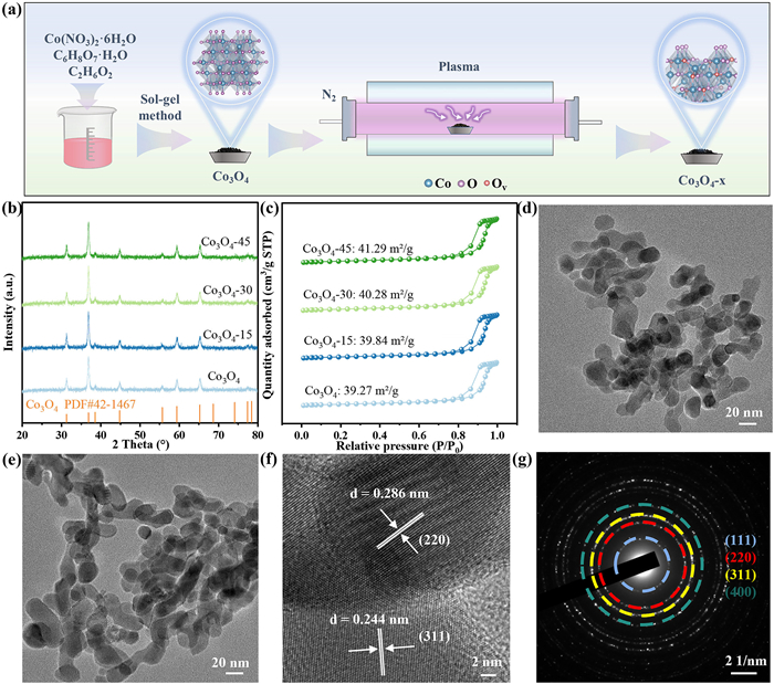
Figure 1.
(a) Synthetic procedure for Co3O4-x. (b) XRD patterns of Co3O4-x. (c) N2 adsorption/desorption isotherms. TEM images of (d) Co3O4 and (e) Co3O4–30. (f) HRTEM image and (g) SAED image of Co3O4–30.

Plasma-induced oxygen vacancy on Co3O4 for enhanced singlet oxygen generation via peroxymonosulfate activation
Keyi Gao , Yunbo Wu , Shulin Shen , Dawei Wang , Yilan Jiang


Antibiotics persist in aquatic environments, posing threats to ecosystems and human health due to hazards such as bioaccumulation and induction of antimicrobial resistance [1,2]. In recent years, persulfate-based advanced oxidation processes (PS-AOPs) have demonstrated remarkable efficiency in degrading organic pollutants [3–5]. As common reactive oxygen species (ROS) in SR-AOP systems, sulfate radical (SO4•−) and hydroxyl radical (•OH) achieve high mineralization rates for contaminants owing to their high redox potential and relatively long half-life [6]. However, in complex aqueous matrices, these radicals are readily scavenged, compromising oxidation performance. In contrast, the non-radical pathway dominated by singlet oxygen (1O2) offers superior selectivity, anti-interference capacity and mild oxidation [7–9]. How to achieve the directional generation of 1O2 in PS-AOPs through the structural regulation of materials is a current research hotspot.
Cobalt-based oxides, exemplified by Co3O4, demonstrate significant catalytic potential in water treatment. Oxygen vacancies (Ov), formed by the departure of lattice oxygen atoms from metal oxides, are recognized as effective active sites for activating peroxymonosulfate (PMS) to generate 1O2 [10–12]. During catalysis, Ov typically functions as electron acceptors, adsorbing PMS to initiate intermediate species (e.g., superoxide radicals, O2•−) that subsequently facilitate 1O2 production via chain reactions [13,14]. Conventional strategies for creating Ov in metal oxides—including ion doping, chemical reduction, and hydrothermal treatment—although effective, still face challenges such as high synthesis temperature requirements and impure products [15–17]. In contrast, plasma etching emerges as a distinct approach, enabling rapid surface defect formation at ambient temperature through interactions with reductive active species or electrons. This technique offers advantages of low energy consumption and minimal byproduct generation [18,19]. Therefore, plasma treatment provides a promising way to construct surface Ov on Co3O4, which may facilitate PMS to generate 1O2.
In this study, Co3O4 was treated with N2 plasma for different durations at room temperature to synthesize Ov-rich Co3O4-x (x denotes the reaction time). Comprehensive characterizations via X-ray photoelectron spectroscopy (XPS), Raman spectroscopy, and solid-state electron spin resonance (ESR) confirmed the successful introduction of Ov. Co3O4-x/PMS systems exhibited significantly enhanced catalytic oxidation performance compared to the pristine-Co3O4/PMS system. Probe experiments confirmed that this enhancement was primarily attributed to the facilitated generation of 1O2, whose steady-state concentration exhibited a significant positive correlation with the improved TC degradation rates. As expected, the incorporation of Ov is shown to be effective in promoting the generation of 1O2. Additionally, Co3O4-x exhibited excellent stability, reusability, and promising applicability in complex water matrices.
The synthesis procedure is illustrated in Fig. 1a. Pristine Co3O4 was prepared via the sol-gel method, followed by thermal treatment in a muffle furnace at 400 ℃ for 2 h. Subsequently, Co3O4 were subjected to plasma treatment under a N2 atmosphere to obtain Co3O4-x (x = 15, 30, 45 min). The phase purity and crystallinity of all samples were confirmed by X-ray diffraction (XRD), as their patterns (Fig. 1b) exhibited diffraction peaks matching well with the standard pattern of Co3O4 (PDF #42–1467) [20]. Furthermore, energy-dispersive X-ray spectroscopy (EDS) mapping images (Fig. S1 in Supporting information) clearly demonstrated the homogeneous distribution of Co and O elements across the material surface. Scanning electron microscopy (SEM) images (Fig. S2 in Supporting information) revealed that all samples exhibit irregular bulk morphologies. Notably, increased surface roughness and porosity of Co3O4-x were observed, attributable to high-energy bombardment induced by plasma. This morphological change was further substantiated by Brunauer-Emmett-Teller (BET) surface area analysis (Fig. 1c), which showed a gradual increase in the specific surface area of Co3O4-x with prolonged plasma treatment time. At the microscopic scale, however, comparison of the Transmission electron microscope (TEM) images between pristine Co3O4 and Co3O4–30 revealed comparable morphologies (Figs. 1d and e). High resolution transmission electron microscope (HRTEM) imaging of Co3O4–30 (Fig. 1f) further resolved its crystalline nature, displaying distinct lattice fringes with spacings of 0.286 nm and 0.244 nm, corresponding to the (220) and (311) planes of the Co3O4 spinel structure, respectively [21]. Additionally, the selected-area electron diffraction (SAED) pattern (Fig. 1g) confirmed the good match between the Co3O4-x and standard Co3O4 [22], indicating that the plasma treatment did not alter the crystal structure of the material.
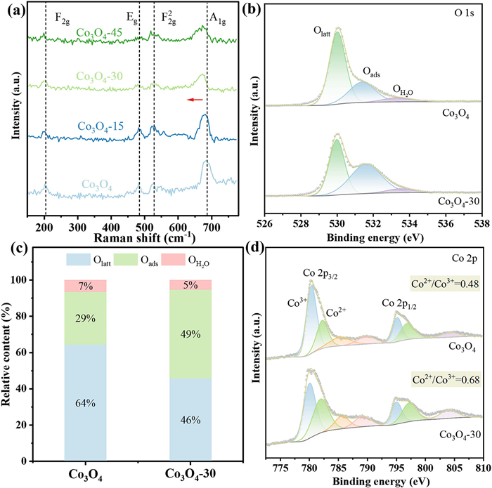
Solid ESR was employed to detect Ov in pristine Co3O4 and Co3O4–30 (Fig. S3 in Supporting information). Compared to pristine Co3O4, Co3O4–30 exhibited a more pronounced ESR signal at a g-factor of 2.003, confirming the successful introduction of Ov [23]. The result was further substantiated by Raman scattering. Each sample exhibited four Raman active modes (F2g, Eg, F2g2, A1g), corresponding to the crystal cube Co3O4 [24,25]. The Raman peak intensity of Co3O4-x weakened and shifted towards lower frequencies (Fig. 2a). Among them, the A1g peak (685 cm−1) associated with the Co-O bond stretching of the octahedral locus showed a relatively significant redshift change, indicating that plasma treatment altered the local electron density and lattice vibration frequency of the Co3O4-x, revealing the introduction of Ov [26]. Furthermore, XPS was performed to monitor the valence state distribution and electronic structure of the samples. The O 1s spectra included three distinct peaks (Fig. 2b): Lattice oxygen (Olatt, ~530.02 eV), adsorbed oxygen species (Oads, ~531.38 eV), and surface hydroxyl groups/water (OH2O, ~533.38 eV) [27–29]. Oads is commonly used as a relative indicator for Ov concentration. The relative content of Oads in Co3O4–30 (48.91%) was significantly higher than that in Co3O4 (28.98%) (Fig. 2c), confirming the increased concentration of Ov on the surface of Co3O4–30. The Co 2p spectra (Fig. 2d) could be deconvoluted into characteristic peaks corresponding to Co2+ (binding energies at 781.89 eV and 796.66 eV) and Co3+ (binding energies at 780.06 eV and 795.03 eV) [25]. Compared to the pristine Co3O4, the Co2+/Co3+ ratio in Co3O4–30 increased from 0.48 to 0.68. The decrease in the average valence state of cobalt is attributed to the transfer of electrons from the O atoms to the Co d-bond center during the formation of Ov [30].
The performance of different catalysts for PMS activation was further evaluated. As shown in Fig. 3a, direct PMS oxidation contributed negligibly to TC removal (< 1%). Although the physical adsorption performance improved slightly with the increase of plasma treatment duration, the adsorption capacity was still very limited (Fig. S4 in Supporting information). In the oxidative degradation stage, the Co3O4-x/PMS systems exhibited significantly higher TC degradation efficiency than the pristine Co3O4/PMS system (Fig. S5 in Supporting information). Specifically, the Co3O4/PMS system only achieved 58.9% TC removal within 30 min, with a first-order reaction kinetic constant (k) of 0.023 min−1. In contrast, the Co3O4–15/PMS, Co3O4–30/PMS, and Co3O4–45/PMS systems demonstrated markedly improved performance, attaining removal efficiencies of 84.7% (k = 0.055 min−1), 93.2% (k = 0.078 min−1), and 92.7% (k = 0.077 min−1), respectively. The catalytic activity of Co3O4-x was significantly enhanced with longer plasma processing time. Given the nearly identical performance of Co3O4–30 and Co3O4–45, it can be inferred that a 30 min-plasma treatment is sufficient to achieve complete formation of Ov on the surface of Co3O4. Besides, key parameters of reaction (PMS dosage, catalyst dosage, pH and TC dosage) were optimized to establish the best degradation conditions (Fig. S6 in Supporting information). Moreover, Comparison of the performance with advanced catalysts in recent researches demonstrated the superior activity of Co3O4–30 for TC degradation via PMS activation (Fig. S7 and Table S1 in Supporting information).
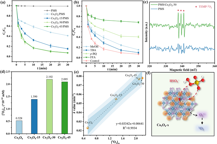
To identify the dominant ROS, quenching experiments and ESR measurements were performed. As shown in Fig. 3b, the impact of tert-butanol (TBA, kTBA, •OH = 6.0 × 10⁸ L mol−1 s−1) and methanol (MeOH, kMeOH, SO4•- = 1.1 × 10⁷ L mol−1 s−1, kMeOH, •OH = 9.7 × 10⁸ L mol−1 s−1) on TC degradation was relatively weak [31,32]. Meanwhile, no significant signal peaks corresponding to DMPO-SO4•− or DMPO-•OH were observed (Fig. S8a in Supporting information), suggesting that the production of SO4•− and •OH radicals was limited in the Co3O4–30/PMS system. In contrast, distinct TEMP-1O2 and DMPO—O2•− signals were also detected (Fig. 3c and Fig. S8b in Supporting information), confirming the presence of 1O2 and O2•−[33,34]. The addition of p-benzoquinone (p-BQ, kp-BQ, O2•− = 8.3 × 10⁸ L mol−1 s−1) and furfuryl alcohol (FFA, kFFA, 1O2 = 1.2 × 10⁸ L mol−1 s−1) to the Co3O4–30/PMS system resulted in significant inhibition of TC degradation, reducing the removal rate by 32% and 60%, respectively [35,36]. The highest quenching efficacy observed with FFA suggests that the dominant degradation mechanism in the Co3O4-x/PMS system is a non-radical pathway involving 1O2. Besides, considering that the redox potential of O2•− is as low as −0.33 V (vs. NHE), which is theoretically difficult to effectively degrade TC [37]. The introduction of trace amounts of p-BQ exerted a significant inhibitory effect on the degradation process, suggesting that O2•− may serve as a key precursor to 1O2 [38].
Moreover, quenching experiments conducted on the pristine Co3O4/PMS system revealed the similar trend, indicating the same types of ROS produced (Fig. S9 in Supporting information). However, the inhibitory effect of FFA on the pristine Co3O4/PMS system was less pronounced, suggesting a lower contribution of 1O2 compared to Co3O4-x/PMS system. Therefore, FFA was further employed as a probe to quantitatively determine the steady-state concentrations of 1O2 ([1O2]ss) generated in each system [39]. As shown in Fig. 3d and Fig. S10 (Supporting information), the Co3O4-x/PMS system generated significantly higher [1O2]ss than Co3O4/PMS system, and the amount of [1O2]ss positively correlated with the TC degradation performance in each system, which confirmed 1O2 originated from plasma-induced Ov and drived the degradation (Fig. 3e). In addition, the influence of O2 and N2 on the degradation reaction can be ignored, thus the path of converting dissolved oxygen to 1O2 was excluded (Fig. S11 in Supporting information) [40]. Based on the above experimental results, it can be inferred that the Ov on the Co3O4-x surface serve as crucial adsorption sites and electron donors, selectively generating 1O2 via PMS activation rather than SO4•− or •OH radicals. Herein, it is speculated that Ov received electrons from PMS and generated O2•−, which functioned dually as intermediates for 1O2 formation and as effective ROS directly attacking TC (Fig. 3f, Eqs. 1–4) [41].
|
|
(1) |
|
|
(2) |
|
|
(3) |
|
|
(4) |
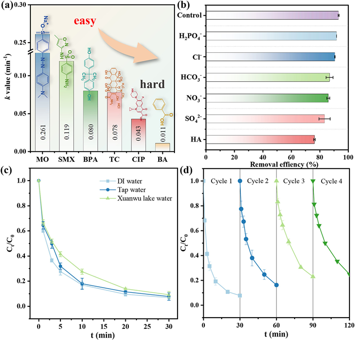
1O2 typically exhibits high selectivity towards organic compounds containing electron-rich moieties [42]. Therefore, six contaminants with varying electron-donating capacities (methyl orange (MO), sulfamethoxazole (SMX), bisphenol A (BPA), TC, ciprofloxacin (CIP), and benzoic acid (BA)) were selected for investigation [43,44]. As shown in Fig. 4a and Fig. S12 (Supporting information), the Co3O4–30/PMS system exhibits significantly higher degradation efficiency for electron-rich organics (MO, SMX, BPA, TC) compared to electron-deficient organics (CIP, BA). The distinct selectivity is attributed to the electrophilic property. Another distinguishing feature of 1O2 is its strong resistance to Inorganic anions. Then, high concentrations of interfering anions (H2PO4−, Cl−, HCO3−, NO3−, SO42−) and humic acid (HA) were introduced (Fig. 4b and Fig. S13 in Supporting information). In the presence of anions, the degradation efficiency of TC remained above 80%. Even with the addition of HA, the removal rate still reached 75%. Among these interfering substances, SO42- as a reaction product, may inhibit the activation of PMS, thereby slightly attenuating TC degradation. In contrast, HA, as a competing pollutant, likely consumed a portion of 1O2, which also contributed to the decrease in TC removal. Overall, the Co3O4–30 material demonstrated favorable environmental tolerance. Furthermore, the adaptability of Co3O4–30/PMS system was evaluated under realistic water matrices, including tap water and lake water. As depicted in Fig. 4c, the Co3O4–30/PMS system maintained high oxidation efficiency in these complex environments, achieving over 90% TC removal within 30 min in both cases. Catalyst recyclability was confirmed over four consecutive cycles, where TC degradation efficiency consistently retained > 70%, demonstrating strong durability for pollutant abatement (Fig. 4d). The slight decrease in the removal rate of TC after four cycles may be attributed to the decline of the active sites on the catalyst surface and the catalytic activity of Co3O4–30 can be restored through simple plasma treatment. Additionally, the XRD pattern reveals that the characteristic peaks of the catalyst remained consistent before and after the reaction (Fig. S14 in Supporting information), confirming the structural stability of the Co3O4–30. Although O 1s XPS analysis shows a slight decrease in the proportion of Oads on cycled Co3O4–30, indicating a reduction of Ov, the Oads content remains higher than that of the pristine Co3O4 (Fig. S15 in Supporting information). Thus, Co3O4–30 maintains relatively high catalytic activity within a certain number of cycles, which can be attributed to its surface-rich Ov. Furthermore, these results provide additional evidence that Ov indeed serves as the key active site for catalyzing PMS to generate 1O2.
In summary, we successfully introduced Ov to the surface of Co3O4-x via a facile and efficient N2 plasma treatment strategy. The Ov rich Co3O4–30/PMS system achieved 93.2% TC degradation within 30 min (k = 0.078 min−1), significantly outperforming the untreated catalyst. The Ov served as key electron acceptors, facilitating the adsorption of PMS to generate the intermediate O2•−, which subsequently which subsequently led to the production of 1O2. Dominated by the 1O2, the Co3O4–30/PMS system exhibited strong oxidative degradation capability toward electron-rich pollutants, demonstrating high selectivity in wastewater purification. The system also showed excellent tolerance to high concentrations of interfering ions and organic matter. As the primary technique employed to engineer catalyst defects, plasma treatment offers a simple and controllable approach for enabling non-radical AOPs for selective pollutant degradation, holding significant potential for practical water purification applications.
The authors declare that they have no known competing financial interests or personal relationships that could have appeared to influence the work reported in this paper.
Keyi Gao: Writing – original draft, Validation, Methodology, Investigation. Yunbo Wu: Writing – original draft, Formal analysis. Shulin Shen: Investigation, Data curation. Dawei Wang: Writing – review & editing, Supervision, Funding acquisition. Yilan Jiang: Writing – review & editing, Supervision, Funding acquisition.
We would like to thank the financial support from Fundamental Research Funds for the Central Universities (No. B250201030), the National Natural Science Foundation of China (Nos. 52370072, 52400031, 52325003), and the Natural Science Foundation of Jiangsu Province (No. BK20242057).
Supplementary material associated with this article can be found, in the online version, at doi:
H.K. Allen, J. Donato, H.H. Wang, et al., Nat. Rev. Microbiol. 8 (2010) 251–259. doi: 10.1038/nrmicro2312
D.G.J. Larsson, C.F. Flach, Nat. Rev. Microbiol. 20 (2022) 257–269. doi: 10.1038/s41579-021-00649-x
D.B. Miklos, C. Remy, M. Jekel, et al., Water Res. 139 (2018) 118–131. doi: 10.1016/j.watres.2018.03.042
K. Yin, Y. Tang, Z. Li, et al., Water Res. 285 (2025) 124130. doi: 10.1016/j.watres.2025.124130
F.N. Anandraj, T.K. Panda, S. Thangarasu, G. Palanisamy, K.E. Neerugatti, Water Res. 284 (2025) 123941. doi: 10.1016/j.watres.2025.123941
S. Giannakis, K.Y.A. Lin, F. Ghanbari, Chem. Eng. J. 406 (2021) 127083. doi: 10.1016/j.cej.2020.127083
J. Zhen, J. Sun, X. Xu, et al., Angew. Chem. Int. Ed. 63 (2024) e202402669. doi: 10.1002/anie.202402669
P.V. Nidheesh, G. Boczkaj, S.O. Ganiyu, et al., Environ. Chem. Lett. 23 (2025) 195–240. doi: 10.1007/s10311-024-01798-0
H. Deng, N. Zhao, J. You, et al., Chin. Chem. Lett. 36 (2025) 110650. doi: 10.1016/j.cclet.2024.110650
Y. Jiang, K. Gao, T. Chen, et al., Chem. Eng. J. 500 (2024) 156532. doi: 10.1016/j.cej.2024.156532
Y. Jiang, K. Gao, Y. Li, et al., Chem. Commun. 60 (2024) 3158–3161. doi: 10.1039/d3cc06100k
J. Qin, Q. Wang, B. Han, et al., Appl. Catal. B 360 (2025) 124538. doi: 10.1016/j.apcatb.2024.124538
Y. Wang, Y. Lin, S. He, S. Wu, C. Yang, J. Hazard. Mater. 461 (2024) 132538. doi: 10.1016/j.jhazmat.2023.132538
L. Lai, H. Zhou, Y. Hong, et al., Chin. Chem. Lett. 35 (2024) 108580. doi: 10.1016/j.cclet.2023.108580
J. Zhang, D. Yan, G. Ding, et al., Angew. Chem. Int. Ed. 64 (2025) e202511448. doi: 10.1002/anie.202511448
X. He, F. Marken, A. Vertova, A. Minguzzi, J. Environ. Manage. 385 (2025) 125583. doi: 10.1016/j.jenvman.2025.125583
Z. Chen, G. Ding, Z. Wang, et al., Adv. Funct. Mater. 35 (2025) 2423213. doi: 10.1002/adfm.202423213
N. Nippatlapalli, A. Ganta, Process Saf. Environ. Prot. 187 (2024) 1454–1470. doi: 10.1016/j.psep.2024.05.009
Z. Ye, L. Zhao, A. Nikiforov, et al., Adv. Colloid Interface Sci. 308 (2022) 102755. doi: 10.1016/j.cis.2022.102755
C. Li, B. Ye, B. Ouyang, et al., Adv. Mater. 37 (2025) 2501381. doi: 10.1002/adma.202501381
Y. Xie, Y. Feng, S. Zhu, et al., Adv. Mater. 37 (2025) 2414801. doi: 10.1002/adma.202414801
K. Wang, T. Zhao, N.Q. Ren, S.H. Ho, Water Res. 265 (2024) 122304. doi: 10.1016/j.watres.2024.122304
X. Wang, M. Wu, B. Liu, et al., Chem. Eng. J. 519 (2025) 165473. doi: 10.1016/j.cej.2025.165473
J. Zou, Y. Zou, H. Wang, et al., Chin. Chem. Lett. 34 (2023) 107378. doi: 10.1016/j.cclet.2022.03.101
Y. Chen, Q. Li, R. Su, et al., Water Res. 282 (2025) 123765. doi: 10.1016/j.watres.2025.123765
S. Wang, J. Kang, P. Yan, et al., Appl. Catal. B 342 (2024) 123419. doi: 10.1016/j.apcatb.2023.123419
G. Zhu, W. Tan, T. Gu, A. Dou, Q. Xu, Appl. Surf. Sci. 709 (2025) 163742. doi: 10.1016/j.apsusc.2025.163742
G. Ding, J. Zhang, D. Yan, et al., Nano Lett. 25 (2025) 8984–8992. doi: 10.1021/acs.nanolett.5c01259
Y. Xiao, G. Ding, J. Tao, et al., Nat. Commun. 16 (2025) 7476. doi: 10.1038/s41467-025-62369-7
J. Hu, B. Qian, X. Zeng, et al., J. Mater. Chem. A 9 (2021) 16489–16499. doi: 10.1039/d1ta03963f
L. Gao, Y. Guo, J. Zhan, G. Yu, Y. Wang, Water Res. 221 (2022) 118730. doi: 10.1016/j.watres.2022.118730
Z. Chen, D. Yan, X. Wang, et al., ACS Catal. 15 (2025) 13568–13580. doi: 10.1021/acscatal.5c02889
H. Han, M. Chen, C. Sun, et al., Water Res. 268 (2025) 122666. doi: 10.1016/j.watres.2024.122666
K. Yin, J. Yang, Y. Li, Q. Li, X. Xu, Chin. Chem. Lett. 35 (2024) 109847. doi: 10.1016/j.cclet.2024.109847
X. Li, X. Zhang, J. Lang, et al., Sci. Bull. 69 (2024) 3867–3875. doi: 10.1016/j.scib.2024.09.046
Y. Guo, J. Long, J. Huang, G. Yu, Y. Wang, Water Res. 215 (2022) 118275. doi: 10.1016/j.watres.2022.118275
L. Wu, Z. Sun, Y. Zhen, et al., Environ. Sci. Technol. 55 (2021) 15400–15411. doi: 10.1021/acs.est.1c04600
Q. Fang, H. Yang, S. Ye, et al., Water Res. 245 (2023) 120614. doi: 10.1016/j.watres.2023.120614
H. Wang, D. Wang, C. Sun, et al., Appl. Catal. B 364 (2025) 124854. doi: 10.1016/j.apcatb.2024.124854
Y. Yao, J. Zhang, Y. Wang, et al., Chin. Chem. Lett. 35 (2024) 109633. doi: 10.1016/j.cclet.2024.109633
S.H. Zhou, R.D. Wang, Y. Yang, et al., Chem. Eng. J. 513 (2025) 163031. doi: 10.1016/j.cej.2025.163031
Y. Zhao, L. Yu, C. Song, et al., Environ. Sci. Technol. 56 (2022) 10710–10720. doi: 10.1021/acs.est.2c01759
M. Ao, J. Wei, C.S. He, et al., Chin. Chem. Lett. 36 (2025) 109882. doi: 10.1016/j.cclet.2024.109882
C. Jin, B. Han, C. Luo, et al., Water Res. 287 (2025) 124420. doi: 10.1016/j.watres.2025.124420

Figure 1 (a) Synthetic procedure for Co3O4-x. (b) XRD patterns of Co3O4-x. (c) N2 adsorption/desorption isotherms. TEM images of (d) Co3O4 and (e) Co3O4–30. (f) HRTEM image and (g) SAED image of Co3O4–30.

Figure 2 (a) Raman spectra of Co3O4, Co3O4–15, Co3O4–30 and Co3O4–45. (b) O 1s XPS spectrum of Co3O4 and Co3O4–30. (c) Corresponding proportion of different O species in Co3O4 and Co3O4–30. (d) Co 2p XPS spectrum of Co3O4 and Co3O4–30.

Figure 3 (a) The degradation efficiency of TC in different reaction systems. (b) Quenching experiments in Co3O4–30/PMS system. (c) ESR spectrum of 1O2 in Co3O4–30/PMS system. (d) [1O2]ss in different reaction systems (mM = mmol/L). (e) The relationship between the [1O2]ss of and k value in different systems. (f) Generation pathway of 1O2 in Co3O4-x/PMS systems. Reaction conditions: [catalysts] = 0.2 g/L, [TC] = 20 mg/L, [PMS] = 0.2 g/L, [MeOH] = [TBA] = 100 mmol/L, [p-BQ] = 10 mmol/L, [FFA] = 50 mmol/L, pH 7.0.

Figure 4 (a) k values of different pollutants in Co3O4–30/PMS system. (b) Effect of inorganic ions and HA on TC degradation in Co3O4–30/PMS system. (c) Performance of the Co3O4–30/PMS system for TC removal in distinct water bodies. (d) TC degradation efficiency over four cycles in Co3O4–30/PMS system. Reaction conditions: [catalysts] = 0.2 g/L, [pollutants] = 20 mg/L, [PMS] = 0.2 g/L, [anions] = 50 mmol/L, [HA] = 5 mg/L, pH 7.0.

 扫一扫看文章


扫一扫关注我们
 DownLoad:
 下载:
下载:
 下载:
下载: