Received Date:
22 August 2025 Accepted Date:
11 November 2025 Revised Date:
10 November 2025 Available Online:
15 June 2026
Abstract:
Metal-organic frameworks (MOFs) and their derivatives have emerged as promising platforms for constructing heterojunctions in photocatalytic CO2 reduction (PCR). This review systematically summarizes the latest research progress in MOFs and their derivative heterostructures for PCR, focusing on material design, underlying mechanisms, and diverse applications. Besides, this review, by introducing various synthesis methods, emphasizes the significance of controllable synthesis strategies. Furthermore, the in-situ characterization techniques and theoretical calculations in photocatalysis are introduced and summarized, including the study of the morphology and chemical structure of photocatalysts, the transfer of photogenerated charges, spatial distribution, and surface reaction pathways. Systematic reviews of the advantages and disadvantages, features, and applications of various types of MOFs and their derivative heterostructures are conducted in accordance with the band arrangement characteristics. In addition, the discussion scope is expanded to related catalytic systems, including electrocatalysis, photoelectrocatalysis, and photothermal catalysis, fully demonstrating the multifunctionality of MOFs and their derivative heterostructures. Finally, future research directions are proposed from aspects such as material design and synthesis, performance optimization and mechanism research, correlation with practical applications, as well as the interdisciplinary collaboration. We hope it can provide valuable references for the rational design of high-performance MOFs and their derivative heterostructures materials with the wide range of applications.
The significant rise in anthropogenic CO2 emissions, which has resulted in severe energy crises and environmental degradation, is a direct consequence of the excessive consumption of non-renewable energy resources [1–8]. Industrial activities such as electricity generation, transportation, and manufacturing rely heavily on coal, oil, and natural gas, releasing a large amount of CO2. Agricultural activities, through processes such as mechanized production driven by fossil energy, synthesis of fertilizers and pesticides, burning of crop residues, and changes in land use directly or indirectly increase CO2 emissions, while releasing potent greenhouse gases such as methane (CH4) and nitrous oxide (N2O), thereby exacerbating global warming [9–14]. The Intergovernmental Panel on Climate Change (IPCC) reports with high confidence that aggregate net CO2 emissions from 1850 to 2019 reached 2400 ± 240 GtCO [15]. Notably, over half of these emissions were released prior to 1990, while the subsequent three decades (1990–2019) accounted for approximately 42%. By 2019, atmospheric CO2 concentrations had attained 410 ppm, exceeding levels observed in the preceding two million years [16]. Concurrently, CH4 and N2O concentrations surpassed those documented over the last 800,000 years. It should mean annual CO2 emissions during 2020–2030 persist at 2019 levels, the resultant cumulative output would deplete nearly 50% of the remaining carbon budget for limiting warming to 1.5 ℃, and consume over two-thirds of the budget for 2 ℃ [17]. This accelerated emission trajectory is a primary driver of anthropogenic climate change, as evidenced by the thawing of Arctic permafrost and the accelerated occurrence of extreme weather events, such as unprecedented heatwaves and cyclones. These extreme climate changes have threatened the yield and quality of crops. Specifically, excessive CO2 levels have further exacerbated the vulnerability of agricultural ecosystems by altering the structure of soil microbial communities, accelerating the decomposition of organic matter, and weakening the carbon sink function [18,19].
Photocatalytic CO2 reduction emulates natural photosynthetic processes by transforming solar energy into chemical bond energy via catalytic materials. This sustainable approach offers operational cost efficiency, minimal energy consumption, and environmentally benign conversion of CO2 to energy-dense fuels [20,21]. The reaction is fundamentally centered around the photocatalyst. Its band structure determines the range of light capture, the efficiency of carrier separation affects the utilization of electrons, and the atomic coordination environment of the surface-active sites directly regulate the activation energy for CO2 adsorption and the conversion pathways of key intermediates, ultimately determining the efficiency and product selectivity of the photocatalytic reaction [22,23]. Consequently, developing materials with superior catalytic activity and ecological compatibility is paramount for maximizing resource utilization toward authentic energy conservation and emission reduction objectives.
However, traditional semiconductor photocatalysts, such as metal sulfides and metal oxides, often have some inherent limitations, including rapid recombination of photogenerated charge carriers, limited active sites, and insufficient carbon dioxide adsorption capacity [24]. In this context, metal-organic frameworks (MOFs) stand out as a highly promising material category, thanks to their unique structural characteristics, which offer significant advantages. MOFs are a type of crystalline porous solid that are produced through the coordination-driven assembly of metal ions or clusters and multitopic organic linkers [25–33]. Since their first report in 1995 [34], their development has undergone a leapfrog advancement from structure exploration to function-oriented design. Early research emphasized the exceptional specific surface area and tunable porosity of MOFs, highlighting their advantages in gas adsorption and molecular separation applications. The MOFs-derived materials, which are obtained through the thermal treatment or chemical treatment of MOFs precursors, exhibit exceptional thermal and chemical stability while retaining a hierarchical pore structure [35–38]. Over the preceding decade, the strategic focus of MOFs and their derivative functional engineering has progressively aligned with artificial photosynthesis research, catalyzing a shift toward photocatalytic applications. The main advantage of MOFs over other photocatalysts lies in their unparalleled structural tunability. This characteristic is achieved by carefully selecting metal nodes and organic linkers, allowing for precise control of the band gap and light capture performance [39–41]. MOFs with a highly porous framework and open channels not only facilitate the absorption of a large amount of carbon dioxide but also ensure the accessibility of active sites and promote the transport of reactants and products. Although pure metal-organic framework materials may have low photoreactivity and poor stability, they possess the ability to be functionalized in situ or after synthesis, allowing the introduction of functional groups or uncoordinated metal centers, thereby forming a large number of catalytic sites [42–44]. These outstanding properties make metal-organic framework materials highly attractive for photocatalytic carbon dioxide reduction [45–47]. Within this domain, the rational design of MOFs and their derivatives heterojunction architectures offers a promising approach to overcome intrinsic limitations associated with conventional semiconductor photocatalysts shown in Fig. 1 [48–59]. Unlike the high recombination rate of photogenerated carriers and insufficient active sites in single-component MOFs, heterojunctions can achieve spatial separation and directional migration of electrons and holes through interface band matching, significantly improving the selectivity and efficiency of photocatalytic CO2 reduction (PCR) reactions [60].
Figure 1
Figure 1.
Timeline of the development of MOFs and their derivatives heterostructures. Reproduced with permission [48], Copyright 2014, Elsevier; [49], Copyright 2015, Wiley; [50], Copyright 2016, American Chemical Society; [51], Copyright 2017, Elsevier; [52], Copyright 2018, Wiley; [53], Copyright 2019, Elsevier; [54], Copyright 2020, Elsevier; [55], Copyright 2021, Wiley; [56], Copyright 2022, Springer Nature; [57], Copyright 2023, Elsevier; [58], Copyright 2024, Elsevier; and [59], Copyright 2025, Elsevier.
As illustrated in Fig. 2, MOFs and their derivatives heterostructure photocatalysts have been demonstrated the unique capabilities in converting anthropogenic CO2 emissions. The CO2 emissions from human activities have led to excessive concentration of CO2 in the global atmosphere and an increase in the global average temperature [61,62]. This carbon imbalance is expected to be resolved through solar-driven photocatalytic systems. In these systems, the designed MOFs and their derivatives heterostructure catalysts can utilize visible light to activate the multi-electron reduction reactions of captured CO2. The substances such as methanol, formic acid, carbon monoxide and methane produced by the PCR reaction can be used as renewable raw materials in industrial processes. This integrated approach has constructed a carbon-neutral cycle: industrial emissions are reconverted through photochemical reactions into synthetic fuels and chemical precursors, replacing fossil fuel equivalents and enabling a sustainable carbon energy cycle.
Figure 2
Figure 2.
The schematic diagram of MOFs and their derivatives heterostructure photocatalysts participating in the CO2 cycle.
In recent years, the research interest in MOFs and their derivatives heterostructure photocatalysts has significantly increased [63–66], and the number of related papers has continued to rise (Fig. 3). Among them, studies focusing on the application of PCR reduction have been particularly prominent, reflecting the academic community’s high attention to the potential value of MOFs and their derivatives heterostructure in artificial photosynthesis. This trend indicates that with the deepening of material design and mechanism research, MOFs and their derivatives heterostructures are gradually expanding from basic exploration to functional applications, becoming one of the important research directions for solving energy and environmental problems. However, current research still faces key challenges: unclear interface regulation mechanisms, lack of universal strategies for constructing efficient active sites, and insufficient research on the correlation of multi-scale catalytic performance [67–75]. Therefore, systematically summarizing the synthesis methods, efficient construction, and in-depth photocatalytic mechanisms of MOFs and their derivatives heterostructure is crucial for promoting the development of this field.
Figure 3
Figure 3.
Number of publications of MOFs and their derivatives heterostructure photocatalysts for CO2 reduction in the last 8 years (Source: Web of Science).
This review systematically summarized the research progress of MOFs and their derivatives heterostructures in the field of PCR, conducting multi-dimensional discussions from material design and mechanism to diverse applications. The research framework focuses on controllable synthesis strategies, using in-situ characterization and theoretical calculations to clarify the structural-activity relationship of the heterojunction interface charge separation dynamics and reaction intermediate conversion. Besides, MOFs and their derivatives heterostructures are categorized into Type-Ⅱ, Z-scheme, Schottky junction, and S-scheme types based on distinct band alignment characteristics, enabling a systematic discussion and comparison of their differences in CO2 activation and product selectivity over the PCR process. Subsequently, the discussion is extended to other applications, including electrocatalytic, photoelectrocatalytic, and photothermal catalytic systems. Finally, it presents the prospects for MOFs and their derivatives heterostructures in the field of PCR from various aspects such as material design and synthesis, performance optimization and mechanism research, and the correlation with practical applications, providing a reference for rational design of efficient catalysts (Fig. 4).
Figure 4
Figure 4.
Overview of research on MOFs and their derivatives heterostructures in this review.
2.
The synthetic strategies of MOFs and their derivatives heterostructure photocatalysts
It is reported that MOFs are periodic porous crystalline materials formed by the coordination bonds between inorganic metal centers and organic ligands. MOF derivatives include modified forms achieved through defect engineering, element doping, or integration with functional components. Due to their comprehensive advantages, including structural tunability, extremely high specific surface area, robust stability and enhanced redox activity through derivative modification, MOFs and their derivatives can achieve highly specific and selective synthesis, and can be adjusted for their photophysical properties for use in photocatalytic applications [76,77]. The synthesis methods of MOFs and their derivatives heterostructures are diverse, including hydrothermal method, solvothermal method, electrostatic self-assembly method and high-temperature calcination method [78,79]. By synthesizing MOFs and their derivatives heterostructures through different methods and precisely controlling factors such as the type of solvent, temperature and pressure during the synthesis process, it will directly affect the defect density, interface binding strength and active site distribution of MOFs and their derivatives heterostructures [80–82]. These factors are crucial for optimizing the photocatalytic performance. The following paragraphs provide a brief description of the general synthesis method.
2.1
Hydrothermal method
The hydrothermal method is widely used in the synthesis of MOFs and their derivatives heterostructure photocatalysts. This method has the advantages of simplicity, high level of automation, wide range of operating conditions, high synthetic yield and easy adjustability of reaction conditions (such as temperature, starting materials and pH) [83–86]. By adjusting the parameters during synthesis, MOFs and their derivatives heterostructures with controllable size and structure can be obtained. Specifically, in the process of constructing MOFs and their derivatives heterostructures by hydrothermal method, the high-temperature and high-pressure water environment provides a high concentration of reactant ions and molecules, accelerating diffusion and reaction kinetics, causing the dissolution, diffusion and directional crystallization of metal precursors and ligands, and forming the ready MOFs and their derivatives heterostructures [87–89].
For instance, Zhao et al. [90] fabricated NH2−MIL-125(Ti) (NM) with tailored crystal surfaces and Co3O4@NH2−MIL-125(Ti) (C–NM) composites with different Co3O4 loading via hydrothermal synthesis (Fig. 5a). Through modulation of titanium precursor and ligand concentrations, disc-shaped and octahedral NM morphologies were achieved. Subsequent incorporation of Co3O4 nanoparticles into these frameworks yielded C–NM heterostructures. The introduction of narrow-bandgap Co3O4 cocatalyst effectively narrows the composite’s bandgap, thereby establishing enhanced visible-light harvesting and photocatalytic efficiency. Furthermore, Gui et al. [91] employed a multi-step strategy to fabricate a porous ZnS/TiO2 heterostructure. Initially, a ZIF-8/NH2−MIL-125(Ti) composite was formed by growing ZIF-8 nanoparticles on NH2−MIL-125(Ti) templates at room temperature. The final heterostructure was then derived from this MOF-on-MOF composite through a key hydrothermal reaction with thiourea (Fig. 5b).
Figure 5
Figure 5.
The synthetic method of (a) NM and C–NM. Reproduced with permission [90]. Copyright 2025, Elsevier. (b) ZnS/TiO2. Reproduced with permission [91]. Copyright 2023, Elsevier. (c) NM101@BMO. Reproduced with permission [101]. Copyright 2023, Elsevier. (d) TTCOF/NUZ. Reproduced with permission [102]. Copyright 2022, American Chemical Society.
Overall, the hydrothermal method performs outstandingly in the preparation of materials with high crystallinity. It takes advantage of the characteristics of a closed system to ensure the accuracy of the stoichiometric ratio, avoid impurity contamination, and precisely control the morphology of the material by adjusting the reaction parameters. However, its limitations include the difficulty in mechanism research caused by the invisibility of the reaction process and the possible structural instability of the product due to fluctuations in conditions [92].
2.2
Solvothermal synthesis method
The solvothermal method has greatly increased the application fields and synthetic possibilities of the hydrothermal method by replacing the reaction medium from water to organic solvents or mixed solvent systems, and has become one of the important methods for preparing new functional materials [93–96]. Because many organic ligands and MOFs have higher solubility, greater stability and more active reactions in organic solvents, and the physical and chemical properties such as polarity and boiling point of organic solvents are more diverse, it provides more possibilities for the fine regulation of the formation of heterostructures. Commonly used organic solvents include N,N-dimethylformamide (DMF), N,N-diethylformamide (DEF), dimethyl sulfone (MSM) and CH3OH [97–100], etc. For example, Feng et al. [101] successfully constructed a new type of NH2−MIL-101(Fe)@Bi2MoO6 S-scheme heterojunction using DMF as the solvent by solvothermal method (Fig. 5c). Firstly, NH2-BDC and FeCl3·6H2O were dissolved in DMF and ultrasonically treated for 1 h. Subsequently, different proportions of Bi2MoO6 (BMO) powder and NH2−MIL-101(Fe) (NM101) were added. The mixed solution was transferred to a reactor lined with polytetrafluoroethylene (PTFE) and heated at 110 ℃ for 24 h. After cooling to room temperature, NM101@BMO composites were obtained by centrifugation, washing and drying process. This method enables BMO nanoparticles to grow uniformly on the NM101 octahedron, and the interface between the two is in close contact. The resultant heterojunctions revealed significantly enhanced activity for CO2 photoreduction.
The solvothermal method is also widely used in the preparation of covalent organic framework/metal-organic framework (COF/MOF) heterojunctions. In this study, Niu et al. [102] synthesized olefin linked covalent organic frameworks (TTCOF) and NH2-UiO-66(Zr) (NUZ) respectively by the dissolution heat method, and then combined TTCOF with NUZ by in-situ solvothermal method (Fig. 5d). Different amounts of TTCOF were dispersed in DMF, mixed with ZrCl4, NH2-BDC and CH3COOH, and reacted overnight at 120 ℃ to obtain x% TTCOF/NUZ. The inherent n-type characteristics and Fermi level (EF) disparity between TTCOF and NUZ materials established favorable conditions for constructing an S-scheme heterostructure. Such configuration facilitates the generation of an internal electric field, which promotes efficient interfacial charge transfer between constituent components, ultimately enhancing photocatalytic redox performance.
Compared with the hydrothermal method, the solvent-thermal method can synthesize some MOFs and their derivatives heterostructure materials that are difficult to dissolve or stabilize in water. Meanwhile, it can better control the reaction rate and selectivity, which is conducive to improving the quality and performance of the product. However, the solvothermal method also has some problems. Such as, due to the relatively high cost of organic solvents and their usual toxicity, their recycling and treatment are rather difficult, which may cause harm to the environment and human health.
2.3
Electrostatic self-assembly method
Electrostatic self-assembly is a method that achieves the self-assembly of materials based on the electrostatic attraction between substances with opposite charges [103,104]. This method shows unique advantages in the preparation of MOFs and their derivatives heterostructure, especially core-shell structures, hybrid particles or thin film heterostructures [105]. One of the most representative works is that Zhu et al. [106] reported the method for preparing Cu-MOF/Cd0.5Zn0.5S composite photocatalysts through electrostatic self-assembly technology (Fig. 6a). This synthesis process is as follows: the Cd0.5Zn0.5S nanoparticles were dispersed in ethanol and ultrasonically treated to form a uniform dispersion. Next, different masses of Cu-MOF were added to the above dispersion, subjected to ultrasonic treatment again and stirred for 1 h. Afterwards, the self-assembly of Cu-MOF with Cd0.5Zn0.5S was achieved through electrostatic interaction. Finally, the mixture was dried to obtain the Cu-MOF/Cd0.5Zn0.5S composite catalyst. This method regulates the electrostatic interaction between components, enabling Cu-MOF and Cd0.5Zn0.5S to form a close interface contact, achieving the uniform construction of S-Scheme heterojunctions, significantly improving the charge separation efficiency, and increasing the number of active sites, providing an effective way for the optimization of photocatalytic performance.
Figure 6
Figure 6.
The synthetic method of (a) Cu-MOF/Cd0.5Zn0.5S. Reproduced with permission [106]. Copyright 2023, Elsevier. (b) CABB/Ni-MOF. Reproduced with permission [110]. Copyright 2023, Royal Society of Chemistry. (c) MTO/g-C3N4. Reproduced with permission [115]. Copyright 2021, Elsevier. (d) ZnO/BiOBr. Reproduced with permission [116]. Copyright 2025, Elsevier.
It can be seen that the electrostatic self-assembly strategy shows significant advantages in constructing efficient heterojunction photocatalysts. By promoting interfacial contact and charge separation, it can effectively enhance catalytic performance [107–109]. Employing this foundational principle, Jiang and collaborators [110] fabricated an inorganic–organic Cs2AgBiBr6 (CABB)/Ni-MOF hybrid photocatalyst via electrostatic self-assembly process (Fig. 6b), demonstrating the enhanced efficacy in PCR. In brief, 6 mg of Ni-MOF was dispersed in 10 mL of C5H8O2via ultrasonication for 10 min. Subsequently, a defined quantity of CABB was introduced into the mixture under continuous agitation. The resulting suspension was sealed and subjected to constant stirring over a 10-h period. The solid product was then isolated through centrifugation, followed by vacuum drying at 50 ℃ for 12 h, ultimately yielding the CABB/Ni-MOF composite. Systematic studies suggested an established S-scheme heterojunction at the CABB/Ni-MOF interface, which concurrently promoted the segregation of photogenerated charge carriers while maintaining the composite’s elevated redox potential. The Ni-MOF component additionally facilitated CO2 adsorption to augment surface reaction kinetics. These synergistic attributes culminated in substantially improved CO2 photoreduction performance.
Similarly, Liu et al. [111] prepared the bimetallic porphyrin heterojunction CuTCPP(Cu)/CuTCPP(Fe) through a simple electrostatic self-assembly method based on π-π stacking interactions. After modifying it with C19H42BrN at pH 4, the surface of CuTCPP(Cu) carried positive charges, enabling it to self-assemble with CuTCPP(Fe) through electrostatic interactions. The positively charged CuTCPP(Cu) was continuously mixed with the negatively charged CuTCPP(Fe) in an aqueous suspension for 10 h. After centrifugal separation and drying at room temperature, a tightly connected CuTCPP(Cu)/CuTCPP(Fe) heterojunction was obtained. Compared with the unmodified simple mixture, the photoluminescence intensity of the heterojunction was significantly reduced, confirming the existence of electrostatic interactions.
However, the electrostatic self-assembly method also has some challenges. The process of surface charge modification may have a certain impact on the inherent properties of the material. It is necessary to select appropriate modification methods and reagents to minimize the adverse effects on the material performance as much as possible. The process of electrostatic self-assembly is influenced by multiple factors, such as the pH value of the solution, ionic strength, and temperature. Changes in these factors may lead to unstable assembly results. In addition, at present, the electrostatic self-assembly method still has certain difficulties in the large-scale preparation of MOFs and their derivatives heterostructure materials, and further research and development of more efficient and reliable assembly technologies are needed.
2.4
High-temperature calcination
The high-temperature calcination method entails subjecting a mixture containing MOF precursors and other functional materials to heat treatment at high temperatures. This process results in the precursors to undergo decomposition, oxidation–reduction, and other reactions, thereby forming MOFs and their derivatives heterostructures. In addition, high-temperature environments can also promote the diffusion and interaction among different components, thereby achieving the formation of heterojunctions [112,113]. The high-temperature calcination method is relatively simple to operate and does not require complex equipment and technology. It is widely used in the synthesis of MOFs and their derivatives heterostructures.
For instance, Yang et al. [114] synthesized A-TiO2/β-Bi2O3 heterojunctions with abundant oxygen vacancies (OV) via high-temperature calcination. These structures retained the parental MOF-derived cake-like morphology, which significantly increased active site exposure. Under visible-light irradiation, the synergistic interaction between OV and heterojunctions enhanced photocatalytic performance, manifested through intensified photoresponse, improved carrier separation efficiency, and suppressed electron-hole recombination. Similarly, Li et al. [115] developed an S-scheme heterojunction photocatalyst by integrating MOF-derived titanium dioxide (MTO) with porous g-C3N4. The synthesis involved calcining NH2−MIL-125(Ti) at 550 ℃ for 2 h to obtain MTO, while g-C3N4 precursors were prepared via salt-template methodology. Subsequent mixing of MTO with varying g-C3N4 ratios followed by 550 ℃ calcination for 2 h yielded MTO/g-C3N4 composites (Fig. 6c). This band-aligned heterojunction architecture simultaneously inhibits charge recombination and preserves strong redox capacity.
The high-temperature calcination method can also prepare MOFs and their derivatives heterostructures with high crystallinity and good stability. Shen et al. [116] constructed an S-scheme ZnO/BiOBr heterojunction photocatalyst derived from MOFs through calcination (Fig. 6d). Specifically, dissolve 0.25 g of Bi-MOF and varying ratios of ZIF-8 in 25 mL of water, followed by the addition of 0.005 mol of ammonium bromide to the solution with thorough stirring. Finally, the resulting solution was then transferred to an oil bath and subjected to agitation at a temperature of 90 ℃ for a duration of 1 h. Following this step, the solution was subjected to three rounds of washing with DI water and subsequently dried at 70 ℃. The resulting powder was further treated by heating in air. It was heated at a rate of 1 ℃/min and sustained at a temperature of 450 ℃ for 2 h to yield the ZnO/BiOBr catalyst. Their research demonstrated that within this composite, dodecahedral ZnO particles established robust adhesion to BiOBr hollow rods. This configuration simultaneously introduced oxygen vacancies and strengthened interfacial interactions. The special heterojunction structure and well-aligned energy band potentials between ZnO and BiOBr made it possible for close contact, lots of active sites, and fast charge transfer, all of which are necessary for PCR to work. Separately, Ma et al. [117] developed a stable UiO66-NH2@In2O3 heterostructure by integrating UiO66-NH2 with In2O3 nanoparticles, followed by calcination at 250 ℃ for 4 h to achieve uniform indium doping. In this optimized heterostructure, the extensive surface area of UiO66-NH2 and the heterojunction formation with In2O3 are the sources to collectively facilitate the mobility of charge carriers, which improved PCR performance dramatically. These results underscore the synergistic interplay between UiO66-NH2 and In2O3 offered the design principles for advanced photocatalysts in energy and environmental remediation applications.
High-temperature calcination can optimize the structure and properties of materials, enhancing their heat resistance, chemical stability and mechanical strength. However, the high-temperature calcination method also has some disadvantages. High-temperature calcination may lead to sintering and agglomeration of materials, affecting their properties such as specific surface area and porosity. Secondly, during the calcination process, the decomposition of organic matter may produce some gaseous by-products. These gases may cause defects or holes inside the material, affecting its structure and performance.
2.5
Other synthetic methods
In addition to the above four synthetic methods, there are many other strategies that can be used to construct MOFs and their derivatives heterostructures. These methods often combine specific techniques or take advantage of the special properties of MOF materials [118–122]. Table 1 [83,107,110,119,123–137] briefly lists some synthesis methods for the heterostructures of MOFs and their derivatives. Meanwhile, in Table S1 (Supporting information), the advantages and limitations, applicable conditions, and related research examples of different synthesis methods are compared.
Table 1
Table 1.
Synthesis methods of MOFs and their derivatives heterostructures.
The in-situ growth strategy for synthesizing MOFs and their derivatives heterostructures achieves atomic-level interface contact and strong coupling between heterocomponents through direct nucleation and directional growth within the reaction system. It features tight interface bonding and uniform and controllable structure. For instance, Liu et al. [138] successfully prepared a series of Cu-doped ZIF-67Co and Bi4O5Br2 nanostructured composite photocatalysts by adopting ion doping and in-situ growth strategies (Fig. 7a). Firstly, by adjusting the molar ratio of Co2+ and Cu2+, ZIF-67CoCu nanocubes with different Cu doping ratios were synthesized. Subsequently, the prepared ZIF-67CoCu was combined with Bi4O5Br2 nanosheets in different mass ratios. The ZIF-67CoCu nanocubes were grown on the surface of Bi4O5Br2 nanosheets through in-situ growth to form heterogeneous structures. By optimizing the reaction conditions, the optimal Cu doping ratio and composite ratio were determined, and a 1% ZIF-67CoCu(1:1)/Bi4O5Br2 composite photocatalyst with excellent PCR performance was prepared.
Figure 7
Figure 7.
Other synthetic method of MOFs and their derivatives heterostructure (a) ZIF-67-CoCu/Bi4O5Br2. Reproduced with permission [138]. Copyright 2024, American Chemical Society. (b) Zn-MOF/BVON. Reproduced with permission [127]. Copyright 2022, Elsevier. (c) HT-In2O3/MⅡIn2S4. Reproduced with permission [141]. Copyright 2022, American Chemical Society. (d) Ni@MOF/BVO. Reproduced with permission [125]. Copyright 2022, Wiley.
The hydroxy–induced assembly method features mild reaction conditions, simple operation procedures, rapid reaction speed and high yield. Zhao et al. [127] employed hydroxyl-induced assembly to integrate Zn-MOF with BiVO4, constructing a dimensionally congruent 2D/2D S-scheme heterojunction (Zn-MOF/BVON). As illustrated in Fig. 7b, the synthesis commenced with the preparation of BiVO4 nanosheets (BVON) via a hydrothermal method. Subsequent washing, drying, and brief calcination (450 ℃, 8 min) yielded ultra-thin BVON. Secondly, ultra-thin Zn-MOF nanosheets were synthesized by solvent thermal method. Finally, BVON and Zn-MOF were integrated by hydroxyl-induced assembly strategy. Accordingly, the two were ultrasonically dispersed in C2H5OH, and the solvent was evaporated under water bath at 70 ℃ to promote the formation of chemical bonds between the -OH on the surface of BVON and the zinc nodes of the porphyrin ligands in Zn-MOF, thereby constructing a closely contacting dimension-matched 2D/2D heterojunction interface. This structurally aligned configuration enhanced charge separation efficiency and provided abundant catalytic active sites, significantly improving CO2 conversion performance [139].
The low-temperature reflux synthesis method offers distinct advantages by facilitating reactions under mild thermal conditions, thereby suppressing undesirable side reactions and material decomposition common in high-temperature processes [140]. In the study by Bariki et al. [141], it was demonstrated that a hierarchical In2O3/MⅡIn2S4 (MⅡ: Ca, Mn, Zn) hollow tubular (HT) heterostructure with a layered structure was rationally designed by growing ternary metal sulfides (MⅡIn2S4) nanosheets on the surface solution of MIL-68(In) (Fig. 7c). For example, by dispersing a certain amount of HT-In2O3 in 40 mL of deionized water (pH 3), and then adding 55 mg of ZnCl2, 178 mg of InCl3, and 130 mg of L-glutathione reduced, ZnIn2S4 nanosheets anchored on the surface of HT-In2O3 were prepared. The resulting mixture was vigorously stirred for 1 h, then placed in an oil bath at 80 ℃ for a reaction for 4 h. The obtained yellow product was washed multiple times with ethanol to remove unnecessary impurities, and then vacuum-dried at 50 ℃. The obtained HT-In2O3/ZnIn2S4 composite material was further calcined at 150 ℃ in an inert atmosphere for 3 h to achieve better interface contact.
Hydrogen bond-induced assembly is a technique that achieves self-assembly by utilizing intermolecular hydrogen bond interactions. It has the advantages of simplicity, high efficiency and good repeatability, etc. Zhao et al. [125] utilized a cup-shaped microscopic structure composed of Ti(Ⅳ)-oxo nodes and three connected carboxyl groups to achieve the immobilization of a large number of single Ni(Ⅱ) sites (Ni@MOF) within the monolayer coordination layer of Ti2(H2dobdc)3 MOF (NTU-9). By using a hydrogen bond-induced assembly method, Ni@MOF was coupled with bismuth vanadate (BiVO4, BVO) nanosheets, thereby obtaining a wide-spectrum two-dimensional heterojunction (Fig. 7d). Specifically, first, NTU-9 was prepared using isopropyl titanate and H4dobdc as raw materials through solvothermal method. Secondly, in order to obtain the thinnest NTU-9 nanosheets to achieve the expected increase in surface area and shortening of charge transfer distance, isopropanol was selected as the solvent. The interlayer hydrogen bond interactions were disrupted by the strong ultrasonic assistance through the solution intercalation exfoliation effect, and the larger NTU-9 was demolded into corresponding ultrathin MOFs. Next, the NiCl2 aqueous solution was dropped into the uniform transparent suspension of MOF to achieve sufficient interaction for loading individual Ni atoms (Ni@MOF). On the other hand, BVO nanosheets were prepared by the cetyltrimethylammonium bromide induced self-assembly method, and then Ni@MOF was controllably coupled with BVO nanosheets. Finally, the ultrathin 2D Ni@MOF/BVO heterojunction was obtained through the hydrogen bond-induced assembly process.
In conclusion, the preparation techniques for MOFs and their derivatives heterostructures are rich and diverse, and each method has its specific mechanism, operational steps, advantages and disadvantages, as well as applicable scope. Future research should focus on exploring and optimizing more efficient, stable and environmentally friendly preparation approaches for MOFs and their derivatives heterostructures. On the one hand, the quality and performance of the product can be enhanced through the improvement and optimization of the existing synthetic methods. On the other hand, by combining the advantages of multiple synthesis methods, a composite synthesis strategy is developed to achieve precise regulation of the structure and performance of MOFs and their derivatives heterostructures. In addition, with the in-depth study of the formation mechanism of MOFs and their derivatives heterostructure materials, it will provide a more solid theoretical support for the innovation of preparation technology and promote the wide application of MOFs and their derivatives heterostructure materials in fields such as catalysis, separation, and sensing.
3.
In-situ characterization and theoretical calculation
Photocatalytic technology represents a promising approach for mitigating energy scarcity and environmental contamination, garnering escalating scientific interest. In-situ characterization methodologies enable real-time observation of dynamic catalyst evolution during photocatalytic processes [142], whereas theoretical calculations affords profound insights into photocatalyst band structures, charge transfer mechanisms, and reaction pathways [143]. These synergistic methodologies prove instrumental in developing efficient photocatalytic systems and elucidating their operational principles. This chapter synthesizes principal applications of In-situ characterization methodologies coupled with computational modeling in photocatalysis research (Fig. 8). Key investigations encompass dynamic morphological evolution and chemical structural transformations of photocatalysts, photoinduced charge carrier transport dynamics and spatial distribution profiles, along with mechanistic pathways of surface-mediated reactions, collectively elucidating molecular-level mechanisms [144].
Figure 8
Figure 8.
The in-situ characterization techniques and theoretical calculations over the regarding photocatalysis.
In the field of materials science, in-situ transmission electron microscope (TEM) and in-situ X-ray diffraction (XRD) are two important characterization techniques, especially in the preparation and research of catalysts, where they have unique advantages in the analysis of material morphology and structure. Understanding the fundamental reaction mechanisms, chemical behaviors, and morpho-structural characteristics of photocatalysts during operational conditions is essential for designing high-performance photocatalytic systems [145]. Conventional TEM techniques, typically limited to static imaging of fixed specimens, infer material alterations through comparative analysis before and after photocatalytic reactions [146]. In contrast, in-situ TEM technology directly simulates reaction environments within the electron microscope specimen chamber, enabling atomic-scale real-time monitoring of dynamic material evolution. This advanced methodology retains the superior spatial and energy resolution inherent in traditional TEM, thereby facilitating microscopic visualization of photocatalytic reaction dynamics. This greatly promotes the research of photocatalysis. However, in-situ TEM has high technical complexity, high detection cost and more stringent requirements for sample stability, making its application in MOF materials still in the exploration stage [147,148].
Zeng et al. [149] formed a dual-carbon encapsulation structure (MCT-NC@rGO) through the synergistic effect of pyrolyzed MOF-derived carbon frameworks (NC) and externally coated reduced graphene oxide (rGO), effectively buffering the volume change during the intercalation/deintercalation of potassium ions (K+). In-situ TEM analysis clearly shows the structural evolution of MCT-NC@rGO during charge and discharge cycles. Figs. 9a-h present representative in-situ TEM images capturing the structural evolution during potassiation and depotassiation processes. In the pristine state, MCT-NC@rGO displays an approximately triangular nanosheet morphology, measuring 147.6 nm in width at the designated location. Potassium ion insertion induces minor dimensional changes, with the nanosheet exhibiting progressive lateral expansion. Upon complete potassiation, the width increases by 3.5 nm relative to the initial dimension, which is 2.37% of the original width. In addition, Kim et al. [150] prepared heterostructured porous carbon frameworks (PCF) by combining reduced graphene oxide nanosheets with microporous amorphous carbon derived from MOFs to explore their potential applications in lithium-ion batteries. In the research, in-situ TEM was used to explore the structural stability and reaction mechanism of PCF as the anode material (Figs. 9i-k). In-situ TEM studies indicated that its unique three-dimensional heterogeneous structure could tolerate volume expansion to a large extent.
Figure 9
Figure 9.
(a–h) In-situ TEM images of MCT-NC@rGO samples. Reproduced with permission [149]. Copyright 2023, Elsevier. (i) TEM image of the experimental cell setup before contacting the sample, (j-k) A zoomed-in TEM image and the SAED pattern of the PCF cluster 1 before and after 1st lithiation. Reproduced with permission [150]. Copyright 2022, Royal Society of Chemistry. (l) The image plot of phase transition from room temperature to 800 ℃ and (m) the corresponding diffraction patterns at different temperatures. Reproduced with permission [153]. Copyright 2022, Wiley. (n) In-situ XRD patterns of samples obtained by calcining Ti-BPDC-Pt at 400 ℃ with different durations. (o) The evolutions of HER activities and phase composition estimated by XRD, TG, and XPS with the pyrolysis duration. Reproduced with permission [154]. Copyright 2023, Wiley.
XRD is a commonly used technical means for characterizing the crystalline structure of substances. When X-rays scatter with periodic arrangers in a crystal material with long-range ordering, some diffraction peaks are obtained at specific angles. These characteristic peak positions reflect the characteristic information of the spatial distribution of atoms within the unit cell [151]. In-situ X-ray structural analysis technology can monitor the dynamic evolution process of crystal phase composition and structural parameters of materials in real time and dynamically during their actual reactions or processing [152]. In-situ XRD provides key experimental evidence for the structure-performance correlation of photocatalytic materials through dynamic monitoring and has crucial guiding significance for optimizing the performance of catalysts.
In the study of Ke et al., ZnS/Sn heterostructures were constructed using ZIF-8 and encapsulated in a nitrogen-doped carbon framework (ZnS/Sn@NPC) [153]. To better understand the mechanism of dynamic phase transition during pyrolysis, in-situ XRD (Figs. 9l and m) simultaneously collected under heating and temperature rise conditions was used to demonstrate the multi-step process and interaction of phase transition. At high temperatures, with the full pyrolysis of ZIF-8 and SnS2, ZnS/Sn heterostructures with rich heterogeneous interfaces were generated. During this synthetic procedure, ZIF-8 functions as a dual-function precursor, simultaneously providing carbon for generating an interconnected nitrogen-enriched porous carbon matrix while supplying zinc to facilitate ZnS/Sn heterostructure formation. As shown in Figs. 9n and o, He et al. used in-situ XRD to track the phase structure evolution of Ti-BPDC-Pt at different pyrolysis times [154]. By observing the changes in the intensity of characteristic peaks, the growth process of TiO2 on the surface of Ti-BPDC-Pt and the collapse process of the Ti-BPDC-Pt framework can be determined.
3.2
Charges transfer and spatial distribution
Extensive research indicates that efficient photonic energy conversion hinges critically on the effective separation and migration of photoinduced charge carriers [155–157]. While conventional characterization techniques, including photocurrent response, steady-state photoluminescence, and time-resolved photoluminescence, provide macroscopic insights into charge transfer, recombination, and separation dynamics, direct observation of directional charge movement across photocatalyst surfaces remains challenging. Recent methodological advances have enabled in-depth mechanistic studies through approaches such as in-situ surface photovoltage microscopy (SPVM) and in-situ irradiated X-ray photoelectron spectroscopy (ISI-XPS), facilitating nanoscale resolution of charge transfer pathways [158].
SPVM induces photogenerated electron-hole pairs on the sample surface through light exposure, and uses a probe to detect the change in surface contact potential difference to form a photovoltage signal. The core of it is to introduce the illumination system into the Kelvin probe force microscopy (KPFM) system to achieve in-situ nanoscale imaging of the changes in local charge density on the sample surface by detecting surface photovoltage (SPV) [159]. Liu et al. pioneered the application of scanning probe voltage microscopy SPVM to characterize MOF-based heterojunctions [160]. This technique enabled spatial visualization of charge transfer and separation processes within stacked Co-MOF-3 nanosheets (Figs. 10a-j). When measurements are conducted in the absence of light, the Fermi levels of MOF(s) and MOF(I) achieve thermal equilibrium alignment. The contact potential difference (CPD), quantifying local vacuum energy level deviation relative to the EF at heterojunction interfaces, exhibits a 15 mV reduction in MOF(I) compared to MOF(s). This corresponds to a 15 meV elevation in the work function of MOF(I) versus MOF(s). Accordingly, these measurements indicate the formation of a spontaneously established internal electric field accompanied by upward band bending from MOF(s) to MOF(I) at the interface. The observed surface potential gradient and electric field orientation collectively demonstrate that photogenerated electron transfer occurs from MOF(I) to MOF(s), providing direct evidence of efficient charge separation within this heterostructure system.
Figure 10
Figure 10.
(a) AFM topography image and (b) the corresponding height profile of Co-MOF-3. (c-f) KPFM image of Co-MOF-3 under dark, 5, 15, and 50 W conditions. (g) The corresponding normalized CPD profiles across the center of Co-MOF-3 under the dark and irradiation conditions. (h) The SPV profile obtained by subtracting the potential under dark condition from that under 50-W illumination. (i) The corresponding SPVM image. (j) The statistical SPV values in the Co-MOF-3 stacked nanoplate under the illumination with various power densities. Reproduced with permission [160]. Copyright 2021, Springer Nature. (k) High resolution ISI-XPS of Cu 2p. (l) Schematic diagram of charge internal friction in CDsx@Cu-TCA. Reproduced with permission [166]. Copyright 2024, Elsevier. ISXPS spectra of (m) Zr 3d and (n) Pd 4f with/without light illumination of CsPbBr3@PCN-224(Zr)-10. Reproduced with permission [167]. Copyright 2023, Royal Society of Chemistry.
ISI-XPS constitutes an advanced analytical technique for precise quantification of chemical shifts and binding energies. Similar to the traditional XPS principle [161,162], the depletion of photoelectrons will reduce the electron density and simultaneously increase the element binding energy (Eb). Reciprocally, photoelectron accumulation elevates electron density and decreases Eb [163–165]. Ma et al. utilized ISI-XPS technology to dynamically monitor the transfer behavior of interface charges in the CDsx@Cu-TCA heterojunction under visible light irradiation [166]. As shown in Fig. 10k, the binding energy of the Cu 2p orbital decreased negatively during illumination, which directly proved the transfer of photogenerated electrons from the carbon quantum dots to the copper active sites in the MOF framework. The role of ISI-XPS is to provide the most direct and in-situ spectroscopic evidence for the charge separation mechanism of Type-Ⅱ heterojunctions, thereby strongly supporting the proposed photocatalytic reaction mechanism (Fig. 10l). Furthermore, ISI-XPS reliably verifies photoelectron migration pathways in S-scheme heterostructures. For CsPbBr3@PCN-224 (the MOF composed of porphyrin linkers and Zr clusters) heterojunctions, positive Zr 3d shifts coupled with negative CsPbBr3 displacements indicate electron transfer from PCN-224 toward CsPbBr3 interfaces [167]. Light-irradiated ISI-XPS analysis (Figs. 10m and n) revealed pre-illumination negative Zr 3d binding energy shifts, denoting reduced Zr-MOF electron density. Contrastingly, positive Pb 4f shifts identified CsPbBr3 as an electron donor. This phenomenon originates from interfacial electric fields between Zr-MOF and quantum dots, inducing reversed electron migration trajectories under illumination.
3.3
Surface species and intermediates
It is essential to acquire the dynamic characteristics of photocatalysts from their surfaces in real time in order to investigate the intrinsic mechanisms of photocatalytic reactions [168]. However, it is extremely challenging to identify reaction intermediates and catalytic active sites in real time using traditional characterization methods. Currently, techniques such as in-situ Fourier transform infrared (FTIR) spectroscopy and in-situ Raman spectroscopy are employed to characterize surface substances and intermediates under conditions approximating actual reaction environments, aiming to investigate the changes in the microstructure of photocatalysts and the substances adsorbed on solid surfaces [169].
As is known, FTIR is widely used to identify functional groups in organic compounds, analyze the structure of polymer materials, and study the kinetics of catalytic reactions [170]. In-situ FTIR, through real-time and dynamic molecular vibration analysis, has solved the problem that traditional infrared cannot capture reaction processes, especially having unique advantages in the fields of catalysis, materials science and chemical kinetics. For photocatalytic reactions, in-situ FTIR spectroscopy technology reveals the reaction mechanism and the essence of active centers by real-time monitoring of the vibration patterns of adsorbed species on the catalyst surface and the dynamic changes of intermediates during the photocatalytic reaction [171]. As shown in Fig. 11a, Wu et al. used in-situ FTIR to study the path of the CDs/ZIS/TiO2 microreactor in the photocatalytic CO2 reduction process [172]. According to the results of in-situ FTIR, HCHO-, CH3O-, HCOO- and COO- groups are important intermediate products. Combined with the results of thermogravimetry and electron spin resonance, the Z-scheme structure formed in CDs/ZIS/TiO2 can be inferred. Li et al. [173] used in-situ FTIR to investigate the formation of intermediates and products of ZnCoSx@Fe3S4HS photocatalyst in the nitrogen reduction reaction (Fig. 11b). In dark ness with N2, the broad band ranging from 3000 cm−1 to 3600 cm−1 is assigned to the ν(O–H) stretching mode of adsorbed H2O, and the peak at 2387 cm−1 corresponds to the chemisorbed N2 [174]. Under light irradiation for 5 min, the activation of N2 leads to the formation of stretching vibration of –NH2, wagging modes of NH4+, and absorbed NH3 at 1645, 1399, and 1540 cm−1, respectively [175]. With the irradiation time prolonged, the peak intensities of intermediates and products gradually increase, re vealing that the PNRR proceeds smoothly over ZnCoSx@Fe3S4HS.
Figure 11
Figure 11.
(a) In-situ DRIFTS spectra of surface adsorbed CO2 species and PCR intermediates on 5-CDs/ZIS/TiO2. Reproduced with permission [172]. Copyright 2022, Royal Society of Chemistry. (b) In-situ FTIR spectra of ZnCoSx@Fe3S4 HS. Reproduced with permission [173]. Copyright 2024, Wiley. In-situ Raman spectroscopy monitoring of CO2 adsorption and desorption in (c) ZIF-8-AgNC and (d) MOF-801-AgNC nanocomposites. Reproduced with permission [182]. Copyright 2024, American Chemical Society.
Raman spectroscopy is an analytical technique based on the inelastic scattering of photons with medium molecules [176–180]. It studies the vibrational, rotational energy levels and microstructure of molecules by detecting the frequency changes of scattered light. It has the characteristics of non-destructiveness and wide application. In-situ Raman spectroscopy is an analytical method that collects Raman signals in real time during reactions or processing. For instance, in photocatalytic reactions, by modulating light excitation conditions and combining surface enhancement techniques to capture dynamic molecular structural evolution, real-time monitoring of photogenerated carrier migration paths, surface reaction intermediates, and photocatalytic degradation processes can be achieved.
In 2021, Zhang et al. [181] used in-situ Raman technology to study the active sites of Ni-MOF/LDH heterostructures during the water oxidation reaction (OER) process By measuring Raman spectra at different potentials, the study found that the Ni center is the true active site of OER: When the potential was set to 0.5 V vs. Hg/HgO, new peaks appeared in the Raman spectrum, which corresponding to the characteristic peaks of NiOOH, indicating that the Ni center plays a major role in the OER process.
MOF-plasmonic nanocrystal composites integrate the selective adsorption capabilities of MOFs with the enhanced chemical reactivity and Raman sensitivity inherent to plasmonic nanocrystals. This synergistic combination enables their application as in-situ Raman spectroscopy sensors for monitoring chemical processes. As demonstrated by Lai et al. [182], ZIF-8 or MOF-801 combined with silver nanocrystals (AgNCs) form effective photocatalytic platforms for investigating CO2 reduction mechanisms (Figs. 11c and d). The CO2 adsorption characteristics of these nanocomposites primarily correlate with the pore volume of the MOF component rather than its specific type. Observed discrepancies between CO2 Raman signal intensity, adsorption capacity, and pore volume originate from spatially heterogeneous electromagnetic field distributions surrounding AgNCs, leading to non-uniform Raman enhancement effects. Regarding CO2 reduction pathways, the choice of MOF significantly modulates reaction mechanisms and product distributions. These variations stem from distinct surface environments of silver nanoparticles induced by different capping ligands during composite synthesis. Collectively, these findings establish MOF-AgNC nanocomposites as versatile in-situ Raman sensors for elucidating reaction mechanisms, thereby facilitating the rational design of tailored sensing platforms for diverse chemical transformations.
3.4
Theoretical calculations
Density functional theory (DFT) serves as an invaluable computational approach for interpreting experimental observations, guiding novel material design, and facilitating laboratory workflows during the synthesis and characterization of advanced photocatalysts [183]. By analyzing the electronic structure, band position and charge transfer characteristics of the catalyst, DFT can reveal the mechanism of photocatalytic reactions, optimize material design, and predict active sites and reaction pathways, providing a theoretical basis for experimental verification and material optimization [184,185].
Theoretical simulations have proven instrumental in synergistically deciphering the interfacial charge separation and light-harvesting mechanisms within heterojunction photocatalysts. In the study of Liu et al., a combination of DFT calculations and Finite-Difference Time-Domain (FDTD) simulations was employed to fundamentally elucidate the charge separation and light-harvesting enhancement in the MOF-derived CuO@In2O3 core-shell S-scheme heterojunction [186]. The relevant integrated results are shown in Fig. 12. DFT calculations first determined the work functions of CuO and In2O3 to be 5.50 eV and 5.01 eV, respectively (Figs. 12a and b). This difference dictates the spontaneous electron transfer from In2O3 to CuO upon contact, creating a built-in electric field (IEF) at the interface directed from In2O₃ to CuO. The charge density difference analysis visually confirmed this interfacial charge redistribution, with electron accumulation on In2O3 and depletion on CuO (Figs. 12c and d). This electronic structure underpins the S-scheme mechanism, where photogenerated electrons in CuO recombine with holes in In2O3 under the IEF’s guidance, effectively separating powerful charge carriers. Complementing this, FDTD simulations visualized the optical advantage of the core-shell architecture. They revealed significantly enhanced electric field strength, localized precisely at the CuO@In2O3 interface under visible light illumination (Fig. 12e). This intensification promotes greater light absorption and generation of charge carriers, synergizing with the DFT-predicted charge transfer pathway to boost the overall photocatalytic CO2 reduction performance.
Figure 12
Figure 12.
Scanning Kelvin probe maps of (a) CuO and (b) In2O3. Simulated electron density distribution at the interface between CuO and In2O3: (c) Flat view and (d) top view. (e) The possible mechanism of the photocatalytic CO and CH evolution of CuO@In2O3. Reproduced with permission [186]. Copyright 2024, Elsevier. (f) Electrostatic potential along the z-axis of BiOCl (001) surface. (g) Electrostatic potential along the z-axis of Bi-MOF (001) surface. (h) Differential charge density along the z-axis of BiOCl (001)/Bi-MOF (001) heterojunction. Structural models of BiOCl (001)/Bi-MOF (001) heterojunction (i) and differential charge density (j) and (k) the photocatalytic mechanism by BOC/Bi-MOF. Reproduced with permission [187]. Copyright 2025, Elsevier.
In the research of S-scheme heterojunction photocatalysts, DFT calculations have been instrumental in elucidating the formation of interfacial electric fields and the subsequent charge migration pathways. Shi et al. constructed an in-situ grown BiOCl/Bi-MOF S-scheme heterojunction and employed DFT to investigate the interfacial electronic structure [187]. As illustrated in Figs. 12f and g, the electrostatic potential calculations along the z-axis revealed that BiOCl (001) possesses a higher work function (7.134 eV) than Bi-MOF (001) (5.043 eV), prompting spontaneous electron transfer from Bi-MOF to BiOCl until Fermi level alignment. The resulting charge redistribution induces an IEF directed from Bi-MOF to BiOCl, as confirmed by the differential charge density analysis in Figs. 12h–j, where electron accumulation occurs at BiOCl and depletion at Bi-MOF. This IEF drives the recombination of less reactive electrons in BiOCl with holes in Bi-MOF, facilitating efficient S-scheme charge separation (Fig. 12k)
DFT calculation is playing an increasingly important role in the research of MOFs-based heterojunction photocatalysts. Through theoretical calculations, the structure-activity relationship and mechanism of action of heterojunctions can be deeply understood, providing theoretical guidance for the design and development of efficient and stable photocatalysts. It is hoped that in the future, with the improvement of computing power and the development of new theoretical methods, DFT computing can play a greater role in the research of MOFs and their derivatives heterostructure photocatalysts.
4.
Types of MOFs and their derivatives heterostructures for PCR application
The core mechanism of MOFs as photocatalysts lies in their unique structural characteristics and controllability. When the incident photon energy exceeds the band gap of the material, the photogenerated electron-hole pairs are efficiently separated through the metal-ligand charge transfer channel. The electrons migrate to the active sites formed by the metal nodes or the unsaturated bonds of the organic ligands to participate in the reduction reaction, while the holes drive the oxidation half-reaction. The regular pore structure and high specific surface area of MOFs not only facilitate the mass transfer and diffusion of reactants but also optimize the electron distribution by ligand modification or bimetallic strategies to regulate the binding energy barrier of intermediates and accelerate carrier separation and inhibit recombination losses through surface heterojunctions [188]. In photocatalytic CO2 reduction, different derivatives significantly affect the generation path of intermediates through specific design. Specifically, crystal plane regulation can lower the energy barrier for the formation of *COOH, thereby increasing the CO yield. Similarly, the construction of heterogeneous structures and the introduction of defects will generate interface electric fields and electron traps, thereby altering the binding energy of the intermediates. The synergistic effect of single-atom sites with local proton sources can significantly stabilize the key intermediates, thereby achieving high selectivity. Finally, ligand functionalization can reconfigure the electronic structure to fine-tune the stability of intermediates [189–192]. In summary, MOFs can precisely control the light absorption ability, active site structure, and electron transfer characteristics through strategies such as crystal plane design, heterostructure construction, introduction of single-atom sites, and ligand functionalization, thereby optimizing the generation path and energy barrier of key intermediates and achieving efficient photocatalytic CO2 conversion.
Simple-component-based original semiconductor MOFs or MOFs-derivatives may be affected by the limitation of photocatalytic performance caused by light-generated carrier recombination. To address this challenge, the hybrid construction of semiconductor MOFs and another semiconductor to form a heterojunction is one of the most effective and widely studied strategies [193–195]. As is well known, MOF provides an ideal substrate for constructing heterojunctions due to its highly ordered crystal structure and controllable semiconductor properties. Its porous framework and abundant active sites can form a close interface with other functional materials through strategies such as chemical bonding and in-situ growth, thereby enabling the efficient construction of heterojunctions [196–198]. The core advantage of MOFs and their derivatives heterostructures lies in optimizing the carrier migration path through band engineering, enhancing the substrate adsorption capacity by combining the porous structure, and thereby improving the catalytic reaction kinetics. In the field of photocatalysis, the formation of heterojunctions can significantly broaden the light absorption range, promote the efficiency of interface charge separation, and expose more high-activity sites through the synergistic effect, ultimately achieving the synchronous improvement of the utilization rate of photogenerated carriers and catalytic activity. This structural design provides important theoretical guidance and technical paths for the development of high-performance photocatalytic materials [199–201].
Generally, in photocatalysis, the heterojunctions are classified based on the energy arrangement of the conduction band (CB) and valence band (VB) in the two semiconductors. The MOFs and their derivatives heterostructures can mainly be categorized into Type-Ⅱ, Z-scheme, S-scheme, Schottky-junction, and other heterojunctions (Fig. 13). The following sections will provide detailed descriptions of these different MOFs and their derivatives heterostructure structures and their applications.
Figure 13
Figure 13.
Schematic illustration of the different types of heterojunction photocatalysts: (a) Type-Ⅱ, (b) Z-scheme, (c) S-scheme, and (d) Schottky junction.
Type-Ⅱ heterojunction photocatalytic systems have been widely studied because they can achieve efficient and stable photocatalytic performance. In this system, two semiconductor materials form a heterojunction structure through coupling, and their CB and VB present an alternating and overlapping band arrangement (Fig. 13a). Under light conditions, S1 and S2 are simultaneously excited, and electrons transition from their respective VB to the CB, generating photogenerated electrons and holes. Because S2 has higher conduction and VB energy levels, photoinduced electrons will migrate from the CB of S2 to that of S1, while photoinduced holes will transfer from the VB of S1 to that of S2. Therefore, the type Ⅱ heterojunction photocatalyst based on MOFs and their derivatives have received a lot of attention and research reports [202–204]. Ma et al. [205] reported titanium-based MOF core-shell heterojunction (MIL-125@UiO-66) constructed by integrating heterojunction and crystal facet engineering strategies for efficient PCR. Scanning electron microscopy (SEM) images show that the surface of MIL-125 is uniformly covered by smaller UiO-66 while retaining its morphological integrity (Figs. 14a-c). This material exhibits excellent CO2 reduction performance under visible light. Fig. 14d indicates that the CO production rate of MIL-125to@UiO-66 is as high as 56.4 μmol g-1 h-1, which is 1.4 times and 11.3 times that of the single-component MIL-125to and UiO-66, respectively. Its high efficiency stems from a dual mechanism: on the one hand, the (111) crystal facet exposes more active Ti sites, promoting the activation of CO2 into *COOH intermediates; on the other hand, the schematic diagrams of energy bands and charge transfer (Figs. 14e and f) confirm that the type-Ⅱ heterojunction drives the migration of photogenerated electrons from UiO-66 to MIL-125 and the reverse transfer of holes, achieving the spatial separation of CO2 reduction on the surface of MIL-125 and H2O oxidation on the surface of UiO-66, and significantly suppressing carrier recombination. This work synergistically optimizes the charge dynamics and surface reaction activity of the heterojunction through crystal facet regulation, providing new insights for the design of MOF photocatalysts (Fig. 14g).
Figure 14
Figure 14.
(a–c) SEM images of MIL-125to@UiO-66, MIL-125rd@UiO-66, and MIL-125ds@UiO-66 heterojunctions. (d) CO production rate over the different samples. (e-g) Schematic mechanism of the PCR over the as-prepared samples. Reproduced with permission [205]. Copyright 2025, Elsevier. SEM images of (h) NH2−MIL-125 and (i) NH2−MIL-125@COF-OH-3. (j) CO2 adsorption isotherms and (k) CO2 photocatalytic performance over the different samples. (l-o) Electron transfer pathway mechanism of the different structural NH2−MIL-125 and COF-OH sample. Reproduced with permission [206]. Copyright 2023, Elsevier.
In addition, Wang et al. [206] developed a covalently linked core-shell hybrid material designated NH2−MIL-125@COF-OH for visible-light-driven CO2 reduction. SEM analysis confirmed the uniform coating of COF-OH on NH2−MIL-125 surfaces, establishing the core-shell architecture. NH2−MIL-125 exhibits regular smooth disc morphology, whereas COF-OH incorporation induces surface roughening (Figs. 14h and i). X-ray photoelectron spectroscopy (XPS) verified interfacial C=N covalent bond formation, facilitating efficient electron transport pathways. CO2 adsorption isotherms demonstrated NH2−MIL-125@COF-OH-3 possesses superior CO2 uptake capacity (Fig. 14j), indicating the MOF/COF interface significantly enhances gas sequestration. This core-shell synergy promotes exceptional carbon capture performance. Post-adsorption pore CO2 concentration elevation further accelerates photocatalytic reduction kinetics. As a result, NH2−MIL-125@COF-OH-3 achieved the highest amount of CO2 production (22.93 μmol g-1 h-1), which was 2 times and 3 times higher than that of NH2−MIL-125 and COF-OH respectively (Fig. 14k). According to Fig. 14l, the work function and EF of NH2−MIL-125 were determined as 3.75 eV and −0.69 eV respectively, with corresponding values for COF-OH measuring 4.10 eV and −0.34 eV. This energy differential drives spontaneous electron transfer from NH2−MIL-125 to COF-OH until EF alignment occurs (Fig. 14m). Such charge redistribution establishes NH2−MIL-125 as positively charged and COF-OH as negatively charged, generating an interfacial internal electric field oriented from NH2−MIL-125 toward COF-OH. The repulsive interaction between this electric field and electrons in NH2−MIL-125 elevates their potential energy, inducing upward band bending. Conversely, reduced potential energy in COF-OH results in downward band bending. These phenomena confirm Type-Ⅱ heterojunction formation with characteristic electron transfer pathways (Fig. 14n). Fig. 14o proposes the mechanistic framework for PCR on NH2−MIL-125@COF-OH-3. In summary, a stable MOF@COF heterojunction was constructed by covalent link strategy, and its excellent performance is attributed to: (Ⅰ) Efficient charge separation mediated by C=N bonds; (Ⅱ) Confined activation of CO2 by interfacial micropores; (Ⅲ) Broadened optical response range of type-Ⅱ heterojunctions.
However, the carrier transfer mode of traditional type-Ⅱ heterojunction photocatalysts has limitations. Firstly, this approach leads to a decrease in the redox reaction capacity of electron-hole pairs, which fails to meet the minimum potential required for generating the relevant active species, thereby affecting the photocatalytic efficiency. Secondly, the repulsive force of charges between semiconductors hinders the efficient and continuous charge transfer process, and the electrostatic adsorption of electrons and holes within semiconductors also continuously hinders the effective separation of photogenerated carriers. These structural defects have prompted researchers to conduct more in-depth exploration of heterojunction photocatalysts, with the aim of developing more promising photocatalytic systems.
4.2
Z-scheme heterojunctions
To improve the numerous problems existing in the traditional type-Ⅱ heterojunction, researchers have drawn on the mechanism of natural photosynthesis and proposed the concept of Z-scheme heterojunctions [207]. This type of heterojunction significantly enhances the redox reaction capacity of the material by coordinating two semiconductors with interlaced band positions [208,209]. In recent years, studies on Z-scheme heterojunctions have emerged in an endless stream. According to different principles, they can be classified into traditional Z-scheme heterojunction, all-solid-state Z-scheme heterojunctions and direct Z-scheme heterojunctions [210–214]. Z-scheme heterojunction photocatalysts are formed by the solid-phase contact of two semiconductors with different band structures, with redox reaction media (such as metals or soluble ions) introduced in between as electron transfer Bridges, constituting a charge transfer path similar to the "Z" shape (Fig. 13b). In its structure, the photogenerated electrons of one semiconductor are transferred to the holes of another semiconductor through a medium, achieving the directional separation of electrons and holes. Meanwhile, the carriers with strong redox reaction capabilities are respectively located on the surfaces of different semiconductors, driving oxidation and reduction reactions.
In the current catalytic systems, the single-component MOFs materials or traditional semiconductor catalysts, generally face major challenges such as high photogenerated carrier recombination rate, limited CO2 adsorption capacity, and low solar energy utilization efficiency during the PCR process. To address these limitations, the construction of Z-scheme heterojunction photocatalysts has been proven to be an effective strategy, capable of significantly suppressing the photoinduced carrier recombination phenomenon [215–217]. Recently, the indirect Z-scheme heterojunction photocatalyst Cu-doped ZIF-67Co/Bi4O5Br2 was constructed through ion doping and in-situ growth strategies [138]. Through SEM characterization (Figs. 15a-c), it can be observed that ZIF-67CoCu nanocubes are uniformly dispersed on the surface of Bi4O5Br2 nanosheets. Fig. 15d indicates that the photocatalytic reduction rate of CO2 by 1% ZIF-67CoCu(1:1)/Bi4O5Br2 is as high as 6469.88 μmol g-1 h-1. Furthermore, after undergoing five cycles of testing, this catalytic material still maintained high catalytic activity and high selectivity, indicating that 1% ZIF-67CoCu(1:1)/Bi4O5Br2 has excellent cycling performance. (Fig. 15e). The PCR mechanism study shows (Fig. 15f) that after photoexcitation, the holes of ZIF-67CoCu (P-type) recombine with the electrons of the photosensitizer [Ru(phen)3]2+, while the electrons of Bi4O5Br2 (N-type) recombine with the holes of [Ru(phen)3]2+, forming an indirect Z-type charge transfer path, which effectively inhibits the electron-hole recombination.
Figure 15
Figure 15.
SEM images of (a) ZIF-67Co and (c) 1% ZIF-67CoCu/Bi4O5Br2. (b) STEM image of ZIF-67CoCu. (d) Photoreduction of CO2 into CO over ZIF-67CoCu (x/y) samples with different molar ratio. (e) The PCR performance and the stability test over 1% ZIF-67CoCu/Bi4O5Br2 composite. (f) The possible charge transfer mechanism of the ZIF-67CoCu/Bi4O5Br2 sample. Reproduced with permission [138]. Copyright 2024, American Chemical Society. (g) Schematic illustration of SiW9Co3@UiO-67-NH2 heterojunction PCR performance. (h) SEM images and (i) EDX mapping of SiW9Co3@UiO-67-NH2. (j) PCR performance and Rele over the as-prepared samples. (k) Diagram of the energy level structures of SiW9Co3 and UiO-67-NH2. (l) The IEF and (m) Z-scheme electron transfer mechanism of SiW9Co3@UiO-67-NH2. Reproduced with permission [218]. Copyright 2023, American Chemical Society.
The in-situ encapsulation of MOFs with polyoxometalates (POMs) to fabricate heterojunction photocatalysts represents a viable strategy for mitigating POM leaching while augmenting electron donation capacity. As demonstrated by Zhang et al., a Z-scheme heterojunction designated as SiW9Co3@UiO-67-NH2 was engineered for PCR through in-situ confinement of SiW9Co3 within UiO-67-NH2, achieving optimal light absorption and band alignment (Fig. 15g) [218]. SEM analysis result confirmed successful encapsulation of the polyoxometalate salt SiW9Co3 within the cavities of the Zr-MOF matrix (Fig. 15h). Elemental mapping analysis (Fig. 15i) revealed homogeneous spatial distribution of Zr, C, N, O, Si, W, and Co constituents, verifying effective composite formation by incorporation of the above SEM result. This heterojunction exhibited superior photocatalytic performance relative to conventional POM-based systems, attaining a CO production rate of 153.3 μmol g-1 h-1 with 100% selectivity (Fig. 15j). Band structure analysis (Fig. 15k) elucidated thermodynamically favorable alignment between the conduction and VBs of SiW9Co3 and UiO-67-NH2, providing the fundamental basis for Z-scheme formation. The redistribution of charge at the interface and the establishment of a IEF as a result of the variation in work functions were demonstrated in Fig. 15l. This electric field facilitated the separation of photogenerated carriers. Mechanistic studies (Fig. 15m) further confirmed efficient Z-pathway mediated segregation of electron-hole pairs under irradiation, significantly enhancing charge separation efficiency without compromising redox capability. Crucially, dimensional compatibility between MOF pores and POM clusters is essential for constructing intimate heterointerfaces to accelerate interfacial charge transfer and boost photocatalytic efficacy. This size-matching principle offers theoretical guidance for heterogeneous POM applications and the rational design of high-performance POM@MOF heterojunction photocatalysts.
Nevertheless, the performance of Z-scheme heterojunction photocatalysts is limited by the electron transfer efficiency and chemical stability of the intermediate medium, the interfacial stress caused by the insufficient lattice matching degree of the two semiconductors, as well as the thermodynamic challenges of light absorption competition and band matching. Moreover, the construction of the all-solid-state system has high requirements for the synthesis process, and the interface engineering and material design need to be further optimized to improve efficiency and stability.
4.3
S-scheme heterojunction
The operational mechanism of the S-scheme heterojunction photocatalytic system is illustrated in Fig. 13c. Semiconductor S2 exhibits higher CB, VB, and EF positions relative to S1. Upon intimate contact between these semiconductors, electrons in S2 will spontaneously migrate towards S1, causing the S1 region to accumulate electrons and become negatively charged while the S2 region becomes positively charged, alignment the EF. This process simultaneously causes band bending: the band of S1 bends upward and that of S2 bends downward, eventually forming an integrated electric field pointing from S2 to S1. This built-in field accelerates photogenerated electron migration from S1 to S2, while coulombic interactions facilitate recombination of carriers possessing weak redox potentials. Under illumination, synergistic effects of band bending, the interfacial electric field, and coulombic attraction promote rapid recombination of ineffective photogenerated carriers, whereas functionally competent carriers with strong redox capabilities are preserved. Consequently, the S-scheme heterojunction configuration not only substantially enhances charge separation efficiency of photogenerated electron-hole pairs but also maintains the system’s superior redox capacity, offering a novel paradigm for developing advanced photocatalytic systems [219–221].
Based on advantages of MOFs materials, researchers have successfully prepared a variety of derivative materials with special structures and functions by rationally designing MOFs precursors to construct various S-scheme heterojunctions. For example, Han et al. [137] fabricated a hollow S-scheme heterojunction photocatalyst from metal-organic framework-derived In2O3/ZnO composites for PCR. In the absence of any molecular cocatalysts or scavengers, In2O3/ZnO nanotubes exhibited a stronger PCR ability, with the optimal CO yield being 2.1 μmol g-1 h-1. The observed phenomenon originates from the EF misalignment between In2O3 and ZnO. In which, electron migration occurs from In2O3 to ZnO, generating a IEF at the heterojunction interface. This field facilitates spatial separation of S-scheme charges, suppresses recombination of photogenerated electron-hole pairs, and consequently elevates photocatalytic performance.
In addition, He et al. [124] reported the In2O3/W18O49 S-scheme heterojunction photocatalyst for efficient CO2 photoreduction. SEM characterization shows that the microstructure of the C-In2O3/W18O49 composite is centered around C-In2O3 nanorods, while W18O49 nanowires wound around the nanorod-like fibers and enclosing the nanorods (Figs. 16a-c). In PCR process, the 40% C-In2O3/W18O49 composite demonstrated optimal performance with a CO evolution rate of 135.82 μmol g-1 h-1, exceeding pristine C-In2O3 and W18O49 by factors of 2.99 and 2.84 respectively (Fig. 16d). In-situ diffuse reflectance infrared fourier transform spectroscopy analysis revealed reaction intermediates, wherein the characteristic *CO2- signal at 1685 cm-1 confirmed molecular CO2 activation. Subsequent emergence of *COOH group signatures at 1529 cm-1 and 1654 cm-1 indicated protonation of adsorbed *CO2- species. As delineated in Fig. 16e, CO2 is reduced to CO conversion occurs via reduction by photoexcited electrons within the W18O49 component. Under localized surface plasmon resonance (LSPR) excitation, electrons near the Fermi level of W18O49 are excited to a high-energy surface plasmon state in the S-scheme heterojunction semiconductor with a higher energy level. These energetic electrons subsequently inject into the C-In2O3 conduction band, thereby enhancing photocatalytic efficiency. Concurrently, the carbon coating on C-In2O3 substantially promotes interfacial charge separation to W18O49, with optimized carrier distribution across the heterostructure being critical for activity enhancement. The outstanding performance of this composite material is attributed to the following two points: (1) The carbon coating layer serves as an electron transport channel, accelerating the transfer of carriers and thermal electrons; (Ⅱ) The internal electron transfer of the S-scheme heterojunction and the thermal electron injection induced by LSPR have achieved dual-path electron transfer, significantly enhancing the photocatalytic activity.
Figure 16
Figure 16.
SEM images of (a) C‐In2O3, (b) W18O49, and (c) C‐In2O3/W18O49. (d) The PCR rate of all the as-prepared samples. (e) The possible PCR mechanism of the C‐In2O3/W18O49 composite under simulated sunlight illumination. Reproduced with permission [124]. Copyright 2023, Elsevier. SEM (f), TEM (g) and AFM (h) images of MIL-125(Ti) NS\ZnTcPc. (i) The PCR performance over the different photocatalysts. (j) Free energy diagrams of photocatalytic CO2 to CO and CH4 for MIL-125(Ti) NS and MIL-125(Ti) NS\ZnTcPc. (k) Schematic diagram of PCR over MIL-125(Ti) NS\ZnTcPc. Reproduced with permission [222]. Copyright 2024, Wiley.
MOFs with ultrathin two-dimensional structures have also attracted much attention in the field of photocatalysis applications due to the presence of a large numberof active sites on their surfaces. However, the phenomenon of high-charge recombination leads to its poor photocatalytic activity. Jiao et al. [222] integrated structurally stable ZnTcPc molecules onto ultrathin MIL-125(Ti) nanosheets (NS) via coordination between titanium sites in the MOF and carboxyl groups of the phthalocyanine, thereby forming a MIL-125(Ti)NS/ZnTcPc heterojunction. As shown in the SEM (Fig. 16f) and transmission electron microscope (TEM) (Fig. 16g) images, the 2D MIL-125(Ti) NSs modified by ZnTcPc still preserve the original ultrathin nanosheet structure. Atomic force microscopy (AFM) characterization (Fig. 16h) further indicates a mean nanosheet thickness of about 1.5 nm, suggesting uniform molecular dispersion of ZnTcPc on the MIL-125(Ti)NS surface with near-monolayer coverage. The heterojunction achieves a CO production rate of 450.8 μmol g-1 h-1 (Fig. 16i), significantly enhanced by the tetracarboxylate phthalocyanine’s extended π-electron conjugation which facilitates charge transfer and visible-light harvesting. Gibbs free energy profiles (Fig. 16j) reveal reduced activation barriers for key intermediates (COOH*, CHO*, CH2OH*) during CO2 photoreduction over the composite material compared to pristine MIL-125(Ti) NS. Notably, the composite demonstrates a lower CO2 adsorption energy barrier, indicating facilitated CO2 adsorption and activation. These results indicate that the synergistic effect of ZnTcPc and MIL-125(Ti) NS reduces the energy potential barrier in the process of PCR. Thereby enhancing the photocatalytic activity (Fig. 16k).
Unlike the traditional Type-Ⅱ or Z-scheme heterojunctions, the S-scheme heterojunction achieves the spatial separation of oxidation sites and reduction sites through an ingenious band interlacing design. This structure not only effectively promotes the directional migration of photogenerated carriers, but also retains electron-hole pairs with strong redox reaction capabilities. The photocatalyst designed through this strategy can significantly enhance its photocatalytic performance. Therefore, S-scheme heterojunction photocatalysts have broad application prospects in fields such as environmental governance and energy conversion.
4.4
Schottky heterojunction
The Schottky junction heterojunction photocatalyst is formed by the close contact of a metal and a semiconductor [223]. Its specific structure is the Schottky barrier at the metal-semiconductor interface. Due to the difference in work functions between the two, the energy band bends and an internal electric field is generated. Typical components include N-type semiconductors and precious metals or transition metals. Some systems also introduce co-catalysts to optimize reaction selectivity. During the photocatalytic process, the semiconductor is excited by light to generate electron-hole pairs. The IEF of the Schottky junction drives electrons to rapidly transfer to the metal surface, suppressing electron-hole recombination. Meanwhile, the holes remain on the semiconductor surface to participate in the oxidation reaction, achieving efficient space charge separation (Fig. 13d) [224–226].
Schottky junctions offer an efficient pathway for promoting electron migration and separation while minimizing carrier recombination. Constructing semiconductor Schottky photocatalysts based on MOF materials with engineered surface defects represents a viable strategy for enhancing photocatalytic activity [227]. Zhang et al. [228] employed elliptical MIL-125(Ti) particles as precursors in a solvothermal synthesis followed by hydrogenation, yielding Cu/TiO2 elliptical nanocage Schottky junctions containing oxygen vacancies. The microporous architecture and insulating hydrogenation environment of MIL-125(Ti) effectively suppressed copper nanoparticle aggregation, facilitating their uniform dispersion across defective TiO2 nanocages (Figs. 17a and b). Comparative analysis revealed temporal variations in CO and CH4 production from CO2 photoreduction under visible light across different catalysts (Figs. 17c and d). The optimized 8Cu/H-TiO2 catalyst exhibited exceptional CO2 reduction performance, achieving a CO evolution rate of 135 μmol g-1 h-1, which corresponds to a 2.5-fold enhancement over pristine TiO2 (54 μmol g-1 h-1). As illustrated in Figs. 17e-h, the augmented photocatalytic efficiency originates from synergistic effects between the Schottky barrier, elliptical hollow morphology, and oxygen vacancies. The established Schottky junction substantially improves charge separation kinetics, while immobilized copper nanoparticles coupled with defect-rich mesoporous structures furnish abundant active sites and elevated CO2 adsorption capacity, thereby accelerating reaction rate. This study demonstrates a simple and highly promising method for preparing efficient catalysts based on MOFs for photocatalytic applications.
Figure 17
Figure 17.
(a, b) SEM images of 8Cu/H-TiO2 (c, d) Yield plots of CO and CH4 over the different catalysts. Schematic representation of the changes in energy band structure: (e) Before contact, (f) after contact, and (g) under light. (h) The proposed PCR mechanism over 8Cu/H-TiO2. Reproduced with permission [228]. Copyright 2024, Elsevier. (i) Schematic diagram of proposed dynamic photocarrier transfer mechanism in ZnO–Ni3ZnC0.7. (j) Comparison of CRR yield of ZnO–Ni3ZnC0.7-C with that of different samples. (k) Calculated three-dimensional isosurface of chare density difference: Front and side on the ZnO–Ni3ZnC0.7. (l) Calculated three-dimensional isosurface of charge density difference and (m) 2D slice passing through the first layer atoms on Ni3ZnC0.7C. Free-energy diagram of CO2 photoreduction to (n) CO and (o) H2 over ZnO, Ni3ZnC0.7 and ZnO–Ni3ZnC0.7. Reproduced with permission [229]. Copyright 2024, Elsevier.
Qiao et al. [229] synthesized a ZnO–Ni3ZnC0.7 heterostructure with an oxygen-bridged schottky junction through the ligand vacancy strategy (Fig. 17i). Fig. 17j compares the CO yield of different catalysts in the CO2 photocatalytic reduction reaction. The CO yield of the ZnO–Ni3ZnC0.7–C catalyst is much higher than that of other catalysts, indicating that the formation of the schottky junction effectively improves the efficiency of CO2 reduction. Through the three-dimensional isosurface analysis of the calculated charge density difference in Fig. 17k, the researchers revealed the directional transfer of electrons from ZnO to Ni3ZnC0.7 at the interface of ZnO and Ni3ZnC0.7, confirming the promoting effect of the Znaxie–O-Zn7mc bonding in the schottky junction on electron migration. The three-dimensional charge density difference shown in Fig. 17l and the two-dimensional slice in Fig. 17m further indicate that the Zn atoms on the surface of Ni3ZnC0.7, due to their electron-rich characteristics, become the key active sites, significantly optimizing the adsorption of CO2 and the conversion path of the *COOH intermediate. The free energy calculation in Fig. 17n showed that the ZnO–Ni3ZnC0.7 schottky junction reduced the energy barrier for converting *COOH to *CO to 0.54 eV, significantly improving the reaction efficiency; while the hydrogen evolution reaction (HER) energy barrier comparison in Fig. 17o indicated that this structure further ensured the high selectivity (93.4%) of CO2 reduction by suppressing the HER competitive reactions. These results collectively elucidate the mechanism by which the oxygen-bridged Schottky junction precisely regulates the electron density and reaction energy barriers to achieve efficient CO2 photocatalytic reduction.
Nanoscale encapsulation or sandwiching of metal nanoparticles within suitable semiconducting matrices represents a highly viable strategy, capitalizing on augmented interfacial charge transfer while entailing complex synthesis protocols. Nevertheless, predominant manufacturing of Schottky junction catalysts relies on precious metals (e.g., Au, Ag, Pt) coupled with semiconductors, materials characterized by natural scarcity and high economic cost. Future research should therefore prioritize exploration of conductive base metals and their alloys for fabricating such catalytic systems.
4.5
Other type heterojunction
The design strategies for heterojunctions of photocatalysts include not only the classic types such as Ⅱ-type, Z-scheme, S-scheme and Schottky junction, but also various types such as multi-component composite structures and traditional semiconductor p-n junctions. Among them, ternary composite heterojunctions optimize the carrier transport path by introducing a third component, while p-n junctions rely on the band offset between semiconductors to form an intrinsic electric field, driving the spatial separation of electron-hole pairs. In recent years, research has further expanded to two-dimensional/three-dimensional heterojunctions and single-atom/quantum dot-modified heterojunctions with high interface activity, by regulating interface band matching, charge transport dynamics and surface reaction activity, significantly enhancing the light absorption efficiency and catalytic selectivity. These diverse heterojunction designs provide rich performance control pathways for applications such as CO2 reduction and environmental purification [230–232]. The p-n heterojunction is an interface structure formed by the physical or chemical combination of p-type semiconductor and n-type semiconductor. Its core feature stems from the difference in Fermi levels between the two, resulting in band bending, IEF and depletion layer at the interface. This structure achieves spatial separation of electron-hole pairs through band offset, significantly suppressing carrier recombination and promoting directional migration [233,234].
Dong et al. [235] constructed Co-MOF/Cu2O (xCMC), in which x is the mass ration of Co-MOF in the composites, p-n heterojunction to achieve efficient visible light-driven CO2 reduction to CO under solvent-free conditions. When Co-MOF was incorporated into Cu2O, small Cu2O nanocrystals were randomly distributed on the surface of the 33 wt% CMC (Fig. 18a). Further, TEM was used to examine the mixed sample constructed in a specific way. The HRTEM image of 33 wt% CMC shows that the lattice stripes with a spacing of 0.218 nanometers belong to the (200) crystal plane of Cu2O. It was found that the distribution of carbon and cobalt elements was uniform, and their distribution range was wider than that of copper elements, indicating the successful construction of the heterojunction structure (Figs. 18b and c). From Figs. 18d-f, the CO production rate was 3.83 μmol g-1 h-1, and the selectivity was almost 100%. The study shows that the microporous structure and high specific surface area of Co-MOF provide an ideal place for CO2 adsorption, while the IEF of the p-n heterojunction effectively promotes the migration of photogenerated electrons from Cu2O to the Co-oxo clusters in the Co-MOF, significantly inhibiting carrier recombination (Fig. 18g). This work not only provides a new paradigm for the design of MOF-based heterojunctions, but also demonstrates its unique advantages in solid-gas reaction systems without sacrificial agents or photosensitizers, providing a feasible path for solar-driven CO2 resource utilization.
Figure 18
Figure 18.
(a) SEM images and (b, c) TEM images of 33 wt% CMC sample. (d) CO evolution rate of the different samples. (e) Time-dependent CO evolution amount over 33 wt% CMC sample. (f) Control experiments of the PCR. (g) Schematic illustration of the electro-transfer process before and after contact with the Co-MOF/Cu2O composites. Reproduced with permission [235]. Copyright 2022, Elsevier. (h) SEM images of BMCN/300. (i) The main intermediate products of photocatalysis: *COOH and *OCHO models. (j) The BMCN/300 model. (k) CH4 and (l) CO yield over the different samples. (m) Photocatalytic CO2 Gibbs free energy diagram of BMCN/300. Reproduced with permission [236]. Copyright 2024, Elsevier.
The ternary heterojunction photocatalyst exhibits great potential in the field of CO2 photocatalytic reduction due to its efficient charge separation ability and controllable active sites. Zou et al. [236] by employing simple low-temperature annealing-induced effects and heterojunction interface engineering strategies, successfully prepared a ternary photocatalyst (BMCN/300) based on a core-shell structure of Cu2O/NiCu-MOF and tightly bound to g-C3N4 was successfully prepared. The SEM (Fig. 18h) revealed that Cu2O nanoclusters had grown within the layered NiCu-MOF, and these nanoclusters were surrounded by g-C3N4, which proved that the ternary composite material had been successfully prepared. Figs. 18k and l showed the comparison of the yields of CO2 photoreduction to CH4 and CO under visible light irradiation for different catalysts (g-C3N4, BMCN, and BMCN/300), and the stability of BMCN/300 was verified through cyclic experiments. These results indicated that BMCN/300 had significantly enhanced CH4 selectivity and catalytic activity, and its performance remained stable after multiple cycles, which was attributed to the strong coupling between Cu2O/NiCu-MOF and g-C3N4 induced by low-temperature annealing. Through Figs. 18i and j, a model of BMCN/300 was constructed using DFT, the adsorption configurations of key intermediates *COOH and *OCHO were analyzed, and the Gibbs free energy diagram of the CO2 reduction reaction was drawn (Fig. 18m). These results demonstrated hat the strong coupling at the Cu2O/NiCu interface promoted the formation of the key intermediate *CHO, reduced the reaction energy barrier, and significantly improved the selectivity of CO2 reduction to CH4, which was consistent with the high CH4 yield observed experimentally. This study provides a new idea for designing efficient MOF/semiconductor ternary heterojunction photocatalysts.
The MOFs and their derivatives heterostructure photocatalysts effectively address the bottlenecks such as high recombination rate of photogenerated carriers and limited redox ability of single-component MOFs through band engineering and interface synergy. The heterojunction designs of Type-Ⅱ, Z-scheme, S-scheme and Schottky junctions each have their unique features: Type-Ⅱ achieves spatial separation of charges through alternating band arrangements but weakens the redox ability; Z-scheme mimics the natural photosynthesis pathway and retains strong redox potential through an electron medium; S-scheme utilizes the IEF and Coulomb attraction to optimize the carrier separation path; Schottky junction accelerates electron migration through the metal-semiconductor interface. Multivariate heterojunctions (such as p-n junctions and ternary composite structures) further expand the dimension of performance control through component synergy. Table 2 [83,84,93,94,97,98,108,110,113,119,130,196,202,206,228,237–241] compares some application and performance characteristics of different MOFs and their derivatives with heterogeneous structures. Meanwhile, Table S2 (Supporting information) supplements the charge transfer mechanisms, advantages and disadvantages, as well as performance of the heterojunctions formed by different types of heterostructures of MOFs and their derivatives. Future MOFs and their derivatives heterostructures design needs to focus on atomic-level interface control (such as defect engineering and single-atom anchoring) to optimize the charge migration path, and develop non-precious-metal-based Schottky junctions and stable covalent bond bridging heterojunctions to synergistically enhance carrier separation efficiency and scale-up application potential, enabling the large-scale application of MOFs and their derivatives heterostructures in the fields of carbon neutrality and clean energy.
Table 2
Table 2.
Some applications of heterostructures of MOFs and their derivatives.
5.
Applications of MOFs and their derivatives heterostructures for reducing CO2 in other catalytic aspects
5.1
Electrocatalysis
In the electrocatalytic system, the MOF heterojunction integrates two complementary components to construct an efficient electron transport channel and a hierarchical active site. The energy band offset at the interface forms an IEF, driving electrons to migrate directionally to the more prone-to-reduction reaction active center while inhibiting reverse oxidation reactions. The high specific surface area and porous structure of the heterojunction synergistically enhance the diffusion rate of electrolyte ions, and the stress effect between the two components can adjust the adsorption energy barrier of key intermediates, thereby significantly reducing the overpotential of hydrogen evolution and oxygen reduction reactions and improving stability [242,243].
During the electrochemical reduction of CO2, due to the multiple transfers of electrons and protons, it is necessary to overcome extremely high kinetic and thermodynamic energy barriers [244,245]. Moreover, the CO2 reduction reaction involves numerous reaction pathways and generates a large number of complex intermediate products. The catalytic activity and selectivity are two core indicators for evaluating the effectiveness of the CO2 reduction reaction. The catalytic activity and selectivity of the catalyst are influenced by various factors, such as the number of active centers, the sites possessed by the catalyst, the activity of each active site, the environment in which the atoms are located, and the chemical composition. Therefore, scientifically and rationally designing and preparing highly active catalysts plays a crucial role in promoting the efficient conversion of CO2 into practical value products and alleviating the adverse effects of the greenhouse effect [246–252].
Porous electrocatalyst materials constitute a significant research focus within energy conversion technology owing to their capacity to incorporate diverse components, thereby generating functional composites with prominent characteristics [253]. The unique structural features, interface effects, and strong synergistic interactions of MOFs give them significant advantages as carriers for catalytic electrochemical reactions. Recently, MOFs and their derivatives heterostructure materials have demonstrated great application potential in the field of electrocatalysis [254–257]. One of them, Sun et al. [258] constructed a Cu2O/Cu-CuTCPP heterojunction (Cu2O/CPFs) through an in-situ electrodeposition strategy. This study was the first to integrate three types of active sites, namely Cu(Ⅱ)-O4, Cu(Ⅱ)-N4, and Cu(Ⅰ)-O, in a single system. The Cu2O/CPFs stabilized the MOF framework through Cu2+-O-Cu+-O bonds, while forming an internal electric field to guide electrons to transfer directionally to Cu2O, effectively inhibiting the reduction of Cu-O4 sites and the hydrogen evolution side reaction. The optimized catalyst achieved a 61.8% C2H4 Faraday efficiency at −1.3 V vs. RHE (an increase of 1.9 times compared to a single MOF) and a C2H4 current density of −7.96 mA/cm2, and maintained a stability of >53% efficiency for 5 h of operation, providing a new strategy for the conversion of high-value-added C2+ products.
To further enhance the interface contact and mass transfer efficiency of MOF-based heterojunctions, He et al. [259] innovatively proposed the arrayed MOF-on-MOF structure. This study utilized self-assembled two-dimensional Ni-BDC (BDC=1,4-benzenedicarboxylate) microplate arrays to load NH2−MIL-125, resolving the problem of limited interface contact in traditional spherical MOF aggregates (Fig. 19a). The deformability of the flexible microplates enhanced the encapsulation effect at the heterojunction interface, increasing the loading amount of NH2−MIL-125 by 2.8 times (Fig. 19b). As illustrated in Fig. 19c, the NH2−MIL-125@Ni-BDC array exhibits a significantly enhanced IEF. Its relative intensity demonstrates a 4.8 fold increase compared to the NH2−MIL-125@Co-BDC stacked configuration and a 7.1 fold enhancement relative to that of the NH2−MIL-125@Ni-BDC powder form. This substantial field amplification effectively facilitates electron migration and promotes spatial separation of photogenerated charge carriers. This design synergistically integrated the Lewis acidic sites of Ni-BDC with the CO2 enrichment ability of NH2−MIL-125, achieving a CO production rate of 41.38 μmol g-1 h-1 under visible light (Fig. 19d) and a CH4 yield of 5.91 μmol g-1 h-1 (Fig. 19e). In contrast, the rigid Co-BDC control system exhibited a significant performance decline due to the lack of flexibility, highlighting the crucial role of morphology control in interface engineering. The band structure and the light-induced carrier transfer pathway of the NH2−MIL-125@Ni-BDC heterojunction are shown in Fig. 19f. In conclusion, by precisely designing the active sites and microstructure of MOF-based heterojunctions, the stability, selectivity, and charge transport efficiency of the catalyst can be simultaneously optimized, providing a progressive solution from atomic-level site regulation to macroscopic structure design for efficient CO2 conversion.
Figure 19
Figure 19.
(a) Schematic illustration of the fabrication of NH2−MlL-125@Ni-BDC composites with and without the FTO substrate. (b) The Ti-to-Ni atom ratios of the composites with and without the substrate. (c) Relative intensities of the interfacial electric field of the different MOF-on-MOF composites. (d) Time-elapsed CO, CH4, and H2 yields. (e) Yields of gaseous products of different catalysts and the NH2−MIL-125@Ni-BDC array at altered reaction conditions. (f) The band structure of the NH2−MIL-125@Ni-BDC heterojunction with the transfer pathways of the photoinduced charge carriers indicated. Reproduced with permission [259]. Copyright 2024, Elsevier.
Electrocatalytic CO2 reduction offers a promising route for sustainable chemical production, yet its practical implementation is hindered by several interconnected challenges. Current catalyst systems often suffer from structural instability and insufficient selectivity, leading to performance decay and limited yields of value-added products. The inherently slow reaction kinetics further compel operation at high current densities, which, while boosting efficiency, tends to accelerate catalyst deactivation. Beyond material-level issues, operational hurdles such as electrolyte degradation and gas diffusion layer instability also impair long-term system reliability. To address these limitations, future efforts should focus on developing catalysts with enhanced activity, selectivity, and durability through nanostructural design, interface engineering, and the adoption of non-precious metal compositions. In parallel, the optimization of advanced reactors such as flow cells should be carried out to enhance mass transfer and product desorption. Combined with the supply of renewable energy, low-carbon production can be achieved.
5.2
Photoelectrocatalysis
Photoelectrochemical (PEC) technology has also unique advantages in the field of CO2 conversion. By integrating the synergistic effect of photocatalysis (PC) and electrocatalysis (EC), it significantly enhances the separation efficiency of photogenerated carriers [260]. This system achieves performance breakthroughs through two key mechanisms: Firstly, high-energy photoelectrons can effectively overcome the energy barrier required for electrochemical reduction; Secondly, the directional transmission characteristics of the external circuit significantly inhibit the charge recombination process. This dual mechanism not only optimizes the utilization efficiency of light energy but also enables the system to maintain a high quantum yield, providing an innovative technical path for the resource utilization of CO2 [261].
In the photoelectrocatalytic system, the MOF heterostructure exhibits unique mechanism advantages by simultaneously regulating the processes of photon absorption, charge generation, and interface reactions. The heterostructure creates favorable energy band alignment, not only expanding the spectral response range but also establishing an efficient charge separation channel. Under illumination, the photogenerated electrons in the MOF framework rapidly inject into the conduction band of the adjacent semiconductor through a clear interface path, while the holes migrate in the opposite direction. This spatial charge separation is further enhanced under the action of an applied bias, providing additional driving force for the directional transport of charge carriers [262–264].
Cao et al. successfully achieved efficient synthesis of C2 products using NiMoO4-based catalysts in the PEC system by designing a three-dimensional core-shell heterostructure NiMoO4@ZnO/C (Fig. 20a) [265]. This work utilized MOF-derived ZnO/C core (ZIF-8 pyrolysis) to inhibit photodegradation and introduce thermal electron effect (Figs. 20b, c and f-h), while constructing bimetallic active centers (Ni-Mo) on the (111) crystal plane-exposed NiMoO4 nanosheet shell layer. The optimized NiMoO4/ZnO-3 achieved a C2 product formation rate of 29.2 μmol/L cm-2 h-1 at −0.8 V vs. SCE, with a selectivity of 72.6% (Fig. 20d). Its PEC activity was three times that of the simple combination of PC and EC (Fig. 20e), highlighting the synergistic effect of light-electrothermal coupling. Fabricated using ZIF as templates effectively mitigate the photochemical instability of zinc oxide while enhancing charge carrier mobility. The hot electrons generated by the new heterojunction materials are more conducive to the photoelectrochemical reduction reaction of CO2.
Figure 20
Figure 20.
(a) Illustration for the formation of NiMoO4/ZnO. (b) Surface temperature of electrode vs. irradiation time of ZnO/C, NiMoO4/ZnO-3, and NiMoO4. (c) Thermal field magnitude and corresponding infrared thermal imaging of various electrodes. (d) The formation rates and C2 selectivity with different photocathodes. (e) The formation rates for NiMoO4/ZnO-3 under different voltages. 3D infrared thermal images: (f) ZnO, (g) NiMoO4/ZnO-3, and (h) NiMoO4. Reproduced with permission [265]. Copyright 2023, Royal Society of Chemistry.
Furthermore, BiVO4 is a semiconductor catalyst, which is beneficial for the photoelectrochemical conversion of CO2 due to its appropriate band gap width and good environmental friendliness. However, the poor electrochemical activity of BiVO4 limits its application in the field of photoelectrocatalysis. Combining BiVO4 with porous materials that have excellent electrochemical carbon dioxide reduction performance is a potential strategy to solve this problem [266,267]. Yang et al. [268] synthesized ZIF-8 nanocrystals on the surface of BiVO4 through in-situ synthesis, and constructed a novel BiVO4/ZIF-8 heterojunction for photocatalytic CO2 reduction to produce formic acid. This composite material utilized the porous structure of ZIF-8 to enhance the adsorption capacity of CO2, and through the close contact between BiVO4 and ZIF-8, facilitated the conduction of photogenerated electrons from BiVO4 to ZIF-8, thereby suppressing carrier recombination and improving the photocatalytic performance. In the electrocatalytic system, the optimal ratio of 4:1-BiVO4/ZIF-8 achieved a formate Faradaic efficiency of 82.60% at −1.0 V vs. RHE; after introducing light, its efficiency further increased to 91.24% at −0.9 V vs. RHE, which was 10.8 times that of pure BiVO4, demonstrating a significant photoelectric synergy effect. Additionally, the current density of this catalyst remained stable during the 34 h electrolysis process, indicating excellent long-term stability.
Photoelectrocatalytic technology still faces a series of severe challenges in practical applications. Currently, efficient, stable, and having good visible light response photocatalytic electrode materials are still relatively scarce. Many semiconductor materials have inherent defects such as severe photodegradation or low carrier mobility. The complex reaction interface and multiphase catalytic process make the analysis of reaction mechanisms difficult, which poses significant challenges for the rational design and targeted optimization of catalysts. On the other hand, the current comprehensive efficiency and long-term stability of the system still have a significant gap from large-scale practical applications, and the construction and operation costs of the system are also relatively high. Looking to the future, research in this field should focus on developing new and stable semiconductor materials with wide spectral response to promote substantive breakthroughs in the technology.
5.3
Photothermal catalysis
Thermal catalytic carbon dioxide reduction is a technology that uses heat to drive the catalyst to convert CO2 into high-value chemicals or fuels. Although the thermal catalytic CO2 reduction technology can achieve a high reaction rate under high-temperature and high-pressure conditions, it heavily relies on external centralized energy supply, resulting in extremely high energy consumption and significant carbon emissions throughout the process. The high-temperature environment is also prone to causing sintering and carbon deposition at the active sites of the catalyst, leading to rapid catalyst deactivation and posing a serious challenge to the selective control of the target product. Compared with traditional thermal catalysis, photothermal catalysis emerges as a highly promising new catalytic system. It ingeniously combines the high selectivity of photocatalysis with the high activity of thermal catalysis, achieving a performance breakthrough that is beyond the reach of a single catalytic mode. Specifically, photothermal catalysis drives the reaction through light energy and utilizes the external light source or the internal self-heating effect of the photothermal material to increase the local temperature at the reaction interface, thereby significantly enhancing the efficiency of CO2 conversion [269–271].
The reaction mechanism of MOF heterostructures in photothermal CO2 reduction involves a sophisticated interplay of photonic, thermal, and catalytic processes. Upon light irradiation, the photothermal components within the heterostructure efficiently convert photon energy into thermal energy, creating localized high-temperature regions at catalytic interfaces. This thermal effect significantly accelerates reaction kinetics by reducing activation barriers for key steps such as C=O bond cleavage and C–C coupling. Concurrently, the electronic excitation in MOFs generates charge carriers that participate directly in the reduction process. The unique mechanistic feature of photothermal catalysis lies in the synergistic cooperation between thermal and electronic effects: the elevated temperature promotes faster surface diffusion and desorption of products, preventing active site blocking, while the photogenerated electrons with appropriate energy levels selectively activate CO2 molecules through specific orbital interactions. The porous framework of MOFs further enhances this process by concentrating CO2 molecules near active sites and stabilizing multi-carbon intermediates through confinement effects. This dual activation pathway enables MOF heterostructures to achieve high conversion efficiencies under relatively mild conditions compared to conventional thermal catalysis [272–274].
Zhang et al. [275] constructed a S-scheme heterojunction CeO2@Cu-TCPPS composite material rich in oxygen vacancies, Photothermal conversion boosted photocatalytic CO2 reduction (Fig. 21e). Through SEM and FFT analysis in Figs. 21a-c, the morphology structure of uniform loading of CeO2 nanoparticles on Cu-TCPP nanosheets was characterized, revealing a close interface contact and crystal plane orientation, providing a basis for efficient charge transfer. Fig. 21d showed the excellent CO and CH4 yield (57.41 μmol g-1 h-1 and 3.46 μmol g-1 h-1) of 0.25 CeO2@Cu-NS heterojunction in the CO2 photoreduction reaction, and its performance far exceeded that of a single component, verifying the synergistic enhancement effect of the heterojunction. Figs. 21f-h through DFT calculation and charge density difference simulation, clarified the S-scheme charge transfer path (the photogenerated electrons recombine from the CB of CeO2 and the VB of Cu-TCPP, and the remaining electrons are enriched in the CB of Cu-TCPP to participate in the CO2 reduction), and revealed the key role of the interface IEF and oxygen vacancies in charge separation and CO2 adsorption activation. These results collectively indicate that the synergistic design of photothermal effect and S-scheme heterojunction can effectively promote the separation of photogenerated carriers, providing a new strategy for solar-driven CO2 resource utilization.
Figure 21
Figure 21.
(a, b) SEM image of the 0.25CeO2@Cu-NS. (c) The FFT image of 0.25CeO2@Cu-NS. (d) PCR performance over the as-prepared samples. (e) Photothermal conversion mechanism over CeO2@Cu-TCPP sample. (f) Schematic illustration of xCeO2@Cu-NS with the S-scheme heterojunction. (g, h) Difference in the charge density at the interface ofxCeO2@Cu-NS. Reproduced with permission [275]. Copyright 2023, American Chemical Society.
Based on the current state of research, the prevailing direction in photothermal catalytic CO2 reduction favors the utilization of hydrogen as the reducing agent, as opposed to the artificial photosynthesis route that employs water as the electron donor [276]. A primary obstacle confronting this technology involves the effective reduction of reaction temperatures while circumventing conventional thermal catalysis issues such as carbon deposition and catalyst sintering. At present, the fundamental mechanisms and precise reaction pathways underlying photothermal synergy remain inadequately elucidated. The photothermal catalytic process incorporates multiple distinct mechanisms and system configurations, with performance enhancements generally arising from the interplay of several contributing factors. A crucial focus for future investigations should be on advancing in-situ and operando spectroscopic characterization, integrated with spatiotemporally resolved temperature monitoring techniques. Such approaches will facilitate a deeper understanding of photothermal coupling mechanisms during reaction processes, thereby accelerating the transition of this field from empirical experimentation toward rational catalyst and process design.
Table S3 (Supporting information) compares the performance of representative MOFs and their derivatives when used for CO2 reduction in different catalytic environments. Specifically, the MOFs and their derivatives heterostructures demonstrate significant advantages in the multi-path catalytic conversion of CO2 through band engineering and interface synergy: The electrocatalytic system utilizes the IEF within the heterojunction to optimize the electron transmission path, effectively suppressing the hydrogen evolution side reaction and enhancing the multi-electron transfer efficiency; the photoelectrocatalysis process combines the excitation of photogenerated carriers and the directional transmission through the external circuit, breaking through the energy barrier limitations of a single catalytic mode; the photothermal catalytic process synchronously strengthens the reaction kinetics and product selectivity through the coordinated design of local thermal effects and band matching. Future research should focus on the in-depth integration and innovative application of multi-dimensional catalytic synergy effects, achieving a significant increase in the efficiency of CO2 catalytic conversion and precise control of the products.
6.
Conclusion and prospects
MOFs and their derivatives heterostructures exhibit distinctive merits and substantial promise for photocatalytic CO2 conversion. Through the research on constructing heterojunctions between various MOF materials and other semiconductors or functional materials, researchers have deeply explored the mechanisms for enhancing the photocatalytic performance. In terms of enhancing light absorption capacity, heterojunction construction broadens the optical absorption range of MOFs and their derivatives, allowing them to make better use of the solar spectrum. For instance, by joining forces with semiconductors with narrow bandgaps, they can achieve effective absorption in the visible light region.
Concerning charge carrier dynamics, energy band alignment and interfacial effects at heterojunction boundaries facilitate photogenerated electron-hole pair separation, suppress charge recombination, and augment photocatalytic quantum efficiency. Concurrently, the inherent high surface area, abundant active sites, and tunable pore architecture of MOFs establish favorable structural properties for CO2 adsorption and activation. Heterojunction engineering further amplifies these attributes, promoting greater CO2 molecule participation in surface reactions. Numerous studies have shown that varied MOF-derived heterojunction configurations achieve notable efficiency improvements in converting CO2 to value added chemicals including CO, CH4, and CH3OH, thereby advancing sustainable solutions for energy and environmental challenges.
The present review has systematically comprehensive the latest advancements in MOFs and their derivatives heterostructures for PCR. We commenced by elucidating diverse synthetic strategies, highlighting how the choice of synthesis methods determines the final morphology, interface characteristics and catalytic activity of these heterogeneous structures. The role of in-situ characterization techniques and theoretical calculations in revealing the dynamic structural evolution at the molecular level, charge transfer pathways, and reaction mechanisms was discussed. Furthermore, these heterogeneous structures are classified based on their band alignment, and a systematic discussion and comparison of their differences in the CO2 activation and product selectivity during the PCR process are conducted. The discussion is extended to other applications, including electrocatalytic, photoelectrocatalytic, and photothermal catalytic systems.
Although research on photocatalytic CO2 reduction using MOFs and their heterostructure derivatives has achieved significant progress, it still faces considerable challenges and opportunities. Specifically, from a technical perspective, the precise and reproducible synthesis of intimate heterojunction interfaces with controlled defect chemistry remains a major challenge, as it directly governs charge separation efficiency and catalytic stability. Another critical issue is the long-term structural integrity of MOFs under continuous light irradiation in the presence of moisture or reaction intermediates, since framework collapse leads to rapid catalyst deactivation. From an economic standpoint, the high cost of organic ligands and metal precursors, coupled with energy-intensive synthesis processes, poses a major obstacle to scalable production. Furthermore, although improved, the overall solar-to-fuel conversion efficiency and product selectivity still fall short of the benchmarks required for an economically viable industrial process. Finally, from a systems integration perspective, integrating these powdered catalysts into scalable and robust photoreactor systems to ensure efficient mass transfer and light distribution presents a non-trivial engineering challenge. To address these obstacles, future research can be carried out from the following aspects (Fig. 22).
Figure 22
Figure 22.
Outlooks for MOFs and their derivatives heterostructures materials.
Precise design of the structure of MOFs and their derivatives heterostructures is the core for enhancing their photocatalytic performance. In future research, it is necessary to further deeply understand the relationship between the structure and performance of MOFs and their derivatives heterostructures, and achieve precise design of the heterojunction structure, including the type of heterojunction, the selection of appropriate constituent materials, and the precise regulation of the interface structure. Developing more mild, efficient, and controllable synthesis methods is needed to ensure the stability and repeatability of the heterojunctions, and to avoid performance differences caused by uncertain factors in the synthesis process.
The development of multifunctional MOFs and their derivatives heterostructure is also an important direction for the future. In addition to improving the photocatalytic efficiency of CO2, it is also necessary to integrate multiple functions, such as coupling CO2 capture, conversion, and product separation to achieve efficient and integrated process; or introducing magnetic components to simplify catalyst recovery and reduce system operation costs. Moreover, exploring intelligent heterojunctions that respond to specific spectra or environments can further expand application scenarios.
6.2
Performance optimization and mechanism research
MOFs and their derivatives heterostructures have improved the efficiency of photocatalytic CO2 conversion to a certain extent, but there is still a considerable gap compared to the actual application requirements. Future research needs to further optimize the key steps of light absorption, charge separation and transfer, and surface reaction kinetics of the heterojunctions. For example, through surface modification, doping, etc., to further expand the light absorption range, improve the migration rate and lifetime of photogenerated carriers, and optimize the number and nature of surface active sites can enhance the selectivity of CO2 conversion.
Although there is a certain understanding of the mechanism of MOF-based heterojunction photocatalytic CO2 conversion, there are still many unknowns. It is necessary to comprehensively apply in-situ characterization techniques, theoretical calculations, and advanced analytical testing methods to deeply study the intermediates, reaction pathways, and charge transfer mechanisms at the heterojunction interface during the photocatalytic reaction process, providing a solid theoretical basis for rational design of high-performance photocatalysts.
6.3
Correlation with practical applications
The stability and durability of the catalyst are the key bottlenecks for practical applications. It is necessary to strengthen the stability research under long-term illumination and complex environments, clarify the deactivation mechanism, and improve the lifespan through interface protection layer design or dynamic self-repair strategies. Moreover, for the characteristics of MOFs and their derivatives heterostructures photocatalytic CO2 conversion, designing miniaturized or modular photoreactors can enhance the light energy utilization rate and mass transfer efficiency, while reducing the system complexity. The adaptability to complex conditions and long-term operation verification are also important. Simulating the impact of actual environments on catalyst performance, studying the attenuation mechanism and proposing anti-attenuation strategies. Promoting the transformation of laboratory results to outdoor pilot-scale, verifying the stability and reliability of the system under real lighting and climatic conditions, and providing data support for large-scale application.
6.4
Interdisciplinary collaboration
MOFs and their derivatives heterostructures for photocatalytic CO2 conversion is a complex topic involving multiple disciplines such as materials science, chemistry, physics, and energy engineering. Artificial intelligence accelerates the design and performance iteration of MOFs and their derivatives heterostructures through high-throughput material screening, intelligent synthesis parameter optimization, and dynamic catalytic mechanism analysis. Future research needs to strengthen interdisciplinary collaboration, integrating the expertise and technical advantages of different fields, to jointly overcome the current challenges.
In conclusion, MOFs and their derivatives heterostructures photocatalytic CO2 conversion, as a green energy technology with potential application value, is of great significance in addressing global energy crises and environmental pollution problems. Although there are still some challenges, with the continuous deepening of research and the gradual improvement of technology, it is believed that this technology can be widely applied in the energy field in the future, making significant contributions to the construction of a sustainable energy system.
Declaration of competing interest
The authors declare that they have no known competing financial interests or personal relationships that could have appeared to influence the work reported in this paper.
Acknowledgments
This work was supported by the National Natural Science Foundation of China (No. 52072153), the Postgraduate Research & Practice Innovation Program of Jiangsu Province (No. SJCX25_2465).
Supplementary materials
Supplementary material associated with this article can be found, in the online version, at doi:10.1016/j.cclet.2025.112101.
Figure 3
Number of publications of MOFs and their derivatives heterostructure photocatalysts for CO2 reduction in the last 8 years (Source: Web of Science).
Figure 6
The synthetic method of (a) Cu-MOF/Cd0.5Zn0.5S. Reproduced with permission [106]. Copyright 2023, Elsevier. (b) CABB/Ni-MOF. Reproduced with permission [110]. Copyright 2023, Royal Society of Chemistry. (c) MTO/g-C3N4. Reproduced with permission [115]. Copyright 2021, Elsevier. (d) ZnO/BiOBr. Reproduced with permission [116]. Copyright 2025, Elsevier.
Figure 7
Other synthetic method of MOFs and their derivatives heterostructure (a) ZIF-67-CoCu/Bi4O5Br2. Reproduced with permission [138]. Copyright 2024, American Chemical Society. (b) Zn-MOF/BVON. Reproduced with permission [127]. Copyright 2022, Elsevier. (c) HT-In2O3/MⅡIn2S4. Reproduced with permission [141]. Copyright 2022, American Chemical Society. (d) Ni@MOF/BVO. Reproduced with permission [125]. Copyright 2022, Wiley.
Figure 9
(a–h) In-situ TEM images of MCT-NC@rGO samples. Reproduced with permission [149]. Copyright 2023, Elsevier. (i) TEM image of the experimental cell setup before contacting the sample, (j-k) A zoomed-in TEM image and the SAED pattern of the PCF cluster 1 before and after 1st lithiation. Reproduced with permission [150]. Copyright 2022, Royal Society of Chemistry. (l) The image plot of phase transition from room temperature to 800 ℃ and (m) the corresponding diffraction patterns at different temperatures. Reproduced with permission [153]. Copyright 2022, Wiley. (n) In-situ XRD patterns of samples obtained by calcining Ti-BPDC-Pt at 400 ℃ with different durations. (o) The evolutions of HER activities and phase composition estimated by XRD, TG, and XPS with the pyrolysis duration. Reproduced with permission [154]. Copyright 2023, Wiley.
Figure 10
(a) AFM topography image and (b) the corresponding height profile of Co-MOF-3. (c-f) KPFM image of Co-MOF-3 under dark, 5, 15, and 50 W conditions. (g) The corresponding normalized CPD profiles across the center of Co-MOF-3 under the dark and irradiation conditions. (h) The SPV profile obtained by subtracting the potential under dark condition from that under 50-W illumination. (i) The corresponding SPVM image. (j) The statistical SPV values in the Co-MOF-3 stacked nanoplate under the illumination with various power densities. Reproduced with permission [160]. Copyright 2021, Springer Nature. (k) High resolution ISI-XPS of Cu 2p. (l) Schematic diagram of charge internal friction in CDsx@Cu-TCA. Reproduced with permission [166]. Copyright 2024, Elsevier. ISXPS spectra of (m) Zr 3d and (n) Pd 4f with/without light illumination of CsPbBr3@PCN-224(Zr)-10. Reproduced with permission [167]. Copyright 2023, Royal Society of Chemistry.
Figure 11
(a) In-situ DRIFTS spectra of surface adsorbed CO2 species and PCR intermediates on 5-CDs/ZIS/TiO2. Reproduced with permission [172]. Copyright 2022, Royal Society of Chemistry. (b) In-situ FTIR spectra of ZnCoSx@Fe3S4 HS. Reproduced with permission [173]. Copyright 2024, Wiley. In-situ Raman spectroscopy monitoring of CO2 adsorption and desorption in (c) ZIF-8-AgNC and (d) MOF-801-AgNC nanocomposites. Reproduced with permission [182]. Copyright 2024, American Chemical Society.
Figure 12
Scanning Kelvin probe maps of (a) CuO and (b) In2O3. Simulated electron density distribution at the interface between CuO and In2O3: (c) Flat view and (d) top view. (e) The possible mechanism of the photocatalytic CO and CH evolution of CuO@In2O3. Reproduced with permission [186]. Copyright 2024, Elsevier. (f) Electrostatic potential along the z-axis of BiOCl (001) surface. (g) Electrostatic potential along the z-axis of Bi-MOF (001) surface. (h) Differential charge density along the z-axis of BiOCl (001)/Bi-MOF (001) heterojunction. Structural models of BiOCl (001)/Bi-MOF (001) heterojunction (i) and differential charge density (j) and (k) the photocatalytic mechanism by BOC/Bi-MOF. Reproduced with permission [187]. Copyright 2025, Elsevier.
Figure 13
Schematic illustration of the different types of heterojunction photocatalysts: (a) Type-Ⅱ, (b) Z-scheme, (c) S-scheme, and (d) Schottky junction.
Figure 14
(a–c) SEM images of MIL-125to@UiO-66, MIL-125rd@UiO-66, and MIL-125ds@UiO-66 heterojunctions. (d) CO production rate over the different samples. (e-g) Schematic mechanism of the PCR over the as-prepared samples. Reproduced with permission [205]. Copyright 2025, Elsevier. SEM images of (h) NH2−MIL-125 and (i) NH2−MIL-125@COF-OH-3. (j) CO2 adsorption isotherms and (k) CO2 photocatalytic performance over the different samples. (l-o) Electron transfer pathway mechanism of the different structural NH2−MIL-125 and COF-OH sample. Reproduced with permission [206]. Copyright 2023, Elsevier.
Figure 15
SEM images of (a) ZIF-67Co and (c) 1% ZIF-67CoCu/Bi4O5Br2. (b) STEM image of ZIF-67CoCu. (d) Photoreduction of CO2 into CO over ZIF-67CoCu (x/y) samples with different molar ratio. (e) The PCR performance and the stability test over 1% ZIF-67CoCu/Bi4O5Br2 composite. (f) The possible charge transfer mechanism of the ZIF-67CoCu/Bi4O5Br2 sample. Reproduced with permission [138]. Copyright 2024, American Chemical Society. (g) Schematic illustration of SiW9Co3@UiO-67-NH2 heterojunction PCR performance. (h) SEM images and (i) EDX mapping of SiW9Co3@UiO-67-NH2. (j) PCR performance and Rele over the as-prepared samples. (k) Diagram of the energy level structures of SiW9Co3 and UiO-67-NH2. (l) The IEF and (m) Z-scheme electron transfer mechanism of SiW9Co3@UiO-67-NH2. Reproduced with permission [218]. Copyright 2023, American Chemical Society.
Figure 16
SEM images of (a) C‐In2O3, (b) W18O49, and (c) C‐In2O3/W18O49. (d) The PCR rate of all the as-prepared samples. (e) The possible PCR mechanism of the C‐In2O3/W18O49 composite under simulated sunlight illumination. Reproduced with permission [124]. Copyright 2023, Elsevier. SEM (f), TEM (g) and AFM (h) images of MIL-125(Ti) NS\ZnTcPc. (i) The PCR performance over the different photocatalysts. (j) Free energy diagrams of photocatalytic CO2 to CO and CH4 for MIL-125(Ti) NS and MIL-125(Ti) NS\ZnTcPc. (k) Schematic diagram of PCR over MIL-125(Ti) NS\ZnTcPc. Reproduced with permission [222]. Copyright 2024, Wiley.
Figure 17
(a, b) SEM images of 8Cu/H-TiO2 (c, d) Yield plots of CO and CH4 over the different catalysts. Schematic representation of the changes in energy band structure: (e) Before contact, (f) after contact, and (g) under light. (h) The proposed PCR mechanism over 8Cu/H-TiO2. Reproduced with permission [228]. Copyright 2024, Elsevier. (i) Schematic diagram of proposed dynamic photocarrier transfer mechanism in ZnO–Ni3ZnC0.7. (j) Comparison of CRR yield of ZnO–Ni3ZnC0.7-C with that of different samples. (k) Calculated three-dimensional isosurface of chare density difference: Front and side on the ZnO–Ni3ZnC0.7. (l) Calculated three-dimensional isosurface of charge density difference and (m) 2D slice passing through the first layer atoms on Ni3ZnC0.7C. Free-energy diagram of CO2 photoreduction to (n) CO and (o) H2 over ZnO, Ni3ZnC0.7 and ZnO–Ni3ZnC0.7. Reproduced with permission [229]. Copyright 2024, Elsevier.
Figure 18
(a) SEM images and (b, c) TEM images of 33 wt% CMC sample. (d) CO evolution rate of the different samples. (e) Time-dependent CO evolution amount over 33 wt% CMC sample. (f) Control experiments of the PCR. (g) Schematic illustration of the electro-transfer process before and after contact with the Co-MOF/Cu2O composites. Reproduced with permission [235]. Copyright 2022, Elsevier. (h) SEM images of BMCN/300. (i) The main intermediate products of photocatalysis: *COOH and *OCHO models. (j) The BMCN/300 model. (k) CH4 and (l) CO yield over the different samples. (m) Photocatalytic CO2 Gibbs free energy diagram of BMCN/300. Reproduced with permission [236]. Copyright 2024, Elsevier.
Figure 19
(a) Schematic illustration of the fabrication of NH2−MlL-125@Ni-BDC composites with and without the FTO substrate. (b) The Ti-to-Ni atom ratios of the composites with and without the substrate. (c) Relative intensities of the interfacial electric field of the different MOF-on-MOF composites. (d) Time-elapsed CO, CH4, and H2 yields. (e) Yields of gaseous products of different catalysts and the NH2−MIL-125@Ni-BDC array at altered reaction conditions. (f) The band structure of the NH2−MIL-125@Ni-BDC heterojunction with the transfer pathways of the photoinduced charge carriers indicated. Reproduced with permission [259]. Copyright 2024, Elsevier.
Figure 20
(a) Illustration for the formation of NiMoO4/ZnO. (b) Surface temperature of electrode vs. irradiation time of ZnO/C, NiMoO4/ZnO-3, and NiMoO4. (c) Thermal field magnitude and corresponding infrared thermal imaging of various electrodes. (d) The formation rates and C2 selectivity with different photocathodes. (e) The formation rates for NiMoO4/ZnO-3 under different voltages. 3D infrared thermal images: (f) ZnO, (g) NiMoO4/ZnO-3, and (h) NiMoO4. Reproduced with permission [265]. Copyright 2023, Royal Society of Chemistry.
Figure 21
(a, b) SEM image of the 0.25CeO2@Cu-NS. (c) The FFT image of 0.25CeO2@Cu-NS. (d) PCR performance over the as-prepared samples. (e) Photothermal conversion mechanism over CeO2@Cu-TCPP sample. (f) Schematic illustration of xCeO2@Cu-NS with the S-scheme heterojunction. (g, h) Difference in the charge density at the interface ofxCeO2@Cu-NS. Reproduced with permission [275]. Copyright 2023, American Chemical Society.

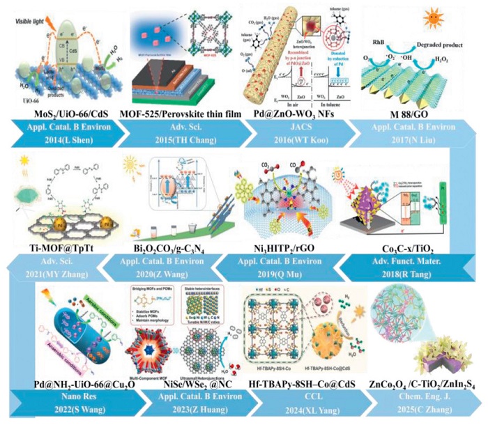
 DownLoad:
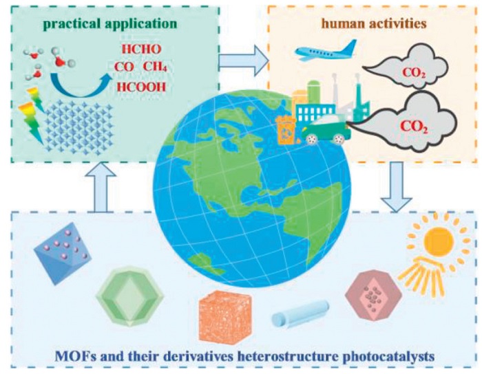
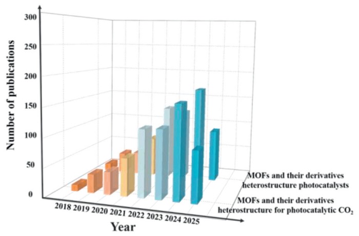
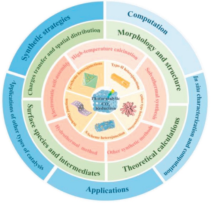
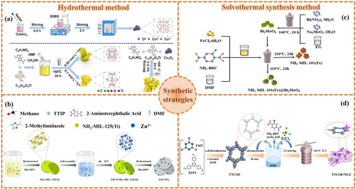
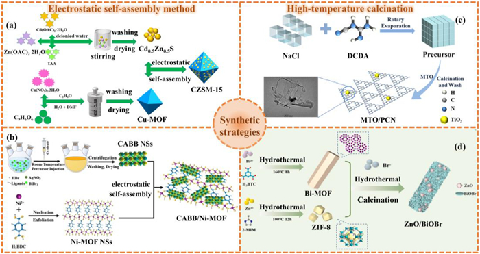
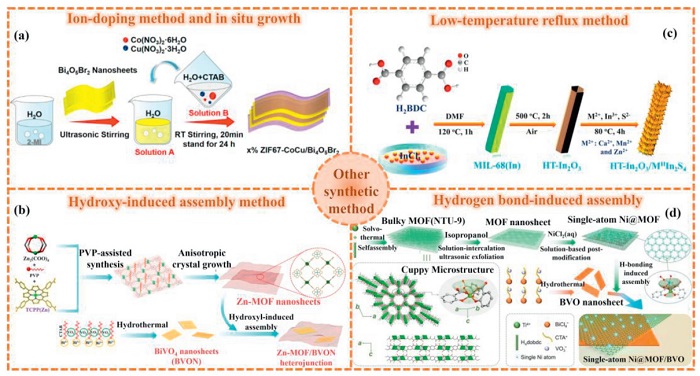
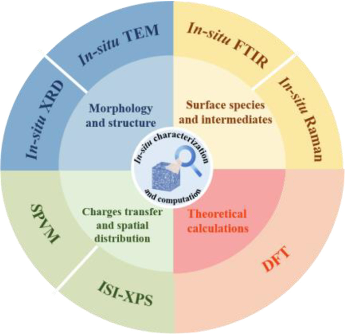
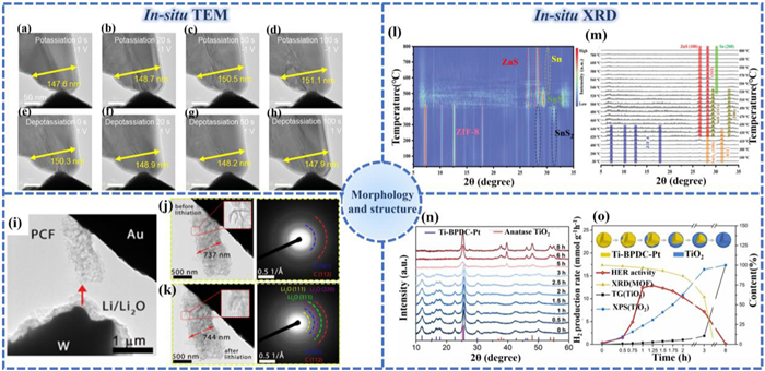
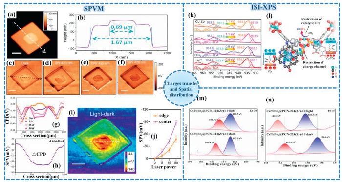
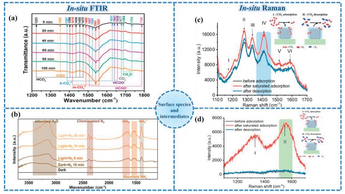
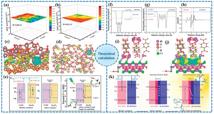
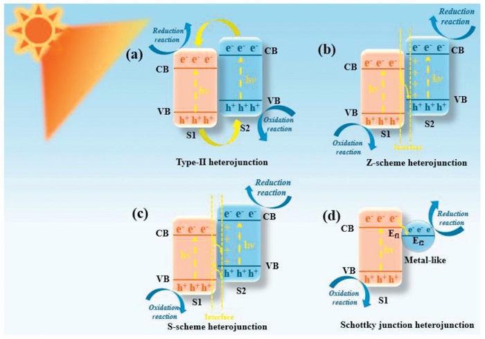
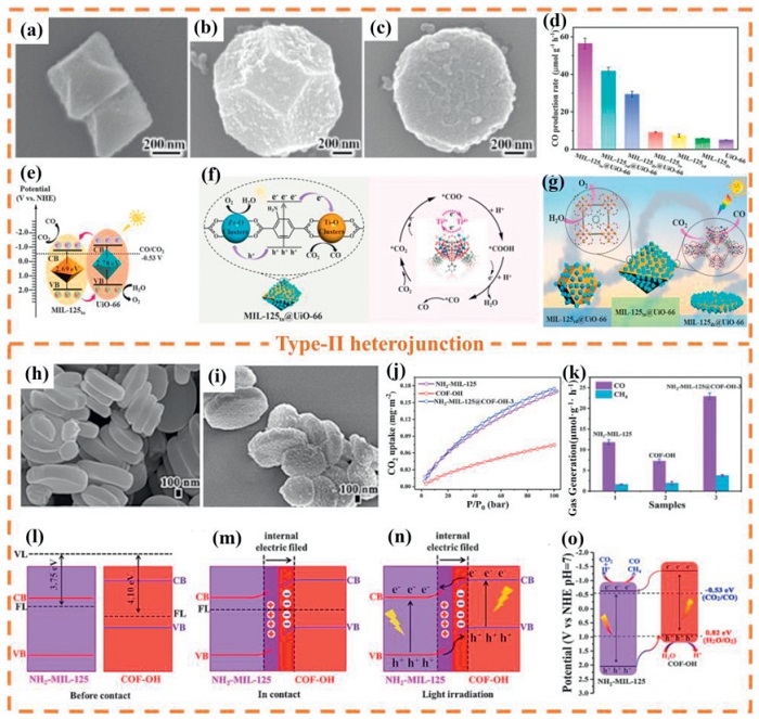
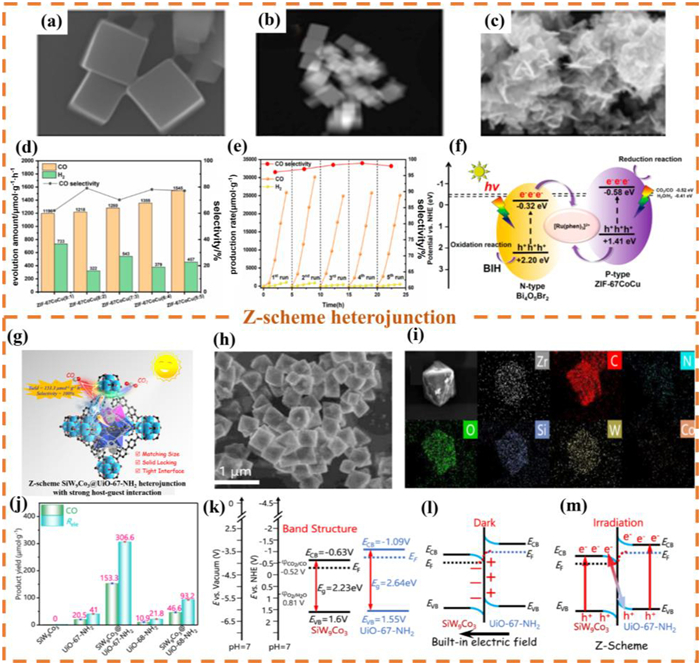
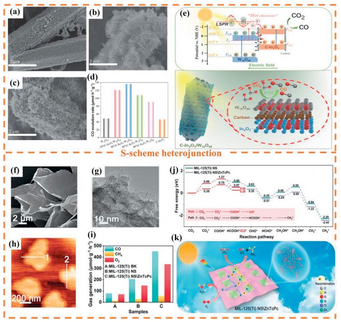
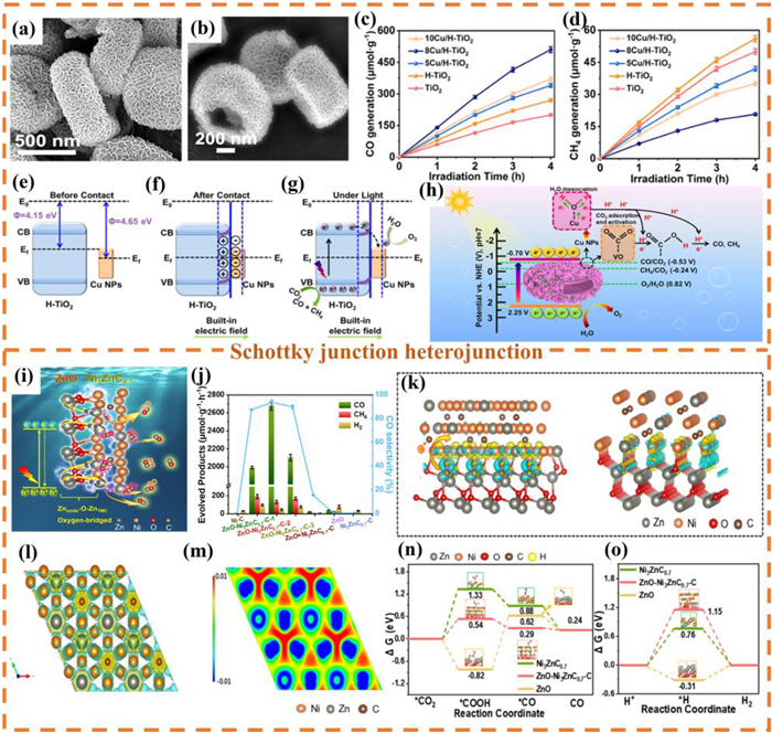
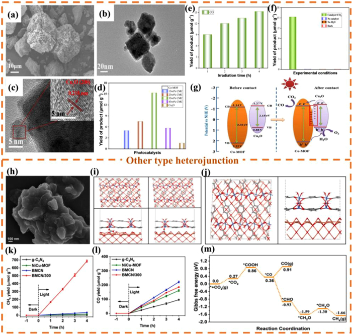
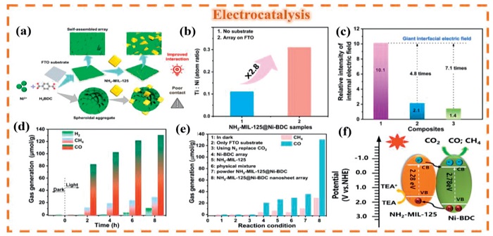
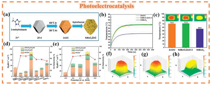
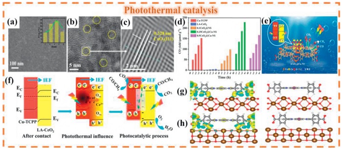
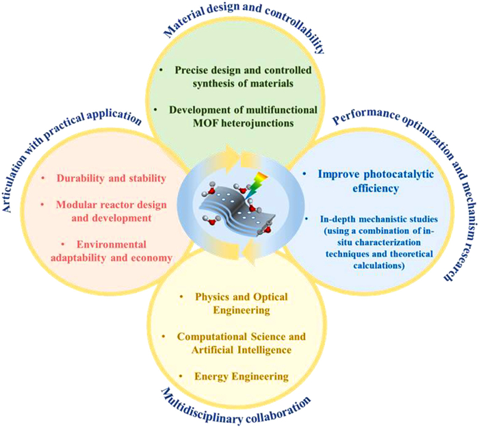

 下载:
下载:


 下载:
下载:
