School of Integrated Circuits, Huazhong University of Science and Technology, Wuhan 430074, China
b.
Key Laboratory of Materials Physics, Institute of Solid State Physics, Hefei Institutes of Physical Science, Chinese Academy of Sciences, Hefei 230031, China
duangt@hust.edu.cn (G. Duan). 1 These authors contributed equally to this work.
Received Date:
06 February 2025 Accepted Date:
24 July 2025 Revised Date:
15 July 2025 Available Online:
15 April 2026
Abstract:
The integration of advanced sensing materials as channel layers in devices is essential for constructing field-effect transistor (FET) biosensors. In this study, we synthesized high-crystallinity bimetallic M3(hexaaminotriphenylene)2 (M = Co, Ni) thin films as FET channel materials via an in-situ growth method using a mixed solvent system of water and N,N-dimethylformamide (DMF). This bimetallic metal-organic framework (MOF)-based FET then served as a glucose biosensor, achieving a high sensitivity and an ultra-wide detection range from 10 nmol/L to 10 mmol/L. Further studies reveal that the success of in-situ growth of the high-crystalline bimetallic MOF film can be attributed to the coordination solvent exchange reaction between the metal atomic center, DMF, and water. Furthermore, the introduction of bimetallic centers enhances the number of active sites within the MOF, thereby achieving an ultra-low detection limit and an ultra-wide detection range. This work presents a versatile approach for constructing high performance FET biosensors.
Blood sugar, as one of the most common physiological indicators for assessing physical health status, is receiving increasing attention [1-6]. Achieving wide-range, high-precision real-time detection of glucose levels in blood presents a critical challenge for the next generation of medical diagnostic equipment [7-14]. At present, the mainstream schemes for detecting glucose include electrochemical [15,16], optical [17-20] and field-effect transistor biosensors [21-26]. Among them, the electrolyte-gated FET is considered the most potential candidate for rapid on-site detection equipment, which is attributed to its special structure that employs the electric double layer as the dielectric layer and its compatibility with the semiconductor integration process.
The selection of the channel material is crucial for electrolyte-gated FET biosensors, as the potential changes induced by specific reactions in the solution directly influence the carrier distribution within the channel and, consequently, the sensing performance. In general, two fundamental physical and chemical properties are essential to ensure that the channel material is suitable for use in an effective biosensor [27-29]. Firstly, the material needs to possess abundant functional groups and a high density of catalytic active sites. This ensures that biological probe molecules are effectively anchored to the material, thereby enhancing the sensor's response. Secondly, this type of material must be effectively integrated onto the device substrate as a large-area thin film to ensure the high performance of the subsequent FET.
Currently, metal-organic framework (MOF) materials [30,31] are extensively utilized in the domain of biological detection on account of their abundant functional groups and multiple active catalytic sites [32-34]. Gao et al. synthesized Ni-MOF incorporating multiple catalytic active sites by utilizing 2-aminopyrazine ligands, thereby achieving efficient synergistic catalytic hydrolysis of acetylthiocholine chloride [35]. Sun et al. synthesized a trimetallic MOF based on Cu, Fe, and Zn metal centers. The catalytic activity of the trimetallic MOF was significantly enhanced in comparison with that of the monometallic MOF, enabling high-precision detection of acetylcholinesterase [36]. The multi-metal centers and multiple catalytic active sites constitute the advantages of MOF materials. However, the in-situ growth of such materials on device substrates poses significant challenges, which severely limits the further integration and performance enhancement of FET biosensors.
To achieve high-quality growth of MOF materials, it is essential to comprehensively consider the extranuclear electron configurations of both ligands and metal centers. Ni3(hexaaminotriphenylene)2 is a special MOF based on the 2,3,6,7,10,11-hexaaminotriphenylene·6HCl (HITP) ligand [37-39] and Ni2+ metal atom center. Studies have indicated that the empty antibonding dx2−y2 orbital of Ni2+ enables it to form a perfect square-planar coordination with the HITP ligand, rendering Ni3(hexaaminotriphenylene)2 with high crystallinity and the capability to grow well on the device substrates. However, the doping of other elements (such as Co, Cu, Fe) will severely diminish its crystallinity, thereby obscuring the advantage of multiple catalytic active sites introduced by the bimetallic center [40-45]. How to obtain highly active bimetallic materials and how to integrate MOF materials onto FET constitute an urgent issue that demands resolution.
Herein, high-crystallinity Co/Ni-HITP thin film was grown in-situ at the solid-liquid interface by a simple water-bath heating method. The use of N,N-dimethylformamide (DMF) regulates the coordination reaction between the metal center and the organic ligand and effectively enhances the crystallinity of MOF. Meanwhile, it can be observed that electron transfer occurs between the bimetallic center and the ligand. High-crystallinity Co/Ni-HITP thin film-based transistor is used to detect glucose, and the results show that this biosensor has good detection performances. The preparation of Co/Ni-MOF-based transistor biosensors demonstrates a universal method for producing high-quality new sensing material thin films, and also demonstrates its enormous potential in the field of biomedical devices.
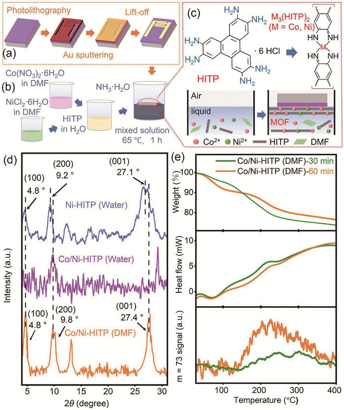
As is shown in Fig. 1a, after magnetron sputtering Au onto the developed substrate, lift-off was performed to obtain a substrate with 41 nm-thick electrodes (Fig. S1 in Supporting information). Fig. S2 (Supporting information) shows the size parameters of the relevant devices. Next, the plasma-treated substrate is inverted and immersed in the solution, allowing in-situ preparation of MOF thin films on the surface through a one-step water-bath heating method (Fig. 1b). Detailed parameters are described in the experimental methods section of Supporting information.
Figure 1
Figure 1.
(a) Schematic diagram of synthesis process for device substrate. (b) Schematic diagram for the synthesis of bimetallic MOF material using water/DMF mixed solvents. (c) Molecular structural formulas of HITP and M3(HITP)2 and schematic diagram of microscale synthesis process of M3(HITP)2. (d) XRD patterns of Ni-HITP and Co/Ni-HITP synthesized in aqueous solvent and Co/Ni-HITP synthesized in mixed solvent. (e) TGA-MS results of Co/Ni-HITP prepared with reaction time of 30 and 60 min.
Fig. 1c illustrates the microscopic synthesis mechanism of Co/Ni-HITP. In the solution, metal ions coordinate with the HITP ligand to form Co/Ni-HITP. During this reaction, DMF competes with the HITP ligand for coordination with metal ions, effectively slowing down the nucleation of MOFs and enhancing crystallinity, thereby enabling high-quality growth of MOF films on the substrate surface [46]. The XRD patterns and SEM images of Co-HITP synthesized in DMF solvent differ significantly from those of Co-MOF prepared in water, reflecting the influence of DMF solvent on material synthesis (Fig. S3 in Supporting information) [47,48].
To further demonstrate the role of DMF in MOF film synthesis, we prepared Ni-HITP (water) and Co/Ni-HITP (water) in aqueous solutions, as well as Co/Ni-HITP (DMF) in a DMF/water mixed solvent, and tested their XRD patterns (Fig. 1d). By comparing Ni-HITP (water) (blue curve) with Co/Ni-HITP (water) (purple curve), it is observed that the characteristic XRD peaks at approximately 4.8° and 27.1° disappear, indicating the introduction of Co metal centers significantly reduces MOF crystallinity. Due to the last unpaired electron of the 3d7 orbital of Co2+, Co3HITP2 has a distorted quadrilateral configuration [49]. The purple curve exhibits substantial noise and the characteristic XRD peaks disappear, indicating a significant decrease in crystallinity of the material. As for Co/Ni-HITP (DMF) (orange-yellow curve), its characteristic XRD peaks have a slight shift relative to those of Ni-MOF (blue curve) possibly due to Co2+-induced lattice distortions. The FWHM values of Ni-HITP at 4.8°, 9.2°, and 27.1° are 0.86°, 0.88°, and 1.8°, respectively, while those of Co/Ni-HITP are 0.76°, 1.02°, and 1.2°, respectively [50]. This indicates that MOF synthesis in DMF significantly enhances crystallinity.
As shown in Fig. 1e, TGA tests were conducted on samples with different reaction times (the upper two panels). Compared with the sample with a longer reaction time (60 min), the sample with a shorter reaction time (30 min) exhibits an earlier temperature range of mass loss. This is attributed to difference desorption temperature ranges caused by variations in the adsorption capacities of water and DMF in samples with different reaction times. Simultaneously, the desorption signals of DMF molecules were monitored during heating through MS test (the bottom panel). The 60-min sample demonstrated significantly stronger DMF desorption signals than the 30-min sample. Both the results demonstrate that DMF participates in the reaction process.
The SEM images of the Co/Ni-HITP films prepared under the two schemes show that Co/Ni-HITP (DMF) exhibits the morphology of nanosheet stacked together, which further indicates the improvement of MOFs crystallization (Figs. 2a–c); Co/Ni-HITP (water) has an amorphous state/phase (Fig. 2d). The synthesis of Co-MOF films exhibits similar outcomes to that of bimetallic MOF (Fig. S3 in Supporting information). When DMF is employed as the reaction solvent, an increased abundance of nanosheets is observed within the material's microstructure, leading to the formation of a thin film on the device surface. The TEM images shown in Figs. 2e and f reveal that the Co/Ni-HITP has a nano-sheet structure. Fig. 2g and Fig. S4 (Supporting information) show the AFM analysis of Co/Ni-HITP film. The thickness of the uniformly grown sheet-like bottom film is about 49.25 nm, and the overall film roughness is about 331 nm (Fig. 2h). The difference in the height of the nanoflower clusters may be the main reason of the high roughness of the film.
Figure 2
Figure 2.
(a–c) SEM images of Co/Ni-HITP (DMF) membrane. (d) SEM images of Co/Ni-HITP (water) membrane. (e) TEM image. (f) HRTEM image (the inset is the selected area diffraction pattern). (g) AFM image and (h) the height test result of Co/Ni-HITP (DMF) film.
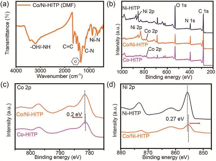
Fig. 3a presents the FT-IR results of Co/Ni-HITP (DMF). The peak at 3433 cm-1 corresponds to the amino groups on the benzene rings, and the peak at 603 cm-1 represents the Ni-N bonds. The electronic structure of the material was further investigated through XPS.
Figure 3
Figure 3.
(a) FT-IR spectra of Co/Ni-HITP (DMF). (b) XPS spectra of Co/Ni-HITP, Co-HITP and Ni-HITP. (c) High resolution Co 2p XPS spectra of Co/Ni-HITP and Co-HITP. (d) High resolution Ni 2p XPS spectra of Co/Ni-HITP and Ni-HITP.
Fig. 3b reveals that Co/Ni-HITP, Co-HITP and Ni-HITP all have the same binding energy peaks at 532.42, 399.01 and 284.94 eV, which are corresponding to O 1s, N 1s and C 1s respectively. In the XPS spectrum of Co/Ni-HITP, the peaks of Co 2p and Ni 2p respectively locate at 781.36 and 855.33 eV, indicating that both Co ion and Ni ion are involved in the coordination reaction, thus resulting in a bimetallic Co/Ni-HITP. The XPS spectra of Co 2p (Fig. 3c) show that the binding energy of Co 2p in Co/Ni-HITP increases by 0.20 eV compared with that of Co-HITP. However, in the spectra of Ni 2p (Fig. 3d), the binding energy of Ni 2p in Co/Ni-HITP decreases by 0.27 eV than that of Ni-HITP. The shifts of the binding energy of Co 2p and Ni 2p in bimetallic MOFs reveal the electron transfer between Co ion and Ni ion through the aromatic ring structure of HITP ligand, thus leading to the coupling effect between them. Moreover, because the ability of Ni to capture electrons is stronger than that of Co, the overall electron cloud density in Co/Ni-HITP is transferred towards Ni, which therefore increases the binding energy of Co 2p along with the decreased binding energy of Ni 2p.
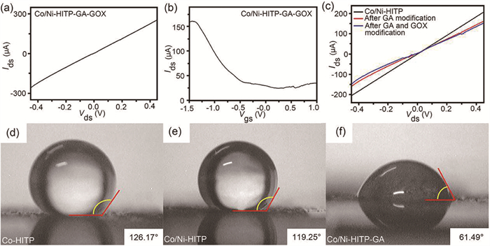
After in-situ growth of Co/Ni-HITP film by water-bath heating method and fabrication of Co/Ni-HITP-FET device, glutaraldehyde (GA) and glucose oxidase (GOX) were further modified on the surface of Co/Ni-HITP-FET, which was named as Co/Ni-HITP-GA-GOX-FET. The electrical properties tests of the Co/Ni-HITP-GA-GOX-FET are shown in Fig. 4. The good linear relationship of the I-V curves indicates a good ohmic contact between the Co/Ni-HITP channel material and the gold electrode (Fig. 4a). The liquid gate transfer curve of the sensor indicates that the drain current (Ids) increased with the increase of the negative gate voltage (Fig. 4b), which shows a typical p-type characteristic of FET. Moreover, Fig. 4c shows the I-V curves of Co/Ni-HITP film after modifying glutaraldehyde and glucose oxidase sequentially. After the modification of GA, the slope of the I-V curve of the sensor decreases, indicating that the resistance of the channel material increased. After the modification of GOX, the slope of the I-V curve further decreases, and the resistance of the channel material increases further. The modification of GA and GOX leads to the transfer of electrons to the MOF film, leading to the decrease of hole carriers in the channel material, which eventually decrease the conductance of the MOF channel material. The change of I-V curves also indicated the successful modification of GA and GOX on the MOF film.
Figure 4
Figure 4.
(a) I-V curves of Co/Ni-HITP-GA-GOX-FET. (b) Transfer curves of Co/Ni-HITP-GA-GOX-FET sensor. (c) I-V curves for Co/Ni-HITP without modification, after GA modification, and after modification of GA and GOX. Contact angle of (d) Co-HITP membrane, (e) Co/Ni-HITP membrane and (f) Co/Ni-HITP membrane after modifying with glutaraldehyde.
Figs. 4d–f show the contact angle tests of Co-HITP films, Co/Ni-HITP film and Co/Ni-HITP film modified with GA. The introduction of Ni atom improves the hydrophilic characteristics of MOF to some extent, which is also related to the growth of the film (Figs. 4d and e). The improvement of hydrophilicity of bimetallic Co/Ni-HITP can be attributed to the improvement of roughness of Co/Ni-HITP film due to the nanoflower clusters grown on the surface. Furthermore, the significant decrease of contact angle of Co/Ni-HITP (61.49°, Fig. 4f) after modification with GA is mainly due to the introduction of aldehyde group, which improves the hydrophilicity of the film.
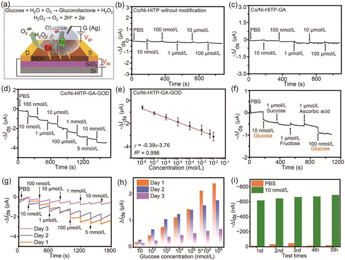
Fig. 5 shows the glucose sensing performance of Co/Ni-HITP-GA-GOX-FET sensor. The detection principle of Co/Ni-HITP-GA-GOX-FET sensor for glucose is based on the enzymatic decomposition reaction by glucose oxidase (GOX), which causes the change of the conductance of the channel material (Fig. 5a). As shown in Fig. 5a, when glucose solution is added, glucose is decomposed by glucose oxidase (GOX) to generate gluconolactone and H2O2, and then H2O2, is further decomposed to generate O2, hydrogen ions (H+) and electrons (e-). The specific reaction formula as follows (Eqs. 1 and 2):
Glucose+H2O+O2→Gluconolactone+H2O2
(1)
H2O2→O2+2H++2e−
(2)
Figure 5
Figure 5.
(a) Schematic illustration of detection principle of Co/Ni-HITP-GA-GOX-FET sensor. Glucose sensing performance of (b) Co/Ni-HITP-FET sensor, (c) Co/Ni-HITP-GA-FET sensor and (d) Co/Ni-HITP-GA-GOX-FET sensor. (e) Relationship curve between the current response and glucose concentration. (f) Selectivity test with nontarget analytes (sucrose, fructose, ascorbic acid, 1 µmol/L) and target analytes (glucose, 10 and 100 nmol/L). (g) Long-term stability test of Co/Ni-HITP-GA-GOX-FET sensor. (h) Comparison of current variation values in Co/Ni-HITP-GA-GOX-FET sensor for gradient-concentration glucose detection at the 1st, 2nd and 3rd day. (i) Stability test of Co/Ni-HITP-GA-GOX-FET sensor for 10 nmol/L glucose.
As the enzymatic reaction proceeds, electrons accumulate continuously on the surface of the channel material. For this p-type Co/Ni-HITP-GA-GOX-FET sensor, holes are main carriers, and the generation of electrons will correspondingly reduce the concentration of hole carriers, thus decreasing the conductivity of Co/Ni-HITP channel material, which is equivalent to the n-type doping effect for FET device. Therefore, the drain current of the sensor has a corresponding downward trend, and the detection of glucose is realized by detecting the change of the drain current.
The current response is defined as -ΔIds = -(I - I0), where I is the current after the addition of different concentration glucose and I0 is the current for pure PBS solution at the beginning of test. PBS solution was added as blank sample to get I0. As comparative test, Figs. 5b and c show the response to glucose of the Co/Ni-HITP-FET sensor without any modification and the Co/Ni-HITP-GA-FET sensor modified only with GA. Results show that two sensors have not a significant current response to glucose without modification of glucose oxidase, which indicates that glucose oxidase plays a key role in the identification of glucose. Then, when glucose solutions with concentrations ranging from 10 nmol/L to 10 mmol/L was added, respectively, the sensor immediately showed a significant current change. And there was a significant current response to each concentration of glucose. As the concentration increased to 10 mmol/L, the current response (-ΔIds) of the sensor compared to the PBS basal current was about 3.30 µA, indicating a sensitive response of the sensor to glucose (Fig. 5d).
By calculating and fitting the current response of the sensor to each concentration of glucose, the relationship between the current response and the glucose concentration was shown in Fig. 5e. The response of the sensor to glucose exhibits a linear relationship in the concentration range of 10 nmol/L ~ 5 mmol/L. The fitted linear relationship is as follows: y = −0.39x – 3.76, and the linear correlation coefficient (R2) is 0.996.
In order to compare the difference in glucose detection performance between the bimetallic MOF-based sensor and monometallic sensor, Ni-HITP-GA-GOX-FET sensor and Co-HITP-GA-GOX-FET sensor were fabricated by the same modification method. Fig. S5a (Supporting information) illustrates the detection performance of the Ni-HITP-GA-GOX-FET sensor. It is observed that while the detected current exhibits significant fluctuations, these changes do not follow a linear trend. Fig. S5b (Supporting information) reveals that the Co-HITP-GA-GOX-FET sensor also has a similar current response for glucose. But the total current response of sensor is about 1.23 µA from 10 nmol/L to 10 mmol/L, which is much smaller than the current response of bimetallic MOF-based sensor. Besides, the Co-MOF-based sensor tends to saturate at lower concentrations. Furthermore, Fig. S5c (Supporting information) illustrates the detection outcomes of the water-phase bimetallic MOF-based sensor. It is evident that the sensor exhibits satisfactory linearity in detecting changes in current; however, the absolute value of the overall current change remains relatively small. This phenomenon may be attributed to the suboptimal growth quality of the film in the aqueous phase.
Fig. 5f is the selectivity test of Co/Ni-HITP-GA-GOX-FET sensor for glucose and nontarget analytes, where fructose, sucrose and ascorbic acid was used as interferences. One can see that after adding 10 nmol/L glucose, the sensor has an obvious current change. Then, after adding 1 µmol/L fructose, sucrose and ascorbic acid, respectively, the current response of sensor had only a weak response. Finally, after adding 100 nmol/L glucose again, the drain current changed significantly again. Above results reveal the sensor exhibits a highly selective response to various types of sugars. For assessing the long-term stability of Co/Ni-HITP-GA-GOX-FET sensors, multiple sensors were fabricated under identical conditions. These sensors were uniformly modified following the methodology outlined in the manuscript, stored at 0–4 ℃, and tested at 24-h intervals. Fig. 5g illustrates the test results of the sensors over three consecutive days. Fig. 5h exhibits comparison of current variation values in Co/Ni-HITP-GA-GOX-FET sensor for gradient-concentration glucose detection on the 1st, 2nd and 3rd day. The results indicate that the linearity and variation amplitude are optimal on the 1st day, both the values show a slight decrease on the 2nd day, and there is a significant performance decline on the 3rd day. This may be due to the loss of activity of the GOX on the sensor's surface. These findings indicate that the sensor maintains high sensitivity for up to two days post-modification.
The stability test results are shown in Fig. 5i. It can be seen that the sensor exhibits a response value of about 600 nA to 10 nmol/L glucose. Meanwhile, the current changes in the five tests are the similar, which reflects the stability of the sensor. To further investigate the reusability of the sensor, we conducted repeated tests on the same sensor at two-day intervals. These tests were performed without any modifications to the sensor between trials. Results shown in Figs. S6a–c (Supporting information) indicate that the current response of the sensor on the second day decreased slightly compared with that on the zeroth day, while the current decrease on the fourth day was significantly high. The current responses of the three tests compared on 0th, 2nd, and 4th day were 2.89, 2.78, and 1.53 µA, respectively, which was decreased by 3.81% on 2nd and 47.10% on 4th day. The reason for the decrease of current response may be the inactivation of the glucose oxidase modified on the surface of the MOF film after long-term storage and the loss of active enzyme caused by multiple washings before and after the test. Therefore, the Co/Ni-HITP-GA-GOX-FET sensor is mainly considered for one-time detection presently.
To better evaluate the glucose sensor performance, a comparison of detection ability between Co/Ni-HITP biosensor and previously reported glucose sensors were summarized in Table S1 (Supporting information). One can see that MOF materials using HITP as ligands exhibit superior performance. The Co/Ni bimetallic MOF prepared in this work achieves the lowest detection limit (10 nmol/L) and widest detection range, with a sensitivity of 39 µA (mol/L)-1 mm-2. Furthermore, the excellent linear detection ability of these highly crystalline MOFs with multi-metallic catalytic centers highlights their significant application potential.
In summary, we used a simple water-bath heating method to in-situ grow a high-quality conductive bimetallic Co/Ni-MOF thin film at the solid-liquid interface. Moreover, DMF was used as the organic solvent to modulate the coordination reaction between the metal center and the organic ligand. The Co/Ni-HITP-GA-GOX-FET biosensor was prepared by further modifying the GA and GOX on the surface of the Co/Ni-HITP film for glucose detection. The synergistic effect between the Co center and the Ni center makes the glucose sensor based on the bimetallic MOF have better detection performance, which can realize the sensitive and specific detection of glucose in the range of 10 nmol/L ~ 10 mmol/L. A novel method for fabricating high-crystallinity and high-quality thin films using a mixed solvent system of DMF and water has been developed. This approach significantly enhances the application potential of advanced sensing materials, enabling superior catalytic activity and high-sensitivity biosensing.
Declaration of competing interest
The authors declare that they have no known competing financial interests or personal relationships that could have appeared to influence the work reported in this paper.
The authors acknowledge the support from the National Key R&D Program of China (No. 2020YFB2008701). The authors are grateful for Analytical & Testing Center of Huazhong University of Science and Technology (HUST) for the support in structure and morphology characterization. The authors also thank engineer Guangxue Zhang and engineer Haili Zhang in Wuhan National Laboratory for Optoelectronics of HUST for the support in device fabrication, too.
Supplementary materials
Supplementary material associated with this article can be found, in the online version, at doi:10.1016/j.cclet.2025.111636.
[1]
J. Hippisley-Cox, C. Coupland, BMJ 352 (2016) i1450. doi: 10.1136/bmj.i1450
[2]
M. Brownlee, Nature 414 (2001) 813–820. doi: 10.1038/414813a
[3]
S. Wild, G. Roglic, A. Green, et al., Diabetes Care 27 (2004) 1047–1053. doi: 10.2337/diacare.27.5.1047
[4]
American Diabetes Association, Diabetes Care 37 (2014) S81–S90. doi: 10.2337/dc14-S081
Y. Wu, M.I. Breeze, G.J. Clarkson, et al., Angew. Chem. Int. Ed. 55 (2016) 4992–4996. doi: 10.1002/anie.201600896
[47]
D. Sheberla, L. Sun, M.A. Blood-Forsythe, et al., J. Am. Chem. Soc. 136 (2014) 8859–8862. doi: 10.1021/ja502765n
[48]
D. Sheberla, J.C. Bachman, J.S. Elias, et al., Nat. Mater. 16 (2017) 220–224. doi: 10.1038/nmat4766
[49]
Y. Lian, W. Yang, C. Zhang, et al., Angew. Chem. Int. Ed. 59 (2020) 286–294. doi: 10.1002/anie.201910879
[50]
G. Wu, J. Huang, Y. Zang, et al., J. Am. Chem. Soc. 139 (2017) 1360–1363. doi: 10.1021/jacs.6b08511
Figure 1
(a) Schematic diagram of synthesis process for device substrate. (b) Schematic diagram for the synthesis of bimetallic MOF material using water/DMF mixed solvents. (c) Molecular structural formulas of HITP and M3(HITP)2 and schematic diagram of microscale synthesis process of M3(HITP)2. (d) XRD patterns of Ni-HITP and Co/Ni-HITP synthesized in aqueous solvent and Co/Ni-HITP synthesized in mixed solvent. (e) TGA-MS results of Co/Ni-HITP prepared with reaction time of 30 and 60 min.
Figure 2
(a–c) SEM images of Co/Ni-HITP (DMF) membrane. (d) SEM images of Co/Ni-HITP (water) membrane. (e) TEM image. (f) HRTEM image (the inset is the selected area diffraction pattern). (g) AFM image and (h) the height test result of Co/Ni-HITP (DMF) film.
Figure 3
(a) FT-IR spectra of Co/Ni-HITP (DMF). (b) XPS spectra of Co/Ni-HITP, Co-HITP and Ni-HITP. (c) High resolution Co 2p XPS spectra of Co/Ni-HITP and Co-HITP. (d) High resolution Ni 2p XPS spectra of Co/Ni-HITP and Ni-HITP.
Figure 4
(a) I-V curves of Co/Ni-HITP-GA-GOX-FET. (b) Transfer curves of Co/Ni-HITP-GA-GOX-FET sensor. (c) I-V curves for Co/Ni-HITP without modification, after GA modification, and after modification of GA and GOX. Contact angle of (d) Co-HITP membrane, (e) Co/Ni-HITP membrane and (f) Co/Ni-HITP membrane after modifying with glutaraldehyde.
Figure 5
(a) Schematic illustration of detection principle of Co/Ni-HITP-GA-GOX-FET sensor. Glucose sensing performance of (b) Co/Ni-HITP-FET sensor, (c) Co/Ni-HITP-GA-FET sensor and (d) Co/Ni-HITP-GA-GOX-FET sensor. (e) Relationship curve between the current response and glucose concentration. (f) Selectivity test with nontarget analytes (sucrose, fructose, ascorbic acid, 1 µmol/L) and target analytes (glucose, 10 and 100 nmol/L). (g) Long-term stability test of Co/Ni-HITP-GA-GOX-FET sensor. (h) Comparison of current variation values in Co/Ni-HITP-GA-GOX-FET sensor for gradient-concentration glucose detection at the 1st, 2nd and 3rd day. (i) Stability test of Co/Ni-HITP-GA-GOX-FET sensor for 10 nmol/L glucose.

 DownLoad:


 下载:
下载:


 下载:
下载:
