Figure 1.
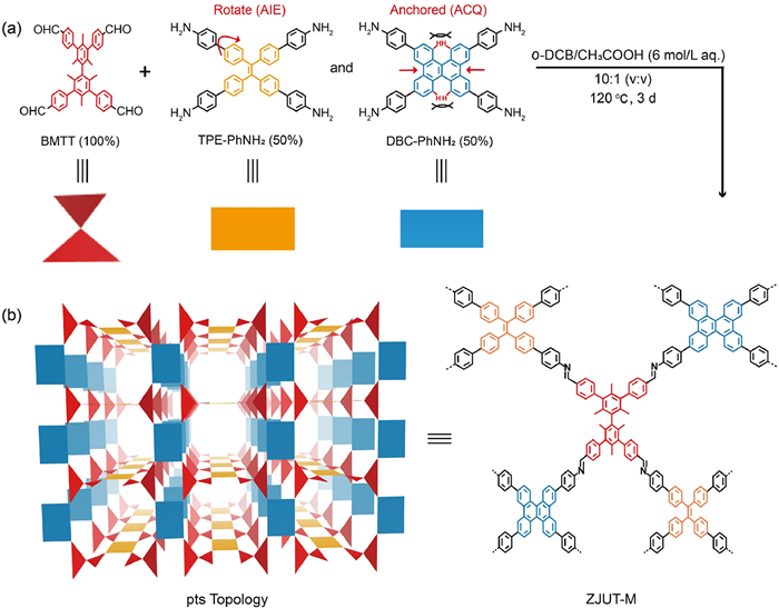
(a) Synthetic route and structural representation of ZJUT-M constructed from BMTT, TPE-PhNH2 and DBC-PhNH2. (b) Simulated pts topology for ZJUT-M.
Fluorophore integration strategy endowing 3D covalent organic frameworks with dual-mode white light emission
Jialiang Liu , Chengtao Gong , Jinchen Qian , Sen Wang , Yi Liang , Chenglong Guo , Yongwu Peng , Jun Pan

Fluorescent covalent organic frameworks (COFs), constructed from luminescent building blocks, hold significant promise for diverse applications, including chemical detection [1-6], biosensing [7-9], imaging [10,11] and white light-emitting diodes (WLEDs) [12-19]. While significant progress has been made in constructing two-dimensional (2D) fluorescent COFs through interlayer stacking modulation or morphology control [20,21], their fluorescence performance often suffers from π–π stacking-induced quenching, limiting their practical utility.
In contrast, three-dimensional (3D) fluorescent COFs offer a compelling alternative to mitigate fluorescence quenching [4,5,12,22,23]. Wang et al. reported a 3D COF (3D-TPE-COF) incorporating tetraphenylethylene units that exhibits yellow fluorescence in the solid state, driven by aggregation-induced emission (AIE) [12]. Wei et al. further expanded the field by synthesizing a dynamic 3D COF (dynaCOF) capable of suppressing aggregation-caused quenching (ACQ) via solvent adsorption, displaying tunable fluorescence colors [4]. However, achieving dual-mode fluorescence in 3D COFs remains a formidable challenge. This requires the integration of fluorophores with distinct emissive properties, necessitating precise control over molecular conformations and reactive sites to preserve framework order and crystallinity. Such design considerations are essential to maintain the intrinsic luminescent properties within the 3D conjugated framework.
Here, we address the challenge of achieving dual-mode fluorescence in COFs by employing a fluorophore integration strategy. A novel 3D COF (ZJUT-M) was designed and synthesized by incorporating two distinct fluorescent nodes, TPE-PhNH2, a high-degree-of-freedom chromophore with AIE properties, and DBC-PhNH2, a conformationally locked molecule that suppresses ACQ. Despite sharing identical molecular geometries, these nodes exhibit contrasting emission behaviors due to differences in the rotational freedom of their benzene rings (Fig. 1). ZJUT-M demonstrates dual-mode fluorescence, emitting yellow-green light in the solid state with a photoluminescence quantum yield of 11%, while in solution, it exhibits solvent-polarity-dependent fluorescence with PLQYs up to 35%. The emission properties are governed by the AIE effect of TPE-PhNH2 nodes in the solid state and the ACQ-suppressing capability of the conformationally locked DBC-PhNH2 nodes in solution. When applied to white-light-emitting diodes (WLEDs), ZJUT-M produced bright white light with CIE coordinates near pure white, whether dispersed in liquid or integrated with commercial blue LED lamps.
Two fluorescent nodes with 4-connected D2h symmetry were synthesized to achieve dual-mode luminescence. TPE-PhNH2, a monomer featuring AIE properties, and DBC-PhNH2, a conformationally locked molecule engineered to suppress ACQ, were employed as building blocks. These nodes were assembled with a T4-symmetric building unit in a 1:1 molar ratio to construct a multicomponent COF, designated as ZJUT-M. The synthesis was performed under solvothermal conditions using o-DCB and 6.0 mol/L acetic acid at 120 ℃ over three days, yielding a yellow solid powder with a yield of 85.1% (Section S2.2 in Supporting information for detailed procedures). Fourier transform infrared (FT-IR) spectrum of ZJUT-M displays a characteristic C=N stretching vibration peak at 1625 cm-1, alongside the disappearance of N—H stretching vibrations from the precursor nodes (TPE-PhNH2: 3374 and 3210 cm-1; DBC-PhNH2: 3356 and 3220 cm-1) and a reduction in the C=O stretching peak near 1700 cm-1, confirming the successful formation of imine linkages (Fig. S1 in Supporting information). Furthermore, solid-state 13C cross-polarization/magic angle spinning (CP/MAS) NMR spectrum exhibits a peak at 158 ppm, corresponding to imine carbon signals (Fig. S2 in Supporting information). Thermogravimetric analysis (TGA) reveals excellent thermal stability, with no significant weight loss observed up to 450 ℃ (Fig. S3 in Supporting information).
Microscopic characterization revealed a rough spherical morphology with homogeneous topography, as shown in scanning electron microscopy (SEM) images (Fig. S4 in Supporting information). Transmission electron microscopy (TEM) further confirmed the crystalline structure through visible lattice fringes (Fig. S5 in Supporting information). Powder X-ray diffraction (PXRD) analysis revealed sharp diffraction peaks at low angles, indicative of high crystallinity (Fig. 2a).
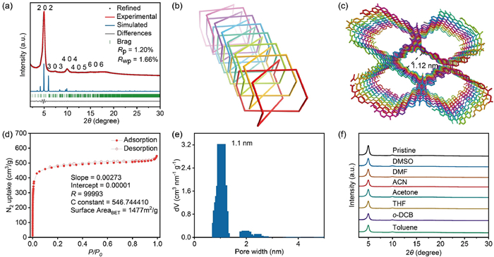
Based on the symmetry of the building blocks, the formation of a pts topological network with 7-fold interpenetration was proposed and validated. Major diffraction peaks were observed at 4.9°, 7.3°, 9.9°, 11.5°, and 14.8°, corresponding to the 202, 303, 404, 405, and 606 reflection planes, respectively (Fig. 2a). The simulated PXRD patterns from this model closely matched the experimental data (Figs. 2b and c, Figs. S6 and S7 in Supporting information). Pawley refinement of the experimental PXRD data provided unit cell parameters for ZJUT-M (a = 48.0272 Å, b = 5.1716 Å, c = 49.2921 Å, α = γnull= 90°, and β = 82.4006°, space group is P2/c) with negligible Rwp and Rp values of 1.66% and 1.20%, respectively (Table S1 in Supporting information).
The porosity of ZJUT-M was evaluated through N2 adsorption-desorption measurements at 77 K, yielding a Brunauer-Emmett-Teller (BET) surface area of approximately 1477 m2/g and a pore size distribution centered at 1.02 nm (Figs. 2d and e), highlighting its high porosity. Furthermore, ZJUT-M demonstrated exceptional chemical stability, retaining its crystallinity and structural integrity after 24 h of exposure to a variety of solvents, including o-DCB, toluene, acetone, acetonitrile (ACN), tetrahydrofuran (THF), dimethylformamide (DMF), and dimethyl sulfoxide (DMSO) (Fig. 2f and Fig. S8 in Supporting information).
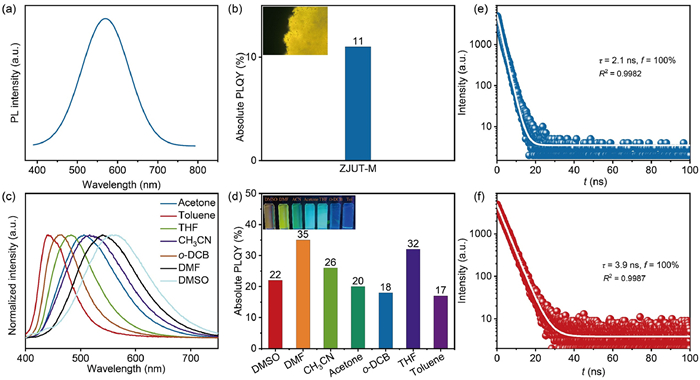
Following the successful synthesis of this highly crystalline 3D COF incorporating AIE and ACQ emission properties, its optical characteristics were systematically examined. Under 365 nm UV light, solid-state ZJUT-M emitted yellow fluorescence at 571 nm with a quantum yield of 11% (Figs. 3a and b). When dispersed in various solvents, ZJUT-M exhibited solvent-dependent fluorescence, with emission wavelengths ranging from 441 nm in toluene to 557 nm in DMSO, transitioning from blue to yellow (Fig. 3c). This red shift in emission is attributed to the dipole interactions between ZJUT-M and the surrounding solvent [24,25]. Notably, the highest photoluminescence quantum yield of 35% was observed in DMF, where ZJUT-M emitted bright yellow light at 523 nm (Fig. 3d). The dual-mode fluorescence emission of ZJUT-M in both solid and solution states was confirmed by photoluminescence (PL) decay measurements. ZJUT-M powders and its DMF solution exhibited mono-exponential decay behavior, with average lifetimes of 2.1 and 3.9 ns, respectively (Figs. 3e and f). These nanosecond-level lifetimes underscore the potential of ZJUT-M for applications in display and lighting technologies.
To elucidate the luminescence mechanism underlying the dual-mode fluorescence behavior of ZJUT-M, we hypothesized that its contrasting emission properties stem from the distinct contributions of the TPE-PhNH2 and DBC-PhNH2 fluorescent nodes. To validate this hypothesis, two isoreticular 3D COFs, ZJUT-F (constructed exclusively with TPE-PhNH2) and ZJUT-R (constructed exclusively with DBC-PhNH2), were synthesized and characterized (Figs. S9-S20, Tables S2 and S3 in Supporting information).
PXRD analysis revealed that all three COFs share a pts topology with 7-fold interpenetration, confirming structural similarity. Photoluminescence (PL) studies showed that ZJUT-F exhibited yellow emission at 570 nm with a quantum yield of 19% under 365 nm excitation. In contrast, ZJUT-R demonstrated negligible emission in the solid state (PLQY, 0.7%) (Figs. S21-S23 in Supporting information). When dispersed in solvents, ZJUT-F displayed minimal fluorescence (Figs. S24 and S25 in Supporting information), whereas ZJUT-R exhibited strong solvent-dependent emission, with wavelengths at 439, 451, 474, 495, 501, 523, and 540 nm in toluene, o-DCB, THF, acetone, ACN, DMF, and DMSO, respectively (Fig. S26 in Supporting information). The emission peaks of ZJUT-R align closely with those observed for ZJUT-M in solution (Fig. S27 in Supporting information). A comparative photoluminescence analysis in DMF revealed a sequential decrease in fluorescence intensity among the three COFs, ranked as ZJUT-R > ZJUT-M > ZJUT-F, with PLQYs of 51%, 35%, and 2.7%, respectively. Time-resolved PL decay measurements showed mono-exponential behavior for ZJUT-F powder and ZJUT-R in DMF, with average lifetimes of 2.3 and 4.2 ns, respectively (Figs. S28 and S29 in Supporting information). In contrast, ZJUT-F in DMF showed biexponential decay characteristics, similar to the behavior of ZJUT-R powder (Figs. S30 and S31 in Supporting information). These findings corroborate our hypothesis that the solvent-dependent luminescence of ZJUT-M originates from the DBC-PhNH2, while its solid-state fluorescence is attributed to TPE-PhNH2. ZJUT-R, incorporating the rigid DBC-PhNH2 fluorescent nodes, exhibits weak solid-state fluorescence due to restricted rotational freedom and suppressed ACQ effect [26], while maintaining strong solvent-stabilized emission with minimal non-radiative energy loss. In contrast, ZJUT-F, containing the flexible TPE-PhNH2 fluorescent nodes, demonstrates prominent solid-state fluorescence driven by AIE effect [27-32], but its solution-phase fluorescence is significantly quenched by non-radiative decay mechanisms associated with rotational freedom of the TPE-PhNH2 moieties.
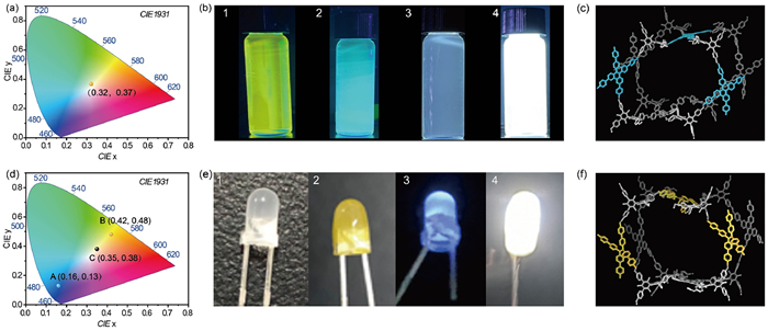
Recently, white light-emitting diodes (WLEDs) have garnered significant attention for their wide-ranging applications in display and lighting systems. Here, a suspension of ZJUT-M in a mixture of DMF and THF was prepared, yielding a unique system that emits bright white light under 365 nm UV irradiation. The CIE coordinates were determined as (0.322, 0.367) (Figs. 4a and b), with the luminescence primarily originating from DBC-PhNH2 units within ZJUT-M (Fig. 4c). Furthermore, ZJUT-M was applied as a luminescent film via a straightforward coating process onto a commercial blue LED lamp (emission peak ~450 nm). Upon activation, the modified LED produced bright white light with CIE coordinates of (0.295, 0.323) (Figs. 4d and e), closely matching the ideal coordinates for pure white light (0.33, 0.33). In this configuration, the luminescence is primarily derived from TPE-PhNH2 units in ZJUT-M (Fig. 4f). These results underscore the versatility of ZJUT-M in WLED applications, whether utilized as a solid-state material or in suspension.
In summary, we present the design and synthesis of a novel 3D covalent organic framework (COF) exhibiting dual-mode fluorescence in both solid and solution states. This achievement leverages a fluorophore integration strategy to combine fluorescent nodes with distinct emission properties. The resulting COF demonstrates significant potential for applications in white-light-emitting diodes (WLEDs), functioning effectively as a solid-state material or in suspension. This work establishes an efficient approach for tailoring COFs with multi-state fluorescence, expanding the application horizon of fluorescent COF materials for advanced lighting and display technologies.
The authors declare that they have no known competing financial interests or personal relationships that could have appeared to influence the work reported in this paper.
Jialiang Liu: Writing – original draft, Formal analysis, Data curation. Chengtao Gong: Writing – original draft, Validation, Methodology, Funding acquisition, Formal analysis. Jinchen Qian: Writing – review & editing, Visualization, Validation, Data curation. Sen Wang: Validation, Methodology. Yi Liang: Visualization, Validation. Chenglong Guo: Validation, Formal analysis. Yongwu Peng: Writing – review & editing, Supervision, Project administration, Investigation, Conceptualization. Jun Pan: Writing – review & editing, Project administration, Investigation, Funding acquisition, Conceptualization.
This work was supported by the National Natural Science Foundation of China (Nos. 22375179, 52172160, 22105202, 22275185, 223B2117), and the Fundamental Research Funds for the Provincial Universities of Zhejiang (No. RF-C2022005).
Supplementary material associated with this article can be found, in the online version, at doi:
C. Yuan, S.G. Fu, K.W. Yang, et al., J. Am. Chem. Soc. 143 (2021) 369–381. doi: 10.1021/jacs.0c11050
Y. Peng, Y. Huang, Y.H. Zhu, et al., J. Am. Chem. Soc. 139 (2017) 8698–8704. doi: 10.1021/jacs.7b04096
W.R. Cui, C.R. Zhang, W. Jiang, et al., Nat. Commun. 11 (2020) 436. doi: 10.1038/s41467-020-14289-x
L. Wei, T. Sun, Z.L. Shi, et al., Nat. Commun. 13 (2022) 7936. doi: 10.1038/s41467-022-35674-8
Y.P. Cheng, J.J. Xin, L.B. Xiao, et al., J. Am. Chem. Soc. 145 (2023) 18737–18741. doi: 10.1021/jacs.3c06159
A. Jrad, G. Das, N. Alkhatib, et al., Nat. Commun. 15 (2024) 10490. doi: 10.1038/s41467-024-53945-4
A. Mal, R.K. Mishra, V.K. Praveen, et al., Angew. Chem. Int. Ed. 57 (2018) 8443–8447. doi: 10.1002/anie.201801352
J.M. Wang, B. Yan, Anal. Chem. 91 (2019) 13183–13190. doi: 10.1021/acs.analchem.9b03534
D. Liang, X.Y. Zhang, Y. Wang, et al., Bioact. Mater. 14 (2022) 145–151.
J.Y. Zeng, X.S. Wang, B.R. Xie, et al., Angew. Chem. Int. Ed. 59 (2020) 10087–10094. doi: 10.1002/anie.201912594
S. Kang, H. Ahn, C. Park, et al., Adv. Sci. 10 (2023) 2300462. doi: 10.1002/advs.202300462
H.M. Ding, J. Li, G.H. Xie, et al., Nat. Commun. 9 (2018) 5234. doi: 10.1038/s41467-018-07670-4
S. Haldar, D. Chakraborty, B. Roy, et al., J. Am. Chem. Soc. 140 (2018) 13367–13374. doi: 10.1021/jacs.8b08312
X. Li, Q. Gao, J.F. Wang, et al., Nat. Commun. 9 (2018) 2335. doi: 10.1038/s41467-018-04769-6
C. Krishnaraj, A.M. Kaczmarek, H.S. Jena, et al., ACS Appl. Mater. Interfaces 11 (2019) 27343–27352. doi: 10.1021/acsami.9b07779
T. Ishi-i, H. Tanaka, I.S. Park, et al., Chem. Commun. 56 (2020) 4051–4054. doi: 10.1039/D0CC00251H
S. Kundu, B. Sk, P. Pallavi, et al., Chem. Eur. J. 26 (2020) 5557–5582. doi: 10.1002/chem.201904626
V. Anand, R. Mishra, Y. Barot, Dyes Pigments 191 (2021) 109390. doi: 10.1016/j.dyepig.2021.109390
X.H. Li, H.J. Tang, L. Gao, et al., Polymer 241 (2022) 124474. doi: 10.1016/j.polymer.2021.124474
S. Wan, J. Guo, J. Kim, et al., Angew. Chem. Int. Ed. 47 (2008) 8826–8830. doi: 10.1002/anie.200803826
G. Das, B.P. Biswal, S. Kandambeth, et al., Chem. Sci. 6 (2015) 3931–3939. doi: 10.1039/C5SC00512D
S.Y. Ding, M. Dong, Y.W. Wang, et al., J. Am. Chem. Soc. 138 (2016) 3031–3037. doi: 10.1021/jacs.5b10754
C. Gao, J. Li, S. Lin, J.L. Sun, C. Wang, J. Am. Chem. Soc. 142 (2020) 3718–3723. doi: 10.1021/jacs.9b13824
Q. Gao, X. Li, G.H. Ning, et al., Chem. Commun. 54 (2018) 2349–2352. doi: 10.1039/C7CC09866A
B. Gui, J.J. Xin, Y.P. Cheng, et al., J. Am. Chem. Soc. 145 (2023) 11276–11281. doi: 10.1021/jacs.3c01729
H. Wang, C.T. Gong, P. Jin, et al., Chem. Commun. 58 (2022) 9798–9801. doi: 10.1039/D2CC03498K
Y.N. Hong, J.W. Lam, B.Z. Tang, Chem. Soc. Rev. 40 (2011) 5361–5388. doi: 10.1039/c1cs15113d
W.J. Gan, Z.H. Zhang, X.H. Zheng, et al., Asian J. Org. Chem. 12 (2023) e202200559. doi: 10.1002/ajoc.202200559
L. Liao, Z.R. Zhang, X.Y. Guan, et al., Chin. J. Chem. 40 (2022) 2081–2088. doi: 10.1002/cjoc.202200194
L. Zhang, F. Guo, S. Xu, et al., Adv. Mater. 37 (2025) 2304620. doi: 10.1002/adma.202304620
J. Fang, Z.Y. Fu, X.H. Chen, et al., Angew. Chem. Int. Ed. 62 (2023) e202304234. doi: 10.1002/anie.202304234
M.J. Yuan, F.Y. Ma, L.X. Chen, et al., J. Am. Chem. Soc. 146 (2024) 1250–1256. doi: 10.1021/jacs.3c10511

Figure 1 (a) Synthetic route and structural representation of ZJUT-M constructed from BMTT, TPE-PhNH2 and DBC-PhNH2. (b) Simulated pts topology for ZJUT-M.

Figure 2 (a) Experimental, Pawley refined, and simulated PXRD patterns of ZJUT-M. (b) Schematic depiction of the 7-fold interpenetrated pts topology. (c) Porous architecture of ZJUT-M. (d) N2 adsorption-desorption isotherms of ZJUT-M measured at 77 K. (e) Pore size distributions of ZJUT-M calculated from adsorption data. (f) PXRD patterns of ZJUT-M after immersion in various solvents for 24 h, demonstrating structural stability.

Figure 3 (a) Photoluminescence spectra of ZJUT-M in powder form. (b) Absolute PLQY of ZJUT-M powder (inset: photograph of ZJUT-M powder under UV irradiation). (c) Photoluminescence spectra of ZJUT-M dispersed in various solvents. (d) Absolute PLQYs of ZJUT-M in different solvents (inset: photographs of ZJUT-M dispersions under UV irradiation). (e) PL decay curve of ZJUT-M powder (blue) with mono-exponential fitting (white). (f) PL decay curve of ZJUT-M in DMF (red) with mono-exponential fitting (white).

Figure 4 (a) CIE 1931 chromaticity diagram illustrating the white-light emission of ZJUT-M in solution with coordinates of 0.32, 0.37. (b) Photographs of ZJUT-M dispersions in DMF (1), THF (2), a mixed solvent (THF: DMF = 1:1, v/v) (3), and the mixed solvent under 365 nm UV irradiation (4). (c) Solution-phase luminescence attributed to conformationally restricted fluorophores that suppress ACQ effect. (d) CIE chromaticity diagram highlighting emission coordinates of the blue LED (A: 0.16, 0.13), ZJUT-M in the solid state (B: 0.42, 0.48), and the COF-coated LED (C: 0.35, 0.38) under 450 nm excitation. (e) Photographs of LEDs: an unlit reference blue LED (1), an unlit ZJUT-M-coated LED (2), a lit reference blue LED emitting blue light (3), and a lit ZJUT-M-coated LED emitting white light (4). (f) Solid-state luminescence arising from flexible fluorophores, inducing AIE effect in the solid state.

 扫一扫看文章

扫一扫关注我们
 DownLoad:
 下载:
下载:
 下载:
下载: