Received Date:
26 November 2024 Accepted Date:
25 June 2025 Revised Date:
25 June 2025 Available Online:
15 August 2026
Abstract:
To mitigate the slow conversion kinetics and "shuttle effect" of polysulfides, a flexible, self-supporting Ni-nitrilotriacetic acid coordination polymer nanowires/few layer Ti3C2Tx MXene (Ni-NTA/f-Ti3C2Tx) interlayers with three-dimensional network is elaborately devised and fabricated. In this framework, the M–O–M (M = metal ion) linkages on polymer nanowires present superior catalytic activity towards the conversion of lithium polysulfides (LiPSs). Meanwhile, physical blocking and chemical trapping of LiPSs are also achieved, owing to the hierarchical porous structure and polar surface of hybrid interlayer. As a result, the lithium sulfur batteries assembled with Ni-NTA/f-Ti3C2Tx exhibit a high specific capacity of 899.5 mAh/g at 1 C and 529.6 mAh/g can be kept after 500 cycles with a decay rate of 0.08% per cycle, confirming the efficient alleviation of shuttle effect.
The increasing demand for electric vehicles and portable electronic devices has significantly contributed to the development of high energy density rechargeable batteries [1,2]. Lithium-sulfur batteries (LSBs) have garnered substantial attention in recent years due to their low cost, high energy density, and high theoretical specific capacity [3–5]. However, certain inherent drawbacks of sulfur cathodes, such as low electrochemical conductivity, large volume change during cycling, particularly the detrimental "shuttle effect" of lithium polysulfides (LiPSs), impede the practical application of LSBs [6–8].
To address these issues, several strategies including sulfur cathode design, separator modification, and electrolyte optimization have been developed [9]. Among these approaches, the incorporation of interlayers has emerged as a straightforward and effective method. On the one hand, the interlayer can serve as a physical barrier to impede polysulfides diffusion. On the other hand, the functional interlayer can provide chemical bonding and even catalytic sites for the adsorption and conversion of sulfur and LiPSs in LSBs [10–14]. For example, Yang et al. [15] reported a TiO2/TiN heterostructure modified N-doped carbon foam interlayer, which could provide the three-dimensional (3D) flexible conductive network to balance the surface adsorption and redox conversion of LiPSs. However, the facile construction of interlayers with low cost and high performance is still insufficient in research [16]. Besides metal and its inorganic compounds, coordination polymers (CPs) especially the porous type, i.e., metal organic frameworks (MOFs) have attracted increasing attention owing to their abundant availability, lightweight nature, diverse molecular structures, and well-defined functional groups [17–19]. Their particular M–O (M = metal ion) linkages play an important role in constructing active catalytic sites [20]. However, the low conductivity always hinders their electrochemical performances [20–22]. To resolve the obstacle, materials with high conductivity are always introduced [23,24]. For example, Wang et al. [25] prepared a multifunctional Li-S interlayer consisting of Zr-based MOF and carbon nanotubes (CNTs). The incorporation of CNTs effectively enhances the electron and ion transport of composites, while also facilitating sufficient exposure of active sites in Zr-MOF for capturing and catalyzing LiPSs. Different from the nonpolar carbon materials, the two-dimensional (2D) transition metal carbides and nitrides (MXenes) exhibit not only high electronic conductivity but remarkable polar surfaces towards LiPSs [26,27]. Nevertheless, the layer restacking together with oxidative degradation significantly impedes their applications [28]. Thus, the combination of stable and dispersed CPs with conductive MXenes seems a promising method to solve the above problems.
Herein, a flexible self-supporting membrane was synthesized with one-dimensional (1D) nickel coordinated nitrilotriacetic acid (Ni-NTA) polymer nanowires (NWs) as reinforcement and 2D few-layer Ti-based MXene (f-Ti3C2Tx) as matrix through a facile self-assembly method. The catalytic ability of the M–O–M linkage of Ni-NTA could be activated by the addition of conductive MXene nanosheets (≈20 wt%). Simultaneously, the restacking of MXene nanosheets was effectively inhibited by the 1D NWs. The optimized Ni-NTA/f-Ti3C2Tx networks were employed as multifunctional layers with physical, chemical and catalytic abilities toward the dissolved LiPSs. Thus, the as-assembled LSBs exhibit excellent electrochemical performances including large specific capacity, high-rate capabilities (481.6 mAh/g at 2 C) and stable cycling performance with a low capacity decay rate of 0.08% per cycle at 1 C.
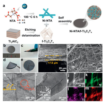
Fig. 1a illustrates the preparation of Ni-NTA/f-Ti3C2Tx self-supporting membranes. Ni-NTA NWs synthesized by the hydrothermal method exhibit a significantly high aspect ratio and facilitate to exposure of enormous active sites (Fig. S1a in Supporting information). Additionally, MXene nanosheets were obtained through the typical acid etching and exfoliation way as reported (Fig. S1b in Supporting information) [29]. During the following sonication and vacuum-filtration processes, MXene nanosheets with a negative charge spontaneously adhere to the exposed surface of positively charged Ni-NTA NWs via electrostatic attraction and van der Waals forces, thereby accomplishing the self-assembly process [30]. The digital image shown in Fig. 1b displays freestanding Ni-NTA/f-Ti3C2Tx membranes with a smooth surface devoid of wrinkles and cracks, proving the uniform distribution of different components. Various mechanical deformations were evaluated for the Ni-NTA/f-Ti3C2Tx membranes (Figs. 1c-e), demonstrating their superior flexibility and mechanical properties. Scanning electron microscope (SEM) analysis was conducted to examine the morphology of the Ni-NTA/f-Ti3C2Tx membranes (Figs. 1f and g). Fig. 1f presents a cross-sectional image, revealing that the membrane has a thickness of ≈17.6 µm. Notably, it can be observed that the 2D MXene exhibits a uniform distribution within the network structure, acting as an adhesive to intricately intertwine the 1D Ni-NTA NWs, thereby forming a highly interconnected and integrated 3D flexible conductive composite network (Fig. 1g). Transmission electron microscopy (TEM) image (Fig. 1h) further confirms the high aspect ratio of Ni-NTA with an average diameter of ≈500 nm and the large lateral size of MXene. Moreover, the high-resolution TEM image (Fig. 1i) clearly shows the (002) lattice fringe of MXene with a spacing of 1.35 nm coated on the surface of Ni-NTA, confirming the tight interaction of MXene with Ni-NTA. Such unique interface structure constructs stable transmission pathways, significantly enhancing the efficient electron and ion conduction in the whole interlayer, and facilitating the M–O–M linkages in Ni-NTA for redox transformations. Scanning transmission electron microscopy (STEM, Fig. 1j) and elemental mapping analysis (Figs. 1k-m) indicate a homogeneous distribution of the Ni, Ti, and C elements and the formation of firm composite structures.
Figure 1
Figure 1.
(a) Schematic illustration for the construction of Ni-NTA/f-Ti3C2Tx self-supporting interlayer. (b-e) Digital images present the flexibility (rolling, folding) of the obtained Ni-NTA/f-Ti3C2Tx self-supporting membranes. (f) Cross-section and (g) top view SEM images of the membrane. (h) TEM, (i) HRTEM, (j) STEM, and (k-m) elemental (Ni, Ti, C) mapping images of the interlayer.
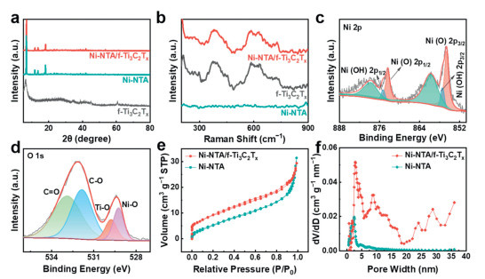
X-ray diffraction (XRD) patterns and Raman spectra were performed to investigate the crystal and chemical structures of the obtained Ni-NTA/f-Ti3C2Tx membrane. As depicted in Fig. 2a, the (002) characteristic peak of Ti3C2Tx MXene confirms its layered structure with an average interlayer distance of ≈1.38 nm. Sharp peaks are observed for the prepared Ni-NTA NWs indicating their excellent crystallinity. The Ni-NTA/f-Ti3C2Tx exhibits consistent diffraction peaks with those of Ni-NTA as it takes a major mass proportion of ≈80 wt%. Furthermore, the (002) characteristic peak of Ti3C2Tx disappears after assembly, which is entirely overshadowed by the Ni-NTA peak. In contrast, the Raman spectrum of Ni-NTA/f-Ti3C2Tx reveals three distinct peaks at 209, 397, and 635 cm−1 in according with the single f-Ti3C2Tx as there are no characteristic peaks for Ni-NTA in a test range of 200−900 cm−1 (Fig. 2b). The first peak is assigned to the A1g model which is out-of-plane vibration of Ti, C atoms and surface groups (-F, -O) [31]. The latter two peaks represent Eg modes related to out-of-plane vibrations [31]. The complementary results of XRD patterns and Raman spectra further confirm the construction of stable composite interlayers.
Figure 2
Figure 2.
(a) XRD patterns and (b) Raman spectra of pure Ni-NTA, f-Ti3C2Tx, and Ni-NTA/f-Ti3C2Tx. XPS spectra of (c) Ni 2p, and (d) O 1s for Ni-NTA/f-Ti3C2Tx. (e) Nitrogen adsorption-desorption isotherms and (f) pore size distribution of Ni-NTA/f-Ti3C2Tx.
The X-ray photoelectron spectroscopy (XPS) was conducted to investigate the chemical bonding environment of various elements in the Ni-NTA/f-Ti3C2Tx sample. The survey spectrum (Fig. S2a in Supporting information) reveals the presence of Ni, Ti, C, N, and O elements. The Ni 2p spectrum exhibits four fitting peaks of Ni2+ along with two shakeup satellites. The peaks at 855.7 eV (2p3/2) and 873.4 eV (2p1/2) are attributed to the Ni–O band, while the peaks at 857.1 eV (2p3/2) and 874.9 eV (2p1/2) correspond to the Ni–OH band. (Fig. 2c) [32]. Meanwhile, the O 1s spectra can be fitted into four peaks (Fig. 2d): The presence of the Ni–O bond is further confirmed by the peak observed at 529.2 eV [33], and the peaks at higher binding energies correspond to C=O (532.9 eV), C–O (531.8 eV), and Ti–O (529.7 eV) bonds [26]. It is observed that the chemical bonding in the orbitals of Ti 2p produces an XPS characteristic peak at 455.8 eV and 457.3 eV, respectively (Fig. S2b in Supporting information). The Ti–C bond is derived from the MXene skeleton, and the presence of the TiO2 peak indicates a slight oxidation of the MXene nanosheets [34]. As shown in Fig. S2c (Supporting information), the C 1s spectra can be fitted into four types of carbon species: C–Ti (282.1 eV), C–C (284.8 eV), C–O (286.7 eV) and C=O (289.4 eV), confirming the existence of electronegative functional groups on MXene edges and surface.
In the investigation of separator materials, the abundant porous structure, and hierarchical pore size distribution play key roles in facilitating lithium ion diffusion and physically constraining of LiPSs. As confirmed by the N2 adsorption-desorption isotherm curves (Fig. 2e), the specific surface area of Ni-NTA/f-Ti3C2Tx exhibits a significant increase (32.8 m2/g) compared to that of single Ni-NTA nanowires (18.9 m2/g). The enhanced specific surface area is favorable for LiPSs adsorption, and provides more active sites for electrochemical reactions involving LiPSs [35]. Furthermore, the composite structure exhibits a wide pore size distribution ranging from 1 nm to 5 nm upon introducing MXene (Fig. 2f). The original microporous structure of Ni-NTA transforms into a hierarchical porous structure consisting of micropores and mesopores. Micropores facilitate electrolyte absorption, thereby improving separator wettability and enhancing lithium ion conductivity, whereas mesopores offer additional active sites for LiPSs capture and catalysis [36]. The resulting micro-mesoporous structure with a large specific surface area enables efficient permeation of lithium ions while exerting stronger physical constraints on LiPSs [37].
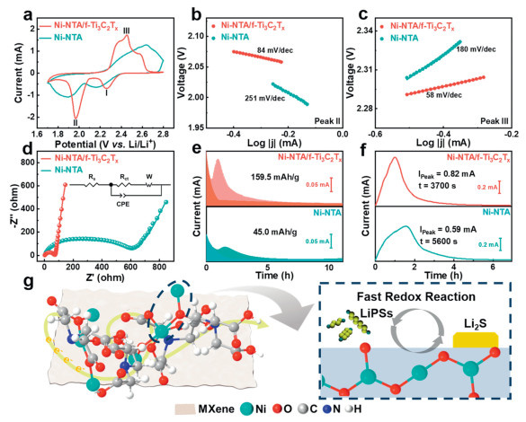
The ability of the Ni-NTA/f-Ti3C2Tx interlayer to block LiPSs is authenticated by Li2S6 permeate in experiments (Fig. S3 in Supporting information). The LiPSs pass through the Ni-NTA/PP and PP separator by displaying a distinct deep yellow colour on the other side of the device after 12 h, indicating poor LiPSs suppression. In contrast, no LiPSs are detected in the device with the Ni-NTA/f-Ti3C2Tx interlayer. The Ni-NTA/f-Ti3C2Tx interlayer effectively acts as a physical barrier, intercepting LiPSs and preventing their penetration. Fig. 3a and Fig. S4 (Supporting information) show the CV curves of LSBs with Ni-NTA/f-Ti3C2Tx/PP, Ni-NTA/PP, and PP as indicated in a voltage range of 1.7–2.8 V at a scan rate of 0.1 mV/s. All three electrodes exhibit typical redox peaks of LSBs, including two reduction peaks and one oxidation peak [38]. The cells with Ni-NTA display lower reduction potentials and higher oxidation potentials, indicating significant potential polarization due to hysteresis in the redox reaction, which ascribes to the low electrical conductivity of the CPs. In contrast, the Ni-NTA/f-Ti3C2Tx demonstrates enhanced electrochemical reaction kinetics and elevated electrochemical activity attributed to the construction of a 3D conductive network, as evidenced by CV curves showing the largest peak current and smallest potential polarization. To quantify the electrocatalytic effect, the Tafel slopes of the calculated oxidation peaks and reduction peaks are shown in Figs. 3b and c, Fig. S5 (Supporting information). Two cathodic peaks (Peak Ⅰ and Peak Ⅱ) correspond to the transformation from S8 to Li2Sn (6 ≤ n ≤ 8) and from Li2Sn (2 ≤ n ≤ 4) to Li2S, respectively. Additionally, the anode peak (peak Ⅲ) corresponds to the transformation from Li2S to S8. Evidently, Ni-NTA/f-Ti3C2Tx exhibits the lowest Tafel slope for both reduction and oxidation reactions, indicating that it can effectively facilitate the conversion between LiPSs and Li2S during these processes [39].
Figure 3
Figure 3.
(a) CV curves of Ni-NTA, and Ni-NTA/f-Ti3C2Tx cells at 0.1 mV/s. Tafel plots for the CV curves calculated from (b) the reduction peaks Ⅱ and (c) the oxidation peaks Ⅲ. (d) EIS and fitted files of Ni-NTA, and Ni-NTA/f-Ti3C2Tx cells. (e) Potentiostatic discharge curves at 2.05 V and (f) charge curves at 2.4 V for Ni-NTA, and Ni-NTA/f-Ti3C2Tx cells. (g) Coordination patterns of Ni-NTA/f-Ti3C2Tx molecule and schematic diagram for promoting the conversion of LiPSs to Li2S.
The resistive characteristics of cells with different interlayers are further investigated using electrochemical impedance spectra (EIS), which are fitted by the equivalent circuit in Fig. 3d and Table S1 (Supporting information). It can be observed that Ni-NTA/f-Ti3C2Tx/PP cell exhibits a significantly lower charge transfer resistance (Rct) (70.8 Ω) compared with Ni-NTA/PP cell (540.7 Ω). This improvement can be attributed to excellent conductivity provided by tightly coated MXene nanosheets on Ni-NTA, forming a highly conductive 3D network structure that facilitates electron transfer. The Warburg (Wo) value is associated with the mass transport impedance of ions from the bulk solution to the electrode-electrolyte interface and consists of three parameters: the Warburg resistance (Wo-R, Ω), the Warburg time constant (Wo-T, s), and the ideality factor (Wo-P) [40]. Low capacitance values observed in the fitted circuit indicate that Ni-NTA/f-Ti3C2Tx facilitates faster diffusion of lithium ions to match the reaction rate [41]. In contrast, without the incorporation of polar MXene nanosheets, poor electrical conductivity exhibited by Ni-NTA leads to an overall electrochemical performance hindered by a "short-board effect", thereby impeding rapid ion diffusion.
To investigate the conversion from soluble LiPSs to solid Li2S, potentiostatic discharge tests are conducted on different substrates (Fig. 3e). The precipitation capacities of Li2S are 159.5 mAh/g and 45.0 mAh/g for Ni-NTA/f-Ti3C2Tx and Ni-NTA cathodes, respectively. A larger precipitation capacity of the Ni-NTA/f-Ti3C2Tx cathode implies more rapid reaction kinetics between LiPSs and Li2S. Notably, constant potential charging experiments confirm that the Ni-NTA/f-Ti3C2Tx cathode exhibits the highest constant voltage current (0.82 mA) and the shortest response time (3700 s) for the Li2S dissolution peak, surpassing those observed with the Ni-NTA cathode (Fig. 3f). It is worth mentioning that pure MXene based interlayer don’t exhibit ideal catalytic performance in cells, potentially attributes to hindered exposure of functional surfaces and ion diffusion caused by the stacking arrangement of MXene nanosheets (Fig. S7 in Supporting information). The above points can be further supported by assembling symmetric cells. The CV curve obtained from the symmetric cell assembled with Ni-NTA/f-Ti3C2Tx exhibits a higher current peak compared to that of the Ni-NTA sample at a scan rate of 50 mV/s (Fig. S8 in Supporting information). The exceptional catalytic performance could be ascribed to the distinctive M–O–M coordination pattern in Ni-NTA, which forms a 3D transition metal oxide framework (Fig. 3g) [42–44]. Compared to conventional M–O linkages [45,46], the enhanced connectivity between metal ions results in synergistic effects that greatly accelerate LiPSs conversion and promote 3D deposition of Li2S.
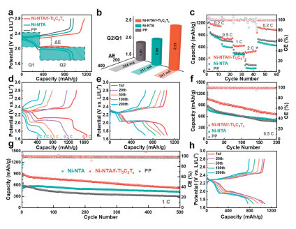
Fig. 4a illustrates the initial charge-discharge profiles of the LSBs with Ni-NTA/f-Ti3C2Tx interlayer at 0.2 C. The capacity contribution of the two discharge plateaus is denoted as Q1 and Q2, respectively, which are utilized to investigate the conversion level of sulfur species under different voltages. The high voltage plateau (Q1) is associated with the conversion of S8 to long-chain LiPSs, while the low voltage plateau (Q2) corresponds to the subsequent reduction of LiPSs into insoluble products [47]. Furthermore, the potential difference (ΔE) between charge and discharge plateaus is employed to comprehend the LiPSs transformation kinetics and polarization in LSBs. Fig. 4b demonstrates the corresponding ΔE values and Q2/Q1 ratio. In all tested samples, the cathode incorporating the Ni-NTA/f-Ti3C2Tx interlayer exhibits a significantly low ΔE value (241 mV), indicating minimal electrochemical polarization and rapid conversion kinetics. Moreover, the cathode with the Ni-NTA/f-Ti3C2Tx interlayer displays the highest Q2/Q1 ratio of 2.51, further verifying that the "shuttle effect" is greatly suppressed and loss of active material is effectively prevented by the incorporation of Ni-NTA/f-Ti3C2Tx interlayer [48].
Figure 4
Figure 4.
(a) Galvanostatic charge-discharge profiles of the LSBs with different interlayers at 0.2 C. (b) ΔE and Q2/Q1 values obtained from charging-discharging curves. (c) Rate performance of LSBs with different interlayers at various current densities. Galvanostatic charge-discharge profiles of the LSBs with Ni-NTA/f-Ti3C2Tx interlayer at (d) different current densities and (e) 0.5 C. Cycling performances of LSBs with different interlayer at (f) 0.5 C and (g) 1 C. (h) Galvanostatic charge-discharge profiles of the LSBs with Ni-NTA/f-Ti3C2Tx interlayer under a higher sulfur loading of 3.2 mg/cm2 at 0.2 C.
The rate performances of the assembled LSBs utilizing Ni-NTA/f-Ti3C2Tx, Ni-NTA, and f-Ti3C2Tx interlayers, along with a pure PP separator, are evaluated at different current densities (Fig. 4c and Fig. S9 in Supporting information). Among them, Ni-NTA/f-Ti3C2Tx shows the highest rate performance, delivering capacities of 1185.2–481.6 mAh/g at current densities of 0.2–2 C, which is higher than the cells with Ni-NTA (970.4–84.1 mAh/g), f-Ti3C2Tx (642.8–240.1 mAh/g) and PP (953.7–185.1 mAh/g). Furthermore, the capacity can be recovered to 1090.2 mAh/g when the rate is back to 0.2 C. Ni-NTA demonstrates the lowest rate performance due to the significant interface resistance between the interlayer and the electrode, which impedes efficient electron transfer. Furthermore, the galvanostatic charge-discharge (GCD) curves of LSBs at various rates are presented in Fig. 4d and Figs. S10a and b (Supporting information). The Ni-NTA/f-Ti3C2Tx exhibits the most stable discharge platform and smallest polarization at different current densities. This behavior could be attributed to the superior ability of Ni-NTA/f-Ti3C2Tx to catalyze the conversion of LiPSs and lower electrochemical resistance, which accelerates redox kinetics of LiPSs.
The corresponding cycling performance of cells with different interlayers at 0.5 C is further presented in Figs. 4e and f and Fig. S11 (Supporting information). After 200 cycles, the LSBs with Ni-NTA/f-Ti3C2Tx/PP, Ni-NTA/PP, f-Ti3C2Tx/PP, and PP demonstrate sustained reversible capacities of 657.7, 513.1, 407.6, and 471.8 mAh/g respectively. The LSBs are also tested at a high current rate of 1 C for an extended investigation into their long-term cyclability (Fig. 4g). The initial discharge capacity (899.5 mAh/g) of cells with Ni-NTA/f-Ti3C2Tx interlayer is significantly higher compared to those with Ni-NTA interlayer (569.4 mAh/g) or PP (650.4 mAh/g), indicating a superior utilization rate of sulfur. Impressively, even after undergoing 500 cycles at 1 C, LSBs equipped with the Ni-NTA/f-Ti3C2Tx interlayer exhibit a discharge capacity of 529.6 mAh/g and experience only minimal capacity loss of 0.08% per cycle, outperforming LSBs with Ni-NTA interlayer (423.2 mAh/g) or PP (304.3 mAh/g). Compared to other interlayers based on MXene or coordination polymers, the Ni-NTA/f-Ti3C2Tx interlayer also demonstrates excellent cycling stability (Table S2 in Supporting information). Note that, the cells with Ni-NTA interlayer experience a slight capacity increase during cycling, which could potentially be attributed to the gradual reactivation of initially inactive active sites. By considering the GCD curves (Figs. S12a-c in Supporting information), it is evident that the Ni-NTA/f-Ti3C2Tx displays the most stable voltage profile and the lowest polarization voltage during cycling. The cycling performance is further evaluated at current densities of 0.2 C (Figs. S13 and S14a-c in Supporting information). Remarkably, LSBs equipped with the Ni-NTA/f-Ti3C2Tx interlayer exhibit exceptional durability and perform excellently even under high sulfur loading (3.2 mg/cm2) (Fig. 4h and Fig. S15 in Supporting information). This further confirms that the prepared Ni-NTA/f-Ti3C2Tx interlayer could effectively adsorb LiPSs and accelerate their redox reaction kinetically. Furthermore, this research finding also has the potential for extension and application to other transition metal systems (Figs. S16a-d in Supporting information).
In summary, a novel 3D hybrid structure Ni-NTA/f-Ti3C2Tx, consisting of Ni-based NWs and MXene nanosheets was successfully synthesized through a facile self-assembly strategy and served as an efficient interlayer for high performance LSBs. The interconnected Ni-NTA/f-Ti3C2Tx flexible conductive network offered an abundant hierarchical porous structure with high electrical conductivity, which served as an efficient physical and chemical barrier to obstruct LiPSs. The electrical behavior test further confirmed that the M–O–M linkages in Ni-NTA NWs together with the conductive Ti3C2Tx nanosheets enabled the fast LiPSs conversion kinetics. By combining physical/chemical inhibition and catalytic conversion strategies, the LSBs with the Ni-NTA/f-Ti3C2Tx interlayer exhibited excellent electrochemical performance. What is more, this work provides valuable insights for designing and constructing coordination polymer based composite interlayers toward high performance LSBs.
Declaration of competing interest
The authors declare that they have no known competing financial interests or personal relationships that could have appeared to influence the work reported in this paper.
The authors acknowledge the financial support from National Natural Science Foundation of China (Nos. U22A20145, 52072151, 52171211, 52102253, 52271218), Jinan Independent Innovative Team (No. 2020GXRC015), Major Program of Shandong Province Natural Science Foundation (Nos. ZR2023ZD43, ZR2021ZD05), General Program of Shandong Province Natural Science Foundation (ZR2024ME200), Shandong Provincial Youth Innovation Team Development Plan of Colleges and Universities (No. 2022KJ100) and Science and Technology Program of University of Jinan (Nos. XKY2119, XKY2304).
Supplementary materials
Supplementary material associated with this article can be found, in the online version, at doi:10.1016/j.cclet.2025.111514.
[1]
R. Chu, T.T. Nguyen, H. Song, et al., Energy Storage Mater. 61 (2023) 102877. doi: 10.1016/j.ensm.2023.102877
Figure 1
(a) Schematic illustration for the construction of Ni-NTA/f-Ti3C2Tx self-supporting interlayer. (b-e) Digital images present the flexibility (rolling, folding) of the obtained Ni-NTA/f-Ti3C2Tx self-supporting membranes. (f) Cross-section and (g) top view SEM images of the membrane. (h) TEM, (i) HRTEM, (j) STEM, and (k-m) elemental (Ni, Ti, C) mapping images of the interlayer.
Figure 2
(a) XRD patterns and (b) Raman spectra of pure Ni-NTA, f-Ti3C2Tx, and Ni-NTA/f-Ti3C2Tx. XPS spectra of (c) Ni 2p, and (d) O 1s for Ni-NTA/f-Ti3C2Tx. (e) Nitrogen adsorption-desorption isotherms and (f) pore size distribution of Ni-NTA/f-Ti3C2Tx.
Figure 3
(a) CV curves of Ni-NTA, and Ni-NTA/f-Ti3C2Tx cells at 0.1 mV/s. Tafel plots for the CV curves calculated from (b) the reduction peaks Ⅱ and (c) the oxidation peaks Ⅲ. (d) EIS and fitted files of Ni-NTA, and Ni-NTA/f-Ti3C2Tx cells. (e) Potentiostatic discharge curves at 2.05 V and (f) charge curves at 2.4 V for Ni-NTA, and Ni-NTA/f-Ti3C2Tx cells. (g) Coordination patterns of Ni-NTA/f-Ti3C2Tx molecule and schematic diagram for promoting the conversion of LiPSs to Li2S.
Figure 4
(a) Galvanostatic charge-discharge profiles of the LSBs with different interlayers at 0.2 C. (b) ΔE and Q2/Q1 values obtained from charging-discharging curves. (c) Rate performance of LSBs with different interlayers at various current densities. Galvanostatic charge-discharge profiles of the LSBs with Ni-NTA/f-Ti3C2Tx interlayer at (d) different current densities and (e) 0.5 C. Cycling performances of LSBs with different interlayer at (f) 0.5 C and (g) 1 C. (h) Galvanostatic charge-discharge profiles of the LSBs with Ni-NTA/f-Ti3C2Tx interlayer under a higher sulfur loading of 3.2 mg/cm2 at 0.2 C.


 DownLoad:

 下载:
下载:


