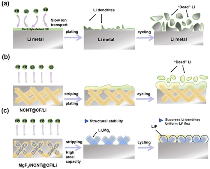
Figure 1.
Illustration of structure and Li plating behaviors of various substrates: (a) Bare Li, (b) NCNT@CF/Li, (c) MgF2/NCNT@CF-Li composite Li anode.

Stabilizing lithium metal anodes: Regulation nucleation-growth-passivation behavior with a multifunctional skeleton
Tianhui Li , Meizhen Qu , Gongchang Peng , Hanxiao Zhou , Zihao Su , Yi Chang , Bao Zhang , Wei Sun


Since the commercialization of Li-ion batteries (LIBs) in 1991, these batteries have undergone significant advancements as primary energy storage devices for portable electronics and electric vehicles [1]. However, more than the inherent energy density limitations of LIBs are needed to meet the increasing demands of grid-scale energy storage. To address this challenge, Li metal batteries, with their exceptionally high theoretical energy density, have emerged as potential candidates for current LIB technology. Despite being widely regarded as a promising anode material due to its lowest electrochemical potential (−3.04 V vs. standard hydrogen electrode) and high specific capacity (3860 mAh/g), Li metal faces significant challenges related to safety hazards and thermal runaway issues [2–5].
During the plating/stripping process, the non-uniform SEI exhibits heterogeneous Li-ion conductivity, which leads to inhomogeneous Li nucleation. Furthermore, the cycling of the Li metal anode makes the fragile SEI crack by the infinite volume expansion; the fresh Li metal is exposed, which possesses a lower energy barrier [6,7]. The increased ion flux at cracks accelerates the non-uniform Li deposition and Li dendrites growth, causing the failure of the Li metal anode (Fig. 1a). Recent research has addressed the critical challenge of stabilizing the electrolyte/electrode interphase. Approaches include regulating electrolyte composition [8–10], exploring additives [11–13], and fluorinating the solvents to form an in-situ SEI layer on the Li metal anode [14–16]. With the high shear modulus (55.2 Gpa), high interface energy (73.28 meV/A2), and good compatibility with Li metal, LiF has shown a potential to suppress Li dendrites and stabilize the electrode/electrolyte interphase [10,17]. Yet, in-situ LiF formation typically requires fluorinated solvents, which are costly and environmentally harmful. An alternative strategy to inhibit dendrite formation is to construct 3D structures, which provide a high specific surface area to reduce local current density during Li plating, such as carbon host [18–20], metal materials [4,21,22]. However, the positive effect of lithiophilic site is commonly tested under modest conditions (< 3 mAh/cm2). "Dead Li" accumulates on these sites, blocking the Li-ion diffusion channels under high areal capacity and making it hard to decrease the nucleation overpotential (Fig. 1b). Therefore, constructing an advanced functional composite electrode that achieves reversible Li electrodeposition/resolution and a dendrite-free morphology under high areal capacities is ideal yet remains challenging.
In this work, we proposed a skeleton-alloy-fluoride Li composite anode based on the above discussions. As depicted in Fig. 1c, the MgF2/NCNT@CF-Li anode realizes a reversible Li plating/stripping process by optimizing Li nucleation and growth and passivating the electrode/electrolyte interphase. The NCNT@CF matrix, with numerous lithiophilic sites, such as pyridine and pyrrole, promotes Li nucleation uniformly and suppresses huge volume variations. The homogeneous Li-Mg alloy maintains structural integrity upon lithiation at high areal capacities. The LiF-rich interphase, with high interfacial energy and sufficient mechanical strength, effectively suppresses Li dendrite formation. Consequently, the composite Li anode achieves stable performance over 400 cycles with a coulombic efficiency of 99.6% in asymmetric cells. It demonstrates an extended cycle life (~1000 h) with low polarization under 1 mA/cm2. More attractively, the symmetric cell under high plating/stripping capacity (~10 mAh/cm2) shows stable Li plating/stripping cycling of over 120 h, compared to 45 h for the bare Li metal anode. By pairing with a high-loading sulfur cathode (~11.0 mg/cm2), the MgF2/NCNT@CF-Li anode delivers a high initial areal capacity of 11.8 mAh/cm2. It maintains high stability over 200 cycles, demonstrating great promise for high areal capacity Li metal batteries.
The pristine carbon felt consisted of cross-linked fibers with diameters of approximately 10 μm, providing a flexible structure and ample void space to accommodate Li (Figs. S1a and b in Supporting information). NCNT@CF was synthesized on carbon felt using the catalytic chemical vapor deposition method, with details previously reported in our work [23]; corresponding SEM images are shown in Figs. S1c and d (Supporting information). Figs. S2 (Supporting information) presents the N2 adsorption/desorption isotherm and pore size distribution. After growing NCNT on the substrate, the specific surface area from 8.0 m2/g increases to 95.4 m2/g. The higher specific surface area can lower the local current density, allowing uniform and stable Li deposition/dissolution. Raman spectra of CF and NCNT@CF (Fig. S3 in Supporting information) indicate D and G band intensity ratios of 0.99 and 1.05, respectively, highlighting the presence of numerous defects in NCNT@CF. Pristine MgF2 was composed of secondary particles, as illustrated in Figs. S4 (Supporting information), and the fabrication process for MgF2/NCNT@CF is shown in Fig. 2a. During ultrasonic dispersion of the MgF2 ethanol solution on NCNT@CF, bulk MgF2 is broken down into smaller particles. As shown in Fig. 2g, these MgF2 particles are uniformly distributed on the carbon nanotubes. The MgF2/NCNT@CF host retains the 3D cross-linked structure of carbon fiber and densely nitrogen-doped CNTs; the corresponding EDS mapping is presented in Fig. S5 (Supporting information). The XRD pattern reveals diffraction peaks at 26°, 42.1°, and 44.6°, corresponding to the (002), (012), and (100) planes of graphitized carbon. Peaks at 27.2°, 35.1°, and 40.3° are assigned to the (110), (101), and (111) planes of MgF2 (PDF #01–1196). Additional peaks at 31.0° and 76.0° are attributed to CNx, the catalyst by-products from the high-temperature pyrolysis of acetonitrile (Fig. 2b). XPS analysis was performed to examine the surface chemistry of MgF2-NCNT@CF. As shown in Fig. S6 (Supporting information), the XPS survey indicates the presence of C, N, O, Mg, and F on the MgF2/NCNT@CF surface, with atomic percentages of N, Mg, and F measured at 6.20 at%, 6.23 at%, and 11.74 at%, respectively. Fig. S7 (Supporting information) reveals that the lithiophilic nitrogen functional groups remain after the dispersion of MgF2 particles, providing numerous uniform nucleation sites and reducing nucleation overpotential over pristine CF. The detailed information is as follows: peaks at 686.0 eV belong to MgF2 in F 1s (Fig. S7c), which is also confirmed in 1304.8 eV in Mg 1s spectrum. The peaks at 398.7, 400.9, and 406.0 eV in the N 1s spectrum are attributed to pyridine N, pyrrole N, and alkyl acetonitrile (Fig. 2c and Fig. S7b). Two peaks at 284.8 eV and 285.9 eV are observed in the C 1s spectrum, corresponding to C—C and C=N bond (Fig. S7a). The above results confirm the successful loading of MgF2 particles onto the substrate, which can react with molten Li to generate LiF, thereby forming a LiF-rich SEI on the MgF2/NCNT@CF-Li.
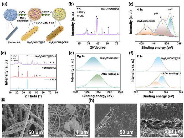
The CF/Li, NCNT@CF/Li, and MgF2/NCNT@CF-Li composite anodes were synthesized using a thermal melting method (Figs. S8-S10 in Supporting information). For pristine CF, molten Li shows limited wettability and does not spread well on the CF surface, indicating the lithiophobic nature of CF (Fig. S8). Nitrogen-doped CNT endows the carbon substrate lithiophilicity, and molten Li can infuse the NCNT@CF substrate within 10 min (Fig. S9). When MgF2/NCNT@CF is brought into contact with molten Li, an alloying reaction occurs (MgF2 + Li → LiMg + LiF), enabling uniform adsorption of molten Li into the host (Fig. S10). When the host was immersed in molten Li for 30 s, melting Li appeared at the central edge of the MgF2/NCNT@CF; when infiltration reached 3 min, Li filled the nanogaps due to the combined effects of enhanced lithiophilicity and capillary force of carbon nanotube, and the interconnect structure was still maintained. The smooth surface and dense structure of MgF2/NCNT@CF-Li are illustrated in Fig. 2h. As shown in Figs. S11 (Supporting information), EDS mapping reveals that the distribution of Mg does not perfectly align with that of F, suggesting that the thermal melting reaction results in the formation of Mg and LiF on the surface. The unique structure of MgF2/NCNT@CF-Li provided ample space to accommodate volume expansion, conducive to forming LiF-rich interphase, inducing a uniform Li plating process. The morphology of bare Li, CF/Li, and NCNT@CF/Li were also investigated in Figs. S12 (Supporting information). The bare Li, CF/Li, and NCNT@CF/Li all exhibit a flat surface, and the bare Li and NCNT@CF/Li show a dense structure (Figs. S12a-c and g-i). However, due to reduced lithiophilicity, the inner space of the carbon felt was not fully infiltrated by Li (Figs. S12d-f).
XRD was performed to identify further the surface composition of the MgF2/NCNT@CF-Li electrode. As depicted in Fig. 2d, typical peaks for Li metal appear at 36.2° and 64.9°, corresponding to the (110) and (200) plane (PDF #15–0401). The weakening of carbon peaks suggests that metallic Li has uniformly infiltrated the carbon framework during the thermal melting. MgF2/NCNT@CF-Li exhibits the characteristic peak of LixMg alloy at 35.4° (PDF #09–0215), indicating that metallic Mg, produced by the lithiation reaction of MgF2 at high temperature, further reacts with molten Li to form lithiophilic LixMg alloy. Lithiophilic LixMg alloy can reduce the nucleation overpotential during Li plating, promote the evenly nucleate process, and hinder Li dendrite growth. The peaks at 22.9° and 70.8° are correspond to Li3N (PDF #20–0759). Additionally, the peaks at 50.5° belong to Li2C2, which may be due to the compound formed when Li and carbon materials are in thermal equilibrium at the temperature of 693 K. A weak diffraction peak at 76.5° is also assigned to the (400) plane of LiMgN (PDF #06–0702), the compound of phase equilibrium of nitrogen compound, molten Li, and Mg at 693 K. Mo has proposed that LiMgN may be a passivation layer to protect Li [24]. XPS was also performed to investigate the surface information of MgF2/NCNT@CF-Li. Fig. S13 (Supporting information) shows the C 1s spectrum, with three peaks corresponding to C=C, C-Li, and C=O (Figs. S13c). Three peaks in the N 1s spectrum belong to the pyridine, pyrrole, and alkyl acetonitrile groups (Figs. S13d). In addition, peaks at 53.5, 54.2, and 54.9 eV in Li 1s spectra, which are assigned to Li3N, LixMg, and LiF, are consistent with the Mg 1s high-resolution spectrum. In addition, in the F 1s high-resolution spectrum, LiF (683.8 eV) and —CF3 group (686.7 eV) are observed, indicating the LixMg alloy, and LiF was formed from the reaction between molten Li and MgF2 (Figs. 2e and f).
To investigate the effect of the introduction of the NCNT and MgF2 into the carbon felt on Li deposition/dissolution, the morphology evolution of pristine CF and MgF2/NCNT@CF electrode are presented in Figs. S14 and S15 (Supporting information). The deposited Li shows a sheet-like structure when the discharge capacity is 15 mAh/cm2. As the plating continued, the deposited Li maintained a flat and dense morphology (Figs. S14a and b). Meanwhile, the Li layer shows a thickness of ~66 μm and ~82 μm at the deposited capacity of 15 and 20 mAh/cm2, respectively, indicating that the porous MgF2/NCNT@CF skeleton alleviates the volume expansion during cycling. In contrast, Li deposition on the pristine carbon felt results in a dendritic structure, the non-uniform deposition attributed to the lithiophobic carbon fibers. The dendrites grow larger when further plating to 20 mAh/cm2, forming a porous morphology (Figs. S15a and b). At the stripping state, the MgF2/NCNT@CF skeleton shows a smooth surface without "dead Li"; the Li metal is well confined in the structure in Figs. S14c and f. However, irregular Li residues on the carbon felt surface indicate that the Li metal cannot reversibly plating/stripping under high area capacity on the carbon felt (Fig. S15c). The above results imply the important role of the MgF2 and NCNT in stabilizing composite during the Li plating/striping process.
In addition, to demonstrate the electrochemical behaviors of the MgF2/NCNT@CF electrode, cyclic voltammetry (CV) was employed with MgF2/NCNT@CF as the cathode and the Li metal as the anode (Fig. S16 in Supporting information). The peak at 0.3 V may assigned to the formation of SEI, while the peak at 1.5 V is ascribed to the irreversible displacement reaction between Li and MgF2 (Li + MgF2 = 2LiF + Mg) [25]. From the second cycle, the MgF2/NCNT@CF presents reversible cycling, which can be assigned to the alloying/de-alloying process (Mg+Li ⇄ LixMgy) [26].
To investigate the Li plating behavior on the MgF2/NCNT@CF composite further, the morphology of various composite anodes after cycling was characterized by SEM. After 50 cycles at 1 mA/cm2, 1 mAh/cm2, bare Li shows a loose and porous structure with observable Li dendrites and mossy Li in Figs. 3a-c. The thickness of the porous layer reaches ~66 μm, resulting in the "hostless structure" of the bare Li, which undergoes severe volume expansion. The fragile SEI layer of bare Li creates random Li+ flux, promoting dendritic Li growth and leading to battery failure. For the CF/Li, as depicted in Fig. S17 (Supporting information), the deposited irregular floccules form a thick Li layer that covers the composite anode. The loose morphology arises from the lithiophobic carbon fiber, which cannot be combined with Li+ efficiently. Figs. 3d-f illustrate the morphology of NCNT@CF-Li after cycling; no needle-like Li or mossy Li formed on the surface, and the structural integrity is preserved. The presence of lithiophilic NCNT provides adequate sites to guide Li nucleate, resulting in unrestricted, spherical Li deposits with diameters of 8–9 μm.
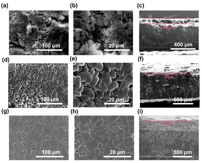
The MgF2/NCNT@CF-Li, by contrast, has a flat surface, and the Li sheet grows into a relatively smooth structure (Figs. 3g-i) while the structure integrity is preserved. The corresponding EDS mapping confirms the uniform distribution of Mg, C, and F elements on the surface (Fig. S18 in Supporting information). Mg element originates from the LixMg alloy, C from the carbon skeleton, and F from the LiF by the reaction between molten Li and MgF2/NCNT@CF skeleton; some comes from the decomposition of LiTFSI. These results verify that the LixMg alloy is distributed uniformly within the composite electrode, and the LiF-rich layer effectively inhibits the formation of Li dendrites, stabilizing the electrolyte/electrode interphase. The cross-sectional view displays that the porous structure can promote electrolyte infiltration, accelerate Li+ transportation, and mitigate volume expansion.
The skeleton-alloy-fluoride composite developed in this work imparts several advantageous features to the Li metal anode. According to the previous report, Li-Mg alloy can keep largely bulk intact after Li stripping, preserving bulk stability during high-capacity Li plating/stripping cycling [27]. Additionally, the lithiophilicity of the alloy, along with the N-contained functional group (pyridine N and pyrrole N), lowers the Li nucleation barrier and facilitates Li+ transportation at the electrode-electrolyte interphase.
The electrochemical performance of various anodes further identifies the interphase stability of the MgF2/NCNT@CF-Li composite anode. At 1 mA/cm2, 1 mAh/cm2, NCNT@CF-Li cell achieves a longer life span of up to 280 cycles, whereas the overpotential of the CF/Li significantly increases at < 170 cycles (Fig. S19 in Supporting information). Fig. 4a shows the voltage profiles of plating/stripping for symmetric cells operated on bare Li and MgF2/NCNT@CF-Li. The MgF2/NCNT@CF-Li exhibited stable plating and stripping for over 1000 h. In contrast, the bare Li exhibited large voltage polarization after 200 h. The comparative voltage hysteresis of the two symmetric cells is shown in Fig. 4b; the decay of the voltage hysteresis in the beginning cycles can be attributed to the stabilization process of the SEI at the electrode. XPS was conducted to verify the protection mechanism of the MgF2/NCNT@CF-Li electrode. XPS spectra illustrate C, F, and Li signals after 100 cycles at 1 mA/cm2, 1 mAh/cm2. For the cycled bare Li, the electrolyte-derived SEI, including COOR (288.6 eV) and C—OR (285.8 eV) in the C 1s spectrum (Fig. 4e) and LiF (685.2 eV) in the F 1s spectrum (Fig. 4d). In addition, Li2O (55.0 eV) can also be detected in the cycled pristine Li in Fig. 4c. The results are consistent with the composition reported in the previous SEI analysis [28]. Fig. S20 (Supporting information) also illustrates the chemical composition of NCNT@CF-Li after cycling, showing that the components, like the intrinsic SEI of the bare Li, indicate that the N-functional groups have little effect on electrolyte decomposition during cycling. By comparison, the relative ratio of LiF on the MgF2/NCNT@CF-Li composite anode is significantly higher, enabling more uniform regulation of Li deposition. The reduction of COOR and C—OR species in the C 1s spectrum and the elimination of Li2O in Li 1s illustrate the effectiveness of the MgF2/NCNT@CF-Li composite in reducing electrolyte decomposition.
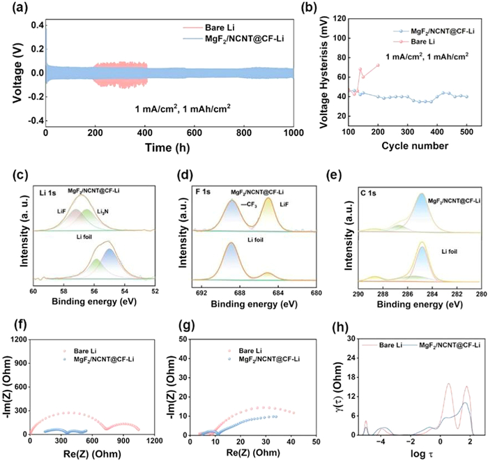
The improvement in surface stability of the MgF2/NCNT@CF-Li is further investigated by electrochemical impedance spectra (EIS) carried out before and after cycling in Figs. 4f and g. The converted DRT profiles are also presented in Fig. 4h and Fig. S21 (Supporting information). The peaks in the relaxation time range from 10–4 s to 10–2 s, corresponding to the process of Li+ transfer across the SEI, while the peaks in the range of 10–2–101 s represent the charge transfer process. The values of resistance of SEI (RSEI) and charge transfer (Rct) were dominated by integrating the corresponding peak. Before cycling, bare Li shows high RSEI (315 Ω), while the lower RSEI obtained with MgF2/NCNT@CF-Li (53 Ω), indicates that the LiF/LiMg hybrid interface on the composite anode effectively stabilized the Li/electrolyte interphase. After 50 cycles at 1 mA/cm2, 1 mAh/cm2, the MgF2/NCNT@CF-Li shows a lower Rct (4.6 Ω) in comparison with the Rct (13.9 Ω) of bare Li, which is assigned to the lithiophlicity of LiMg alloy and LiF on the surface of composite Li that enables high Li affinity to Li atoms and favorable charge transfer capability. However, the RSEI (1.1 Ω) of bare Li seems lower than that of MgF2/NCNT@CF-Li (2.3 Ω), which can be ascribed by the destruction of SEI, induced by the severe volume variation. The results are also consistent with cycling performance and morphology evolution, suggesting that the LiF-rich SEI proves interfacial stability.
To evaluate the electrochemical performance of the MgF2/NCNT@CF-Li composite anode, the coulombic efficiency and cycling stability were conducted by a galvanostatic measurement. Detecting Li-Cu coulombic efficiency provides insight into the electrochemical stability of the Li stripping/replating process on the various substrates. Fig. 5a compares the coulombic efficiency of MgF2/NCNT@CF||Li and Li||Cu batteries at 1 mA/cm2, 1 mAh/cm2. The MgF2/NCNT@CF demonstrates stable cycling performance, maintaining an average CE of 99.6% over 400 cycles. In comparison, Cu foil shows fluctuating CE, which declines after 10 cycles, revealing Li stripping/plating instability on the Cu foil. The corresponding voltage profiles are illustrated in Fig. S22 (Supporting information). The Li plating behavior of the MgF2/NCNT@CF electrode differs from the Cu foil (Figs. S22a and b). To investigate the Li plating/stripping behavior on the MgF2/NCNT@CF electrode, the higher capacity was employed in Fig. S22c. When the local voltage was above 0 V, lithium-ion intercalation was the dominant capacity contributor; the Li metal plating happened when the voltage went below 0 V. The results suggested that the hybrid Li-ion/Li metal operation on the MgF2/NCNT@CF electrode was previously reported on the hard carbon [29–31]. Fig. S23 (Supporting information) displays the coulombic efficiency of CF||Li and NCNT@CF||Li cells at 1 mA/cm2, 1 mAh/cm2. The coulombic efficiency of the CF begins to decay at 99 cycles and reaches 68% at 117 cycles. The NCNT@CF electrode can stabilize for 160 cycles at 99.0% and decay to 81% after 180 cycles, attributed to the accumulation of "dead Li" from the non-uniform Li deposition/dissolution at the carbon skeleton.
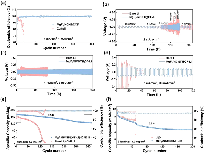
Symmetrical cells were used to investigate the electrochemical performance of composite anodes under different currents and capacities. Fig. 5b displays the rate capability of bare Li and MgF2/NCNT@CF-Li. The results confirm that the lower polarization of MgF2/NCNT@CF-Li at different current densities is due to the carbon skeleton's fast electron/ion transportation channel. By contrast, the polarization of the bare Li symmetrical cell gradually increases at 2 mA/cm2 and then fluctuates sharply and reaches 360 mV at 5 mA/cm2. Such large polarization indicates slow ion transport kinetics between Li electrodes at higher current density, which may be attributed to the thick SEI accumulation. The LiF-rich MgF2/NCNT@CF-Li electrode displays a smooth voltage plateau and lower polarization when the current is back to 1 mA/cm2 (~30 mV), which further confirms the LiF-rich SEI can protect the Li anode.
Fig. 5c shows the voltage-time profile of MgF2/NCNT@CF-Li and bare Li at 4 mA/cm2, 2 mAh/cm2. The hysteresis of the MgF2/NCNT@CF-Li anode remains stable at a voltage of 100 mV for > 200 h, while the Li increases to 200 mV after 20 h. Benefiting from the lithiophilic nitrogen-contained functional group to regulate Li nucleation at the beginning, the polarization of the NCNT@CF-Li anode fluctuates around 80 mV. However, the hysteresis increased to 190 mV after 200 h due to the lack of interphase protection (Fig. S24 in Supporting information). At an increased capacity of 10 mAh/cm2, the bare Li shows an unstable electrochemical performance when the cycling capacity in Fig. 5d. The NCNT@CF/Li shows a flat polarization curve at 40 h. After 45 h, a sudden voltage increase was detected for the NCNT@CF/Li electrode with oscillating voltage in the later cycles, implying the cell failed, which explained the severe dendrite growth and repeated SEI cracking/rebuilding process under a high capacity (Fig. S25 in Supporting information). By contrast, the MgF2/NCNT@CF-Li anode shows superiority. It can still work for 120 h with a flat voltage plateau and lower polarization (~150 mV). The unique 3D carbon structure of MgF2/NCNT@CF provides higher specific surface area and cross-link transfer channels for Li plating/stripping. Compared to other previously reported composite anodes, the MgF2/NCNT@CF-Li symmetric cell can obtain good Li plating/stripping stability in different area capacities (Table S1 in Supporting information). LiF-rich interphase prevents the crack of SEI, and the LixMg alloy interphase retains the integrity of the skeleton during cycling.
To evaluate the electrochemical performance of MgF2/NCNT@CF-Li anode in the corrosive carbonate-based electrolyte, the NCM811 cathode with a loading of 9.2 mg/cm2 was paired, and the cycling stability of the cells is shown in Fig. 5e. The Li||NCM811 cell exhibited a lower capacity of 145 mAh/g after 50 cycles, followed by a gradual capacity degradation attributed to increased impedance caused by unstable SEI. In contrast, the MgF2/NCNT@CF-Li||NCM811 cell maintained a high discharge capacity of ~124 mAh/g after 380 cycles. Meanwhile, the full cell with MgF2/NCNT@CF-Li shows stable charge-discharge voltage curves without obvious polarization owing to the stable interphase of the composite anode in Fig. S26 (Supporting information). In addition, a sulfur cathode was also chosen as the full-cell configuration to investigate the potential application of MgF2/NCNT@CF-Li anode in high-energy-density batteries. With a high loading of S cathode of 11.0 mg/cm2, the MgF2/NCNT@CF-Li||S cell delivers an initial discharge capacity of 11.8 mAh/cm2 at the current density of 2.0 mA/cm2 (Fig. 5f), the corresponding discharge-charge voltage profiles are shown in Fig. S27 (Supporting information). However, the specific capacity degraded fast initially, which may be ascribed to the severe loss of active materials induced by the "shuttle effect" in such a high S loading [32]. The bare Li||S cell shows a similar initial discharge capacity, while it drops to 2.1 mAh/cm2 at 50 cycles. The larger polarization of the corresponding voltage curves of the Li||S cell is illustrated in Fig. S28 (Supporting information), which can be explained by the accumulation of "dead Li", thus leading to increased impedance in the electrode/electrolyte interphase. The MgF2/NCNT@CF-Li||S cell remained at 3.9 mAh/cm2 after 200 cycles. In addition, the coulombic efficiency from 200 cycles was 95.0%, demonstrating the excellent interphase stability of composite electrodes at such high Li plating/stripping capacity.
In conclusion, we developed a multifunctional skeleton design for a composite electrode that effectively stabilizes the lithium metal anode. The synergistic interplay of the 3D porous carbon skeleton, Li-Mg alloy, LiF components, and lithiophilic sites within the MgF2/NCNT@CF-Li composite anode efficiently guides lithium deposition by reducing nucleation barriers and promoting lateral growth on the electrode surface. This composite electrode features a multifunctional structure, sufficient flexibility to maintain structural integrity under high lithium plating and stripping capacities, robust mechanical stiffness to inhibit dendrite growth, and a LiF-rich interphase that protects Li metal anode. Benefiting from the composition and structural features, the MgF2/NCNT@CF-Li composite anode can cycle for ~1000 h with low polarization at a current density of 1 mA/cm2, 1 mAh/cm2. Paired with high-loading sulfur cathodes, the full cell delivers a high initial areal capacity (11.8 mAh/cm2) and long cycle life (200 cycles) at 4 mA/cm2, as well as exhibiting 3.9 mAh/cm2 after 200 cycles. The rational design of skeleton—alloy—LiF electrode and its synergistic effect for stable electrochemical performance provide a new insight into applying a multifunctional composite host in stabilizing Li anode.
The authors declare that they have no known competing financial interests or personal relationships that could have appeared to influence the work reported in this paper.
Tianhui Li: Writing – original draft, Methodology, Investigation, Formal analysis, Data curation, Conceptualization. Meizhen Qu: Supervision, Resources, Formal analysis. Gongchang Peng: Resources, Methodology, Formal analysis. Hanxiao Zhou: Writing – review & editing, Resources, Investigation, Formal analysis. Zihao Su: Resources, Methodology, Formal analysis. Yi Chang: Supervision, Resources, Methodology. Bao Zhang: Supervision, Funding acquisition, Formal analysis, Conceptualization. Wei Sun: Validation, Supervision, Project administration, Investigation, Funding acquisition, Formal analysis.
We thank the Chengdu Institute of Organic Chemistry, University of Chinese Academic of Sciences, for help with the synthesis of carbon materials and sulfur cathode. W. Sun acknowledges the financial support from the National Natural Science Foundation of China (Nos. 52302221 and U2330119), the Sichuan Science and Technology Program (Nos. 2023NSFSC0116 and 2023ZYD0038). B. Zhang acknowledges the financial support from the Sichuan Science and Technology Program (No. 2025ZNSFSC0964). T. Li acknowledges the Sichuan Provincial Postdoctoral Science Foundation (No. W030241003003). The authors also appreciate technical support from the Analysis and Testing Center, University of Electronic Science and Technology of China.
Supplementary material associated with this article can be found, in the online version, at doi:
S.M. Wood, C. Fang, E.J. Dufek, et al., Adv. Energy Mater. 8 (2018) 1801427. doi: 10.1002/aenm.201801427
Z. Liang, D. Lin, J. Zhao, et al., Proc. Natl. Acad. Sci. U. S. A. 113 (2016) 2862–2867. doi: 10.1073/pnas.1518188113
Z. Liang, G. Zheng, C. Liu, et al., Nano Lett. 15 (2015) 2910–2916. doi: 10.1021/nl5046318
K. Yan, Z. Lu, H.W. Lee, et al., Nat. Energy 1 (2016) 2016010.
D. Lin, Y. Liu, Y. Cui, Nat. Nanotechnol. 12 (2017) 194–206. doi: 10.1038/nnano.2017.16
J. Du, W. Wang, M. Wan, et al., Adv. Energy Mater. 11 (2021) 2102259. doi: 10.1002/aenm.202102259
L. Fu, X. Wang, L. Wang, et al., Adv. Funct. Mater. 31 (2021) 2010602. doi: 10.1002/adfm.202010602
Y. Chen, Q. He, Y. Zhao, et al., Nat. Commun. 14 (2023) 8326–8337. doi: 10.1038/s41467-023-43163-9
Y. Huang, R. Li, S. Weng, et al., Energy Environ. Sci. 15 (2022) 4349–4361. doi: 10.1039/D2EE01756C
K.S. Jiang, G.M. Hobold, R. Guo, et al., ACS Energy Lett. 7 (2022) 3378–3385. doi: 10.1021/acsenergylett.2c01818
J. Guo, Z. Wen, M. Wu, J. Jin, Y. Liu, Electrochem. Commun. 51 (2015) 59–63. doi: 10.1016/j.elecom.2014.12.008
X.Q. Zhang, X.B. Cheng, X. Chen, C. Yan, Q. Zhang, Adv. Funct. Mater. 27 (2017) 1605989. doi: 10.1002/adfm.201605989
Y. Zhang, Y. Wu, H. Li, et al., Nat. Commun. 13 (2022) 1297–1308. doi: 10.1038/s41467-022-28959-5
Y. Zhao, T. Zhou, T. Ashirov, et al., Nat. Commun. 13 (2022) 2575–2584. doi: 10.1038/s41467-022-29199-3
Y. Zhao, T. Zhou, M. Mensi, J.W. Choi, A. Coskun, Nat. Commun. 14 (2023) 299–309. doi: 10.1038/s41467-023-35934-1
X. Cao, X. Ren, L. Zou, et al., Nat. Energy 4 (2019) 796–805. doi: 10.1038/s41560-019-0464-5
S. Chang, J. Fang, K. Liu, et al., Adv. Energy Mater. 13 (2023) 2204002. doi: 10.1002/aenm.202204002
X. Shen, X. Cheng, P. Shi, et al., J. Energy Chem. 37 (2019) 29–34. doi: 10.1016/j.jechem.2018.11.016
T. Li, S. Gu, L. Chen, et al., Small 18 (2022) 2203273. doi: 10.1002/smll.202203273
H. Yang, H. Zheng, H. Yu, et al., Nanoscale 14 (2022) 13722–13730. doi: 10.1039/D2NR04158H
L. Chen, G. Chen, X. Lin, et al., ACS Appl. Mater. Interfaces 15 (2023) 10273–10282. doi: 10.1021/acsami.2c21612
S.S. Chi, Y. Liu, W.L. Song, L.Z. Fan, Q. Zhang, Adv. Funct. Mater. 27 (2017) 1700348. doi: 10.1002/adfm.201700348
T. Li, J. Jiang, H. Zhou, et al., Diamond Relat. Mater. 130 (2022) 109391. doi: 10.1016/j.diamond.2022.109391
Y. Zhu, X. He, Y. Mo, Adv. Sci. 4 (2017) 1600517. doi: 10.1002/advs.201600517
S.Q. Li, L. Zhang, T.T. Liu, et al., Adv. Mater. 34 (2022) 2270181. doi: 10.1002/adma.202270181
Zhong Shi, Meilin Liua, J.L. Devang Naik, J. Gole, Power Sources 92 (2001) 70–80. doi: 10.1016/S0378-7753(00)00521-8
P. Gao, H. Wu, X. Zhang, et al., Angew. Chem. Int. Ed. 60 (2021) 16506–16513. doi: 10.1002/anie.202103344
K. Xu, Chem. Rev. 114 (2014) 11503–11618. doi: 10.1021/cr500003w
J. Park, J. In Jung, S. Ha, et al., Angew. Chem. Int. Ed. 63 (2024) e202409992. doi: 10.1002/anie.202409992
G. Zhou, Y. Zhao, C. Hu, et al., Nano Res. 16 (2022) 8368–8376.
H. Gong, Y. Chen, S. Chen, et al., ACS Energy Lett. 7 (2022) 4417–4426. doi: 10.1021/acsenergylett.2c02130
H.J. Peng, T.Z. Hou, Q. Zhang, et al., Adv. Mater. Interfaces 1 (2014) 1400227. doi: 10.1002/admi.201400227

Figure 1 Illustration of structure and Li plating behaviors of various substrates: (a) Bare Li, (b) NCNT@CF/Li, (c) MgF2/NCNT@CF-Li composite Li anode.

Figure 2 Characterization of MgF2/NCNT@CF and composite Li anode. (a) The preparation process of MgF2/NCNT@CF-Li. (b) XRD pattern of MgF2/NCNT@CF. (c) N 1s spectrum of MgF2/NCNT@CF. (d) XRD pattern of CF/Li, NCNT@CF/Li, and MgF2/NCNT@CF-Li. High resolution (e) Mg 1s and (f) F 1s XPS spectra of MgF2/NCNT@CF before and melting Li. SEM images of (g) MgF2/NCNT@CF and (h) MgF2/NCNT@CF-Li composite.

Figure 3 Morphology evolution of various Li anode. Top view and cross-sectional view of (a-c) bare Li, (d-f) NCNT@CF/Li anode, (g-i) MgF2/NCNT@CF-Li composite anode after 50 cycles at 1 mA/cm2, 1 mAh/cm2.

Figure 4 Surface composition analysis and ion kinetic transportation of the composite anode. (a, b) Galvanostatic cycling and voltage hysteresis at 1 mA/cm2, 1 mAh/cm2. (c) Li 1s, (d) F 1s, (e) C 1s XPS spectra of MgF2/NCNT@CF-Li anode and bare Li after 100 cycles for 1 mA/cm2, 1 mAh/cm2. (f, g) Nyquist plots of bare Li and MgF2/NCNT@CF-Li symmetric cell before and after cycling. (h) DRT analysis after cycling.

Figure 5 Electrochemical performance of Li and MgF2/NCNT@CF-Li. (a) Coloumbic efficiency of MgF2/NCNT@CF||Li and Li||Cu at 1 mA/cm2, 1 mAh/cm2. (b) Rate capability comparison. (c, d) Cycling stability of MgF2/NCNT@CF-Li and bare Li symmetrical batteries at 4 mA/cm2, 2 mAh/cm2 and 5 mA/cm2, 10 mAh/cm2. (e) cycling performance of MgF2/NCNT@CF-Li||NCM811 and Li||NCM811 full cells at 0.5 C rate. (f) Cycling performance of MgF2/NCNT@CF-Li||S and Li||S full cells.

 扫一扫看文章


扫一扫关注我们
 DownLoad:
 下载:
下载:
 下载:
下载: