mwu@uestc.edu.cn (M. Wu). 1 These authors contributed equally to this work.
Received Date:
26 February 2025 Accepted Date:
27 April 2025 Revised Date:
17 April 2025 Available Online:
15 August 2026
Abstract:
The low-temperature performance of lithium iron phosphate (LiFePO4) batteries remains a significant challenge. Electrolyte engineering has emerged as an effective strategy to address this issue efficiently. Herein, ethyl pentafluoropropionate (pFEP) is introduced into the carbonate-based electrolyte as a functional additive that enables LiLFP cells to cycle at −20 ℃ or even −40 ℃. Molecular dynamics (MD) simulations and spectroscopic characterization demonstrate that adding only 3% pFEP could effectively modify the electrolyte solvation structure, significantly increasing the content of contact ion pairs (CIPs) and aggregates (AGGs). This structural modification promotes the formation of a uniform LiF-rich interphase, which is crucial for improved battery performance. As a result, LiLFP cell with active cathode loading of 8.5 mg/cm2 delivers 117.2 mAh/g and cycling stability over 130 cycles at −20 ℃. This work provides a cost-effective strategy for enhancing the low-temperature performance of LFP batteries.
The rapid advancement of renewable energy sources and electric vehicles (EVs) has driven a growing demand for high-performance energy storage systems [1–3]. Among various electrochemical systems, lithium iron phosphate (LiFePO4, LFP) batteries have emerged as a prominent candidate [4–6]. However, the sluggish kinetics and severe capacity deterioration of LFP batteries at low temperature remain a significant challenge [7–9]. Addressing these limitations is crucial for expanding the applicability of LFP batteries in regions with harsh cold conditions.
Electrolyte engineering has emerged as a promising strategy to enhance the low-temperature performance of LFP batteries [10–12]. Novel strategies, such as designing high-concentration electrolytes (HCEs), localized high-concentration electrolytes (LHCEs), or fluorinated cosolvent-based electrolytes, have been shown to improve the low-temperature performance of LFP batteries by tuning the solvation structure [13]. For example, Han and co-workers utilized fluorinated reagents (diethyl fluoromalonate and fluoroethylene carbonate) with high-concentration LiFSI to enhance LFP battery performance at low temperature [14]. Similarly, Zhang's group reported that FEC as an electrolyte solvent was conducive to LFP battery operation in the range of −80~80 ℃ [15]. While fluorinated reagents improve low-temperature performance, their high cost remains a significant drawback. To address this, incorporating fluorinated additives into electrolytes to improve low-temperature performance has emerged as a highly promising strategy. Min's group certificated that the low-temperature performance of the battery could be improved by adding 2 wt% 4,4ʹ-sulfonyldiphenol and 5 wt% perfluoro n-butylsulfonyl fluoride to the traditional carbonate electrolyte [16]. Thus, to explore the best compromise between cost and low temperature performance of LFP batteries, it is necessary to explore new cost-effective fluorinated additives.
Herein, ethyl pentafluoropropionate (pFEP) with the merit of abundant fluorine content, excellent electrochemical stability was introduced into a carbonate-based electrolyte to investigate its potential in modifying the Li+ solvation structure and promoting the formation of LiF-rich interfaces at low concentrations. Theoretical calculation, molecular dynamics (MD) simulation and spectroscopic characterization confirmed that the solvation structure of the electrolyte can be changed when the amount of pFEP is only 3%. Specifically, the proportion of contact ion pairs (CIPs) and aggregates (AGGs) increases from 20% to 42% at −20 ℃, facilitating the formation of LiF-rich SEI/CEI layers that enhance interfacial stability and suppresses side reactions. As excepted, the Li||LFP cell with pFEP has high discharge capacity of 117.2 mAh/g at −20 ℃ and achieve long lifespan. This work demonstrates that pFEP is an effective additive for improving the low-temperature performance of LFP batteries and provides a cost-effective strategy for advancing energy storage systems in cold environments.
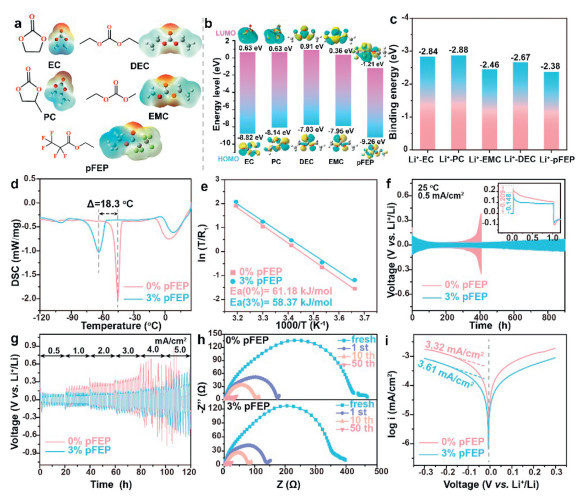
Considering the prospect of practical application of electrolyte, the common carbonate ester EC, PC, DEC and EMC are selected as solvents in this work (Fig. 1a). Among them, DEC and EMC have both low freezing point and low viscosity, which facilitate the modulation of low-temperature electrolytes (Table S1 in Supporting information). As shown in Fig. 1b and Fig. S1a (Supporting information), pFEP has the lowest HOMO energy level (−1.12 eV) and remains stable in the range of 2.0–4.0 V, indicating that pFEP is beneficial to enhance the antioxidant properties of the electrolyte [17]. The corresponding electrochemical stability windows of all electrolytes in Fig. S1b (Supporting information) confirm this theoretical calculation perspective. The low LUMO energy level of pFEP indicates a good tendency for pFEP to generate SEI layer on Li metal [21]. The low binding energy between Li+ and pFEP (−2.38 eV) is conducive to the de-solvation of Li+ at low temperature (Fig. 1c and Fig. S2 in Supporting information). Moreover, the physical properties of the electrolyte are also changed after adding 3% pFEP. As shown in Fig. 1d and Fig. S3 (Supporting information), DSC curves show that the freezing point of the electrolyte decreased from −45.2 ℃ to −63.5 ℃. The ionic conductivity and wettability of the electrolyte are also improved with 3% pFEP (Figs. S4 and S5 in Supporting information). Fig. 1e and Fig. S6 (Supporting information) exhibit the activation energies of Li+ de-solvation (Ea1) and diffusion kinetics in the SEI layer (Ea2), which evaluated through Arrhenius law and Li||Li symmetric batteries [18]. 3% pFEP electrolyte has the lower de-solvation energy barriers of 58.37 kJ/mol (Ea1) and 45.41 kJ/mol (Ea2), suggesting that the energy barrier of Li+ de-solvation and transport processes through the SEI obtain an obvious reduction in 3% pFEP [19] In 3% pFEP, the low binding energy of Li+-pFEP and low de-solvation energy barrier are beneficial to the de-solvation of Li+, so that the Li+ migration number reaches 0.68 (Fig. S7 in Supporting information) [20]. Above results indicates that pFEP has potential to improve the low-temperature performance of LFP batteries.
Figure 1
Figure 1.
(a) Molecular structures and electrostatic potential. (b) HOMO/LUMO orbital energy levels of solvents and pFEP. (c) Binding energy between Li+ and solvents/pFEP. (d) DSC curves. (e) Ea of Li+ de-solvation. (f) Cycling performance and (g) rate performance of Li||Li symmetrical cells at 25 ℃. (h) EIS profiles. (i) Tafel plots.
The galvanostatic cycling test of Li||Li symmetric cell was firstly used to evaluate the affinity of electrolyte to Li metal. Fig. 1f exhibits that 3% pFEP has the lower plating overpotential value of 148 mV in the initial cycle. Meanwhile, cell employing 3% pFEP electrolyte also demonstrate excellent interface stability even after 900 h of cycling at the current density of 0.5 mA/cm2 with a capacity of 0.5 mAh/cm2. In contrast, the cell with 0% pFEP electrolyte rapidly failed after 380 h with the initial plating overpotential of 209 mV. Li||Li symmetric cell with 3% pFEP also shows higher stability at −20 ℃ (Fig. S8 in Supporting information). Fig. 1g shows that the cell with 3% pFEP electrolyte demonstrates the prominent stability and superior rate performance. The resistance of two Li||Li cells after different cycles exhibits in Fig. 1h. Obviously, the cell in 3% pFEP electrolyte possesses smaller resistance than cell in 0% pFEP. As shown in Fig. 1i, the Tafel plot was used to investigate the charge transfer kinetics across the interface [21]. 3% pFEP has higher intrinsic exchange current density of 3.61 mA/cm2, which highlights that the 3% pFEP significantly accelerates the interfacial transfer kinetics [22].
The reversibility of Li plating and stripping was further evaluated by Li||Cu cells (Fig. S9 in Supporting information). Cyclic voltammetry (CV) curves show that 3% pFEP has higher current response in the process of Li plating/stripping. Meanwhile, the Li||Cu cell with 3% pFEP electrolyte sustains high average CE during the long-cycling. Above tests of Li||Li and Li||Cu cells identify that pFEP is beneficial to improve charge transfer and reaction kinetics, and elevate cycle life and rate performance [17].
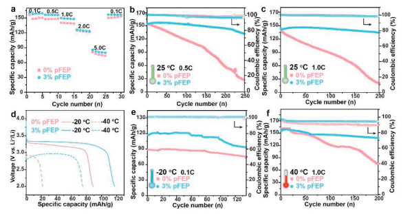
Based on the suitability tests with Li metal, the investigation of the compatibility between electrolytes and LFP cathode through systematic electrochemical tests is of great significance. Prior to cycling, the EIS plot of Li||LFP cells with different electrolytes exhibits that the Rct of cell with 3% pFEP (160 Ω) is significantly lower than that of the cell with 0% pFEP (280 Ω) (Fig. S10 in Supporting information). The rate performance of two Li||LFP cells under different current densities (1.0 C = 170 mAh/g, with the LFP cathode loading of ~8.5 mg/cm2) is shown in Fig. 2a and Fig. S11 (Supporting information). Cell with 3% pFEP electrolyte shows optimum rate performance, with specific capacities of ~158.9, 155.9, 148.4, 124.4, 81.61 mAh/g at 0.1, 0.5, 1.0, 2.0 and 5.0 C, respectively. This result matches well with the rate capacities of Li||Li symmetric cells, indicating that the pFEP additive can also work well at Li||LFP cells.
Figure 2
Figure 2.
(a) Rate performance of Li||LFP cells at 25 ℃. Long cycling curves of Li||LFP cells at (c) 25 ℃, 0.5 C; (d) 25 ℃, 1.0 C; (e) −20 ℃, 0.1 C; (f) 40 ℃, 1.0 C. (d) Discharge curves at −20 ℃ and −40 ℃.
To assess the applicability of these electrolytes at wide temperature, Li||LFP cells assembled with different electrolytes were cycled in the voltage range of 2.0–4.0 V (Figs. 2b-f, Figs. S12-S14 in Supporting information). At 25 ℃, Li||LFP cell with 3% pFEP displays high capacity retention (CR) of 85.4% (131.7 mAh/g, 0.5 C) and 97.5% (134.6 mAh/g, 1.0 C), which are higher than those of 0% pFEP (17.4% and 26.9 mAh/g at 0.5 C, 13.4% and 20.1 mAh/g at 1.0 C). Compared to the 0% pFEP electrolyte, the 3% pFEP also demonstrates superior electrochemical performance at −20 ℃ and −40 ℃, with discharge capacities reaching 117.2 and 75 mAh/g, respectively (Fig. 2d). Fig. 2e shows that after 135 cycles (−20 ℃), 3% pFEP electrolyte enables higher reversible capacity of 93.5 mAh/g and a stable Coulomb efficiency (CE) of 99.9%. This is due to the reversible insertion/deinsertion of Li ions in FePO4 /LiFePO4 during the discharge-charge process in 3% pFEP electrolyte (Fig. S15 in Supporting information). More importantly, at lower temperature down to −40 ℃, only Li||LFP cell using 3% pFEP can cycle stably at −40 ℃ with high CE. Fig. 2f exhibits the performance of Li||LFP cells at high temperature (40 ℃), and it can be found that 3% pFEP electrolyte also exhibit exceptional performance. After 200 cycles at 40 ℃, the capacities of cells with 0% pFEP electrolyte shows retention of 45.7% (74.2 mAh/g). In addition, the performances of LFP||Gr cells with two electrolytes were also tested (Fig. S16). Compared with 0% pFEP, LFP||Gr cells with 3% pFEP not only show good stability at 25 ℃ and 40 ℃, but also exhibit high discharge capacity at −20 ℃ (123.7 mAh/g) and −40 ℃ (56.8 mAh/g). In short, pFEP can effectively extend the use range of traditional carbonate electrolyte and support the operation of the Li||LFP and LFP||Gr cells at wide temperature (−40 ~ 40 ℃).
The Li||Li, Li||Cu and Li||LFP cells employing electrolyte with pFEP demonstrate better electrochemical performances. It is, therefore, necessary to obtain the in-depth effect of additive pFEP on the variation in Li+ solvation structure in the electrolyte. The solvation structures of 0% pFEP and 3% pFEP at different temperature were studied with MD simulation and NMR.
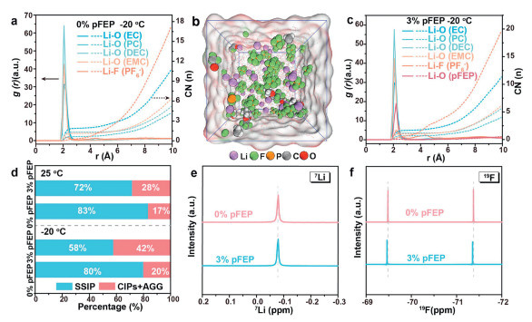
The detail information on the Li+ solvation structure was collected through the radial distribution functions (RDF) and coordination numbers (N(r)) from MD simulation (Figs. 3a-c, Figs. S17 and S18, Table S2 in Supporting information). Under both 25 ℃ and −20 ℃, in the 0% pFEP electrolyte, the solvation shell mainly comprises of EC, PC, DEC and EMC. Upon the introduction of pFEP in 0% pFEP electrolyte, the peak of Li-O(pFEP) appears at 2.2 Å at both 25 ℃ and −20 ℃, indicating that pFEP penetrate the first solvation sheath of Li+. The coordination numbers at 25 ℃ corresponding to the EC, PC, DEC, EMC and PF6- in 0% pFEP are 1.67, 0.69, 1.18, 1.14 and 1.41, respectively. At −20 ℃, the solvent coordination number is higher. Notably, at both 25 ℃ and −20 ℃, the corresponding coordination number of EC, PC, DEC, EMC in 3% pFEP are reduced (Table S3 in Supporting information). The high coordination number of the solvent indicates that the SEI film generated in 0% pFEP is mainly composed of organic components [23,24]. In addition, the coordination number of PF6- also changed significantly with the introduction of pFEP. The coordination number of PF6- increases from 1.53 to 1.61 at 25 ℃ and from 1.11 to 2.36 at −20 ℃, respectively. The modification in the solvation structure by pFEP also has profound implications for the ratio of solvent-separated ion pair (SSIPs), CIPs and AGGs in the electrolyte. As shown in Fig. 3d, the proportion of CIPs and AGGs increases from 17% to 28% at 25 ℃ (from 20% to 42% at −20 ℃).
Figure 3
Figure 3.
RDF and CN of (a) 0% pFEP and (c) 3% pFEP at −20 ℃. (b) MD simulation snapshot of 3% pFEP at −20 ℃. (d) Corresponding distributions of the solvate species of two electrolytes. (e) 7Li and (f) 19F NMR spectra of 0% pFEP and 3% pFEP.
Meanwhile, after dissolving 3% pFEP into the basic electrolyte, the PF6−···Li+ coordination was further characterized using NMR. Figs. 3e and f are 7Li and 19F NMR spectra, respectively. For the 7Li spectra, as the pFEP content increases, a upfield shift of the characteristic peak is observed, indicating that the interaction of Li+-anion and the electron-cloud density around Li+ are enhanced, which is consistent with the downshift observed in 19F spectra [25]. Both MD and NMR suggest that pFEP enhances anion coordination within the electrolyte, contributing to the improved electrochemical performance and the generation of inorganic-rich SEI layer.
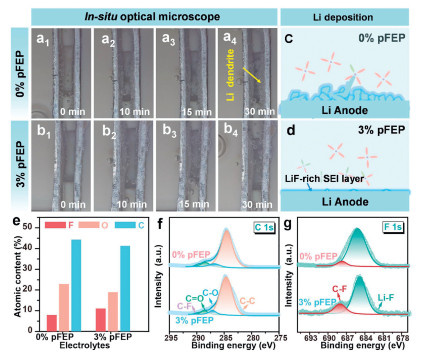
The effects of the pFEP on the Li deposition morphology and SEI composition were investigated by in situ optical microscopy, scanning electron microscope (SEM) and X-ray photoelectron spectroscopy (XPS) systematically. As shown in Figs. 4a and b, it can be found that 0% pFEP electrolyte was adversed to the Li homogeneous deposition with rapid development of dendrites within 30 min, while no obvious dendrite growth in 3% pFEP electrolyte even after 30 min. Fig. S19 (Supporting information) shows SEM images of Li deposited onto the Cu foil at different temperatures (−20, 25, 40 ℃). For 0% pFEP electrolyte, the deposited Li exhibits an uneven distribution with Li dendrite observed clearly at all temperatures. In contrast, the 3% pFEP electrolyte did not generate such uniform morphology of Li deposition, which is favorable to reduce the side reactions and enhance the CE of Li||Cu cell. Analogously, in Li||Li symmetric cell, there are many cracks and holes on the surface of Li metal in 0% pFEP, while the electrode surface in 3% pFEP is more compact and smoother (Figs. S20 and S21 in Supporting information). In addition, the thickness and roughness of the inactive Li layers (Li||LFP cells) formed in different electrolytes after 200 cycles at 25 ℃ can be used to evaluate the homogeneity of SEI layer, since that the thickness of dead Li reduces with increase of uniformity of SEI layer [26]. As shown in Fig. S22 (Supporting information), the thickness of the inactive Li layer in 3% pFEP is 25.5 µm, which is less than the thickness of 0% pFEP (58.5 µm). This result matches well with the electrochemical performance of Li||LFP cells.
Figure 4
Figure 4.In-situ optical microscope images of Li metal in (a) 0% pFEP and (b) 3% pFEP. Schematic evolutions of Li deposition in (c) 0% pFEP and (d) 3% pFEP. (e) Distribution of elements on Li anodes in Li||LFP cells after 200 cycles at 25 ℃. (f) XPS C 1s curves. (g) XPS F 1s curves.
X-ray photoelectron spectroscopy (XPS) was further carried out to analyze the SEI compositions. The full XPS spectra in Fig. S23 (Supporting information) suggest that Li, P, C, O and F elements exist on the surface of Li anode in the two electrolytes. Figs. 4e exhibits the corresponding content of F, C and O elements. Among the two electrolytes, the content of F in 3% pFEP (11.08%) electrolyte is higher than that in 0% pFEP (7.92%). Meanwhile, 3% pFEP has low content of C and O elements. C 1s spectra in Fig. 4f display four peaks, corresponding to C—C, C—O, C=O, and C-F bonds [27,28]. Combined with the C content, it can be found that the SEI layer in 3% pFEP has the least organic components (ROLi, ROCOLi and Li2CO3etc.), which is match well with the MD simulation. F 1s spectra exhibit two peaks at 685.1 eV and 687.5 eV (Fig. 4g), attributing to Li-F and C-F bonds [24,29]. Hence, due to the LUMO energy level of pFEP and the unique solvation structure of 3% pFEP, the 3% pFEP electrolyte promotes the generation of LiF-rich SEI layer on the surface of Li metal, which augmenting the cycling stability of the cell at wide temperature (Figs. 4c and d).
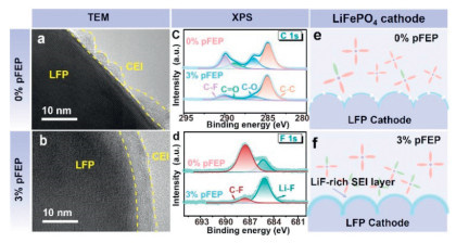
In order to characterize the microstructure changes of LFP and cathode-electrolyte interface, the morphologies and surface chemical composition of the LFP cathodes after 200 cycles at room temperature were observed under SEM, TEM and XPS. SEM image of the pristine LFP power in Fig. S24 (Supporting information) show that the surface of LFP is smooth. However, after 200 cycles, the surfaces of LFP in 0% pFEP electrolyte are covered with thick electrolyte decomposition products, which impeding interfacial charge transfer as evidenced by the EIS (Figs. S25 and S26 in Supporting information). In contrast, the LFP cycled in 3% pFEP demonstrates a clean surface (Fig. S25). As illustrated in Figs. 5a and b, TEM images of the cycled LFP cathodes are used to obtain the morphology of the CEI layers. A homogeneous and smooth CEI layer measuring 6.0 nm in thickness is identified in 3% pFEP, which is in favour of maintain the stability of LFP and inhibit side reactions. By contrast, 0% pFEP samples show amorphous CEI layer on the LFP cathodes, indicating that adverse reactions occur on the corresponding LFP electrode surface.
Figure 5
Figure 5.
TEM images of LFP cathodes in Li||LFP cells after 200 cycles at 25 ℃ in (a) 0% pFEP and (b) 3% pFEP. (c) XPS C 1s curves and (d) XPS F 1s curves. Schematic evolutions of CEI layer in (e) 0% pFEP and (f) 3% pFEP.
The XPS technology was subsequently conducted on LFP cathodes to obtain the chemical composition of CEI layer. XPS survey spectra of two samples confirm the presence of C, O, F, P and Li elements (Fig. S22). And 3% pFEP has high content of F (6.36%), which is superior than 0% pFEP (3.14%). Moreover, it can be seen that 3% pFEP owns high content of LiF and the least organic component (Figs. 5c and d). TEM and XPS results together prove that 3% pFEP electrolyte is conducive to forming a LiF-rich, smooth and uniform CEI layer on the surface of LFP cathode during the cycle process (Figs. 5e and f).
In summary, the low-temperature performance of LiFePO₄ (LFP) batteries using a 1.0 mol/L LiPF₆ electrolyte in EC/PC/DEC/EMC (2:1:2:2 by volume) is significantly enhanced by incorporating only 3% ethyl pentafluoropropionate (pFEP). The pFEP additive can not only reduce the energy barrier for Li+ de-solvation but also accelerate the formation of the anion-dominated solvation structure and increase the content of CIPs and AGGs. Meantime, XPS and TEM characterizations prove that the existence of pFEP contribute to the LiF-rich SEI/CEI layers. Consequently, the assembled Li||LFP cell with pFEP exhibits an excellent performance at −20 ℃ with a high discharge capacity of 117.2 mAh/g. Even at a low temperature of −40 ℃, the cell matches with LFP can still maintain a capacity of 75 mAh/g. This work offers a cost-effective strategy for advancing the performance of LiFePO4 batteries at low temperature.
Declaration of competing interest
There are no conflicts to declare.
CRediT authorship contribution statement
Caili Xu: Writing – review & editing, Writing – original draft, Investigation, Formal analysis, Data curation, Conceptualization. Ming Zhang: Writing – original draft, Validation, Software, Data curation. Pengyu Li: Validation, Data curation. Cheng Chen: Writing – review & editing, Writing – original draft, Software, Data curation, Conceptualization. Haiping Zhou: Writing – review & editing, Funding acquisition. Shu Zhang: Writing – review & editing, Writing – original draft, Supervision, Funding acquisition. Mengqiang Wu: Writing – review & editing, Supervision, Data curation.
Acknowledgment
The authors are grateful for the financial support from Projects of Science & Technology Department of Sichuan Province (Nos. 2024ZDZX0033 and 2024-YF08-00062-GX).
Supplementary materials
Supplementary material associated with this article can be found, in the online version, at doi:10.1016/j.cclet.2025.111263.
[1]
B. Song, L. Su, X. Liu, et al., Electron 1 (2023) e13. doi: 10.1002/elt2.13
[2]
Q. Liu, Z. Zheng, P. Xiong, et al., Electron 2 (2024) e72. doi: 10.1002/elt2.72
[3]
Y. Ji, L. Dong, J. Liu, et al., Energy Environ. Sci. 17 (2024) 4078–4089. doi: 10.1039/d4ee00115j
[4]
X. Ren, Y. Li, Z. He, X. Xi, X. Shen, J. Energy Storage 74 (2023) 109305. doi: 10.1016/j.est.2023.109305
Figure 1
(a) Molecular structures and electrostatic potential. (b) HOMO/LUMO orbital energy levels of solvents and pFEP. (c) Binding energy between Li+ and solvents/pFEP. (d) DSC curves. (e) Ea of Li+ de-solvation. (f) Cycling performance and (g) rate performance of Li||Li symmetrical cells at 25 ℃. (h) EIS profiles. (i) Tafel plots.
Figure 3
RDF and CN of (a) 0% pFEP and (c) 3% pFEP at −20 ℃. (b) MD simulation snapshot of 3% pFEP at −20 ℃. (d) Corresponding distributions of the solvate species of two electrolytes. (e) 7Li and (f) 19F NMR spectra of 0% pFEP and 3% pFEP.
Figure 4In-situ optical microscope images of Li metal in (a) 0% pFEP and (b) 3% pFEP. Schematic evolutions of Li deposition in (c) 0% pFEP and (d) 3% pFEP. (e) Distribution of elements on Li anodes in Li||LFP cells after 200 cycles at 25 ℃. (f) XPS C 1s curves. (g) XPS F 1s curves.
Figure 5
TEM images of LFP cathodes in Li||LFP cells after 200 cycles at 25 ℃ in (a) 0% pFEP and (b) 3% pFEP. (c) XPS C 1s curves and (d) XPS F 1s curves. Schematic evolutions of CEI layer in (e) 0% pFEP and (f) 3% pFEP.


 DownLoad:

 下载:
下载:


 下载:
下载:

