Received Date:
19 January 2025 Accepted Date:
05 March 2025 Revised Date:
27 February 2025 Available Online:
15 June 2026
Abstract:
Lithium/fluorinated graphite (Li/CFx) primary batteries with great energy density advantages still struggle to realize large-scale applications, due to the sluggish cathode reaction kinetics accompanied by poor rate capability and power density. One key challenge arises from the inert electronic structure of CFx predominated by covalent C–F bond, which results in poor intrinsic electronic conductivity. To address this issue, cathode surface activation engineering is proposed to modify CFx with hybrid transitional metal oxide/carbon layer, which is derived by one-pot pyrolysis of structurally designable metallic ionic liquids (Bmim[MCln], M = Fe, Al, Cu, Zn, etc.). Generally, the presence of metal oxides induces generation of highly conductive semi-ionic C–F species, cooperating with abundant oxygen vacancies and carbon matrix to synergistically improve electronic/ionic conduction and accelerate CFx conversion kinetics, while the Bmim[FeCl4]-derived system is the optimal solution. As expected, the surface activated CFx cathode achieves nearly 4 times the power density (22,581 W/kg at 14 C) of pristine CFx and higher conversion depth. This metallic ionic liquid-derived surface activation design efficiently regulates the intrinsically inert electronic structure of CFx cathode, and widens its chemical design space of metal oxides as composite components, furthermore, providing a universal solution for electrodes faced with electronic conduction challenges.
Lithium primary batteries (LPBs) based on fluorinated graphite (CFx) cathode are widely employed in military (e.g., radio frequency transmitters), medical (e.g., implantable devices) and other fields, due to advantages such as extremely high theoretical energy density (~2180 Wh/kg at cathode level) benefited from conversion-type mechanism involving multi-electron transfer and light elemental composition, wide operating temperature range (−40~80 ℃), and ultralong storage life (~0.5% capacity decay per year) [1–3]. However, their commercialization is restricted to low-power (tens of W) scenarios up until now, while potential applications in urgently required high-power devices are severely impeded by sluggish cathode reaction kinetics, which results in poor rate capability and power density, severe voltage hysteresis, and low conversion depth, etc. This kinetics dilemma is caused by multiple factors, such as low intrinsic electronic and ionic conductivities of CFx material, insoluble LiF deposition behavior during discharge process that passivates the CFx cathode surface, and side reactions occurring at the cathode/electrolyte interface [4–6]. Amongst, the electronic conduction bottleneck originating from inert electronic structure is regarded as the foremost issue, which foremost impedes the CFx conversion at a high rate. Essentially, CFx is composed of multiple fluorinated nanodomains with distinct C—F bond characteristics, while the covalent bond takes up a predominant proportion [7–9]. However, as compared to other bond types including semi-ionic and ionic bonds, the covalent C—F bond accompanied by sp3-hybridized carbon atoms and localized electrons possesses the shortest bond length and strongest bond energy, inevitably delivering the lowest electronic conductivity [10,11].
Recently, considerable efforts have been devoted to break the electronic conduction bottleneck of CFx by regulating its intrinsically inert electronic structure [1,12]. For example, low-temperature fluorination helps to partially retain the sp2 hybridization characteristic of the original graphite raw material, and more, generates a higher proportion of semi-ionic C—F bond, which possess relatively high electronic conduction ability owing to delocalized electrons at the out-of-plane pz orbitals of conjugated C═C bonds [13,14]. Nevertheless, in this case the improvement of conductivity and discharge rate is obtained at the expense of specific capacity due to the decreased F/C ratio, when achieving balanced CFx cathodes remains elusive. Meanwhile low-temperature process is still a challenging technology [15]. Considering the scale-application feasibility, composting CFx with heterogeneous conductive materials (e.g., carbon, manganese oxides, conducting polymers) in the form of surface coating should be a more practical solution [16–20]. Zhang group coated CFx with carbon by pyrolyzing its mixture with polyvinylidene fluoride (PVDF), significantly improving its discharge behavior at a high rate [19]. Shi group has demonstrated that coating metallic state Mn5O8 on CFx cathode can improve electronic conduction behavior to address the low power density issue [20]. Especially, manganese oxide family has been proven to efficiently induce the conversion of covalent C—F bond into semi-ionic bond [20–22]. However, conventional physical mixing technologies usually suffer from poor solid–solid heterogeneous interface that hinders electronic/ionic conduction, and are difficult to achieve uniform coating layer with controllable thickness or mass ratio. More significantly, besides well-known manganese oxides, it is worth exploring wider chemical space to discover more potential transitional metal oxides as composite component for CFx cathode. Notably, ionic liquids have been widely employed in electrochemical systems due to unique physicochemical and electrochemical properties [23,24]. Especially, the structures and properties of metallic ionic liquids composed of various organic cations and metallic anions can be tailored through molecular design.
Based on above considerations, herein surface activation engineering was proposed for CFx cathode by chemically modifying it with hybrid transitional metal oxide/carbon layer. Remarkably, structurally designable metallic ionic liquids with the common 1-butyl-3-methylimidazolium cation yet various metallic anions (Bmim[MCln], M = Fe, Al, Cu, Zn, etc.) were chosen as the precursor of modification layer, which can be converted into metal oxide nanoparticles (Fe2O3, Al2O3, CuO, ZnO, etc.) encapsulated in carbon matrix after one-pot pyrolysis. Moreover, owing to π–π interaction between imidazole rings and unfluorinated carbon, liquid-phase metallic ionic liquids could uniformly coat solid CFx with precisely controlled mass; therefore, the generated metal oxide and carbon species can in-situ chemically modify the CFx surface with ideal heterogeneous interface, superior to poor physical mixing interface. The presence of metal oxide could induce the generation of highly conductive semi-ionic C–F bond, meanwhile abundant oxygen vacancies (Ov) together with carbon matrix further improved the electronic/ionic conduction. After activating electronic structure, the conversion kinetics of CFx cathode was obviously accelerated, when the Bmim[FeCl4]-derived system delivered the highest power density accompanied by the highest conversion depth, meanwhile widening the chemical design space of transitional metal oxides composited with CFx cathode.
The synthetic route of surface activated CFx cathodes with chemical modification layer is illustrated in Fig. 1a and described in Supporting information in detail. Firstly, four kinds of metallic ionic liquids (CFx@Bmim[MCln], M = Fe, Al, Cu, Zn, etc.) were generated by heterogeneous reactions between corresponding anhydrous metal chlorides and BmimCl. Then, CFx materials were uniformly mixed with Bmim[MCln] under controllable mass (10% volume ratio of ionic liquids in alcohol solvent by default), to generate CFx@Bmim[MCln] as the precursor. After one-pot pyrolysis under O2 atmosphere, metallic ionic liquids were converted into metal oxide nanoparticles (Fe2O3, Al2O3, CuO, ZnO, etc.) encapsulated in carbon matrix, which in-situ chemically modified the CFx cathode surface. The obtained surface activated CFx modified with hybrid metal oxide/carbon layer (CFx@Fe2O3/C, CFx@Al2O3/C, CFx@CuO/C, CFx@ZnO/C, etc.) were finally applied as cathodes in LPBs.
Figure 1
Figure 1.
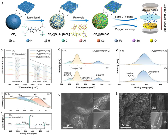
(a) Schematic synthesis route of the surface activated CFx cathodes based on metallic ionic liquids (Bmim[MCln], M = Fe, Al, Cu, Zn, etc.) and their applications in LPBs. (b) FT-IR spectra of pristine CFx and four kinds of CFx@Bmim[MCln]. High-resolution (c) C 1s, (d) F 1s, (e) Fe 2p, and (f) survey XPS spectra of CFx and CFx@Bmim[FeCl4]. SEM images of (g) CFx and (h) CFx@Bmim[FeCl4] (inset: SEM and TEM images) at various magnifications.
The chemical structures of pristine CFx and four kinds of CFx@Bmim[MCln] were firstly explored by Fourier transform infrared (FT-IR) spectra (Fig. 1b). All samples exhibit a strong absorption band centered at 1213 cm−1, which is the characteristic stretching vibration of covalent C—F bond [25]. After introducing imidazolium anion, a series of absorption bands between 2800 cm−1 and 3200 cm−1 emerged [26]. Concretely, the three bands between 2850 cm−1 and 3000 cm−1 are assigned to the alkyl chain of [Bmim]+ while others belong to the C—H asymmetric stretching modes of imidazole rings, all are not affected by metallic anions. Furthermore, a series of CFx@Bmim[FeCl4]-5/10/20 modified with various amounts of Bmim[FeCl4] (corresponding 5%, 10%, and 20% volume ratios of ionic liquids in alcohol solvent respectively, while 10% is the default value) were compared. The characteristic absorption band of imidazolium anion is found to intensify obviously as the modification mass increases (Fig. S1 in Supporting information). Moreover, the X-ray diffraction (XRD) patterns of CFx@Bmim[MCln] exhibit no additional characteristic diffraction peaks in addition to the peak around 41° assigned to the (100) reflection of CFx, due to the low modification mass and amorphous nature of ionic liquids (Fig. S2 in Supporting information) [27]. The variation of Fe content in the CFx@Bmim[FeCl4] system is proven by inductively coupled plasma optical emission spectrometry (ICP-OES), which exhibits a similar growing trend with the volume ratio of Bmim[FeCl4] in alcohol solvent (Fig. S3 in Supporting information). For simplification, CFx@Bmim[FeCl4]-10 is named as CFx@Bmim[FeCl4] thereafter, similarly for corresponding surface activated CFx after pyrolysis.
Detailed chemical environment was studied by X-ray photoelectron spectroscopy (XPS), to analyze surface chemical species states and respective contents. High-resolution C 1s XPS spectra of both CFx and CFx@Bmim[FeCl4] exhibit bonding states assigned to CFx, which are mainly deconvoluted into four subpeaks: inactive C–F2/C–F3 (291.9 eV), covalent C—F (290.1 eV), semi-ionic C—F (287.5 eV), and C—C/C═C species (284.8 eV) with decreasing binding energies (BEs), while the covalent C–F species hold the majority (Fig. 1c) [28]. It was found that the modification of Bmim[FeCl4] has little influence on the carbon species states of CFx, due to relatively low mass ratio. Concerning F 1s XPS spectra, both samples show two main peaks at 688.6 and 689.6 eV indexed to covalent C—F and inactive C–Fx species, respectively (Fig. 1d) [25]. In the Fe 2p spectra, two strong subpeaks at 723.5 and 711.3 eV correspond to Fe 2p1/2 and Fe 2p3/2, respectively, in addition to two satellite peaks located at 717.8 and 727.9 eV (Fig. 1e) [29]. Moreover, the survey spectrum of CFx@Bmim[FeCl4] exhibits additional identified peaks of Fe, N, and Cl elements as compared to pristine CFx, further evidencing the successful modifying of Bmim[FeCl4] on CFx (Fig. 1f).
As revealed by scanning electron microscopy (SEM) images under various magnifications, CFx exhibits layered morphology assembled by flake-like units with a whole size of about 5 μm, largely retaining the pristine morphology of graphite raw material (Fig. 1g, Figs. S4a and b in Supporting information). Related energy dispersive spectrometry (EDS) mapping patterns confirm the uniform distribution of C and F elements (Figs. S4c–e in Supporting information). CFx@Bmim[FeCl4] exhibits similar morphology accompanied by uniform distribution of additional Fe and N elements, which confirms the uniform modification of Bmim[FeCl4] on CFx surface benefitted from π–π interaction and is coincided with the XPS survey spectrum (Fig. 1h and Fig. S5 in Supporting information). CFx@Bmim[AlCl4], CFx@Bmim[CuCl3], CFx@Bmim[ZnCl3] exhibited similar architectural and elemental distribution characteristics, with corresponding modified metallic ionic liquids (Fig. S6–S8 in Supporting information).
Concerning four kinds of surface activated CFx obtained after pyrolysis, no obvious morphology changes or agglomeration behavior was found as compared with precursors (Fig. 2a and Fig. S9 in Supporting information). The transmission electron microscopy (TEM) image accompanied by ring-type selected area electron diffraction (SAED) pattern of pristine CFx demonstrate its layered and amorphous nature, being consistent with literature reports (inset of Fig. 1g and Fig. S4f in Supporting information) [30]. After being modified with Bmim[FeCl4], obvious heterogenous interface was observed (inset of Fig. 1h). Concerning CFx@Fe2O3/C, the high-resolution TEM (HRTEM) image gives detailed microstructural and interfacial feature that hybrid Fe2O3/carbon layer is uniformly modified on CFx surface. And the interplanar plane spacing of 0.251 nm corresponds to the (110) lattice plane of Fe2O3 phase (Fig. 2b). Three concentric diffraction rings in the SAED pattern are also assigned to the (214), (116) and (110) planes of Fe2O3, showing typical polycrystalline nature, meanwhile TEM-EDS mapping patterns give similar conclusions to those based on TEM-EDS (Fig. 2c) [27,31]. In the circular region of the HRTEM image, the short-range ordered structure corresponding to graphite can be observed, indicating the formation of carbon matrix (Fig. 2b) [32]. Generally, Raman spectra of carbon materials exhibit two broad peaks at 1340–1360 cm–1 and 1580–1600 cm–1, corresponding to the D-band associated with structural defects and the G-band derived from in-plane stretching vibration between adjacent C—C bonds [33]. No peaks are observed in the Raman spectrum of pristine CFx, due to the highly fluorinated surface with low electronic conductivity that renders it Raman-inactive [4]. By contrast, the D- and G-bands (with ID/IG = 1.03) in CFx@Fe2O3/C confirm the formation of carbon matrix with sp2-hybridized carbon atoms (Fig. S10 in Supporting information). The hybrid metal oxide/carbon layer in-situ formed by pyrolysis possess well heterogeneous interface that would benefit to electronic/ionic conduction, as compared to conventional physical mixing interface.
Figure 2
Figure 2.
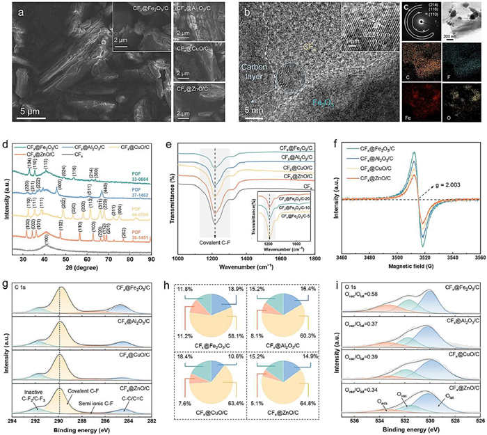
(a) SEM images of various surface activated CFx. (b) TEM (inset: HRTEM) images, (c) SAED and EDS mapping patterns of CFx@Fe2O3/C. (d) XRD patterns, (e) FT-IR spectra (inset: CFx@Fe2O3/C with various modification mass), (f) EPR spectra, (g) high-resolution C 1s XPS spectra with (h) relative proportions of different species, and (i) O 1s XPS spectra of various surface activated CFx.
XRD pattern of CFx@Fe2O3/C exhibits a series of peaks at 33.2°, 35.6°, 49.5°, 54.1°, etc., which are assigned to the (104), (110), (024), (116), etc. planes of hexagonal Fe2O3 (JCPDS card No. 33–0664) (Fig. 2d) [31]. Moreover, the peak intensify of Fe2O3 increases as the modification mass of metallic ionic liquid increases (Fig. S11 in Supporting information). It further evidences that Bmim[FeCl4] has been converted into Fe2O3 and amorphous carbon after pyrolysis. Similarly, XRD patterns of CFx@Al2O3/C, CFx@CuO/C and CFx@ZnO/C also reveal diffraction peaks of Al2O3, CuO, and ZnO phases, respectively [34–36]. In addition, FT-IR patterns show that the stretching vibration band of covalent C–F species for surface activated CFx is weakened to some extent, indicating the variation of electronic structure with the modification layer, meanwhile the CFx@Fe2O3/C with various modification mass also distinctly reflects this phenomenon (Fig. 2e).
XPS survey spectra further evidence the elemental compositions of four kinds of surface activated CFx (Fig. S12 in Supporting information). High-resolution Fe 2p spectra of CFx@Fe2O3/C can be deconvoluted into spin-orbit double peaks and relevant satellite peaks. Among them, the main subpeaks located at 711.5 and 724.6 eV were assigned to Fe3+, accompanied by weak subpeaks assigned to Fe2+, being consistent with the above SAED and XRD patterns (Fig. S13 in Supporting information) [37]. According to C 1s spectra, CFx@Fe2O3/C possesses the highest proportion (11.2%) of semi-ionic C—F species and delivers the largest improvement as compared to pristine CFx, while those of CFx@Al2O3/C (8.1%), CFx@CuO/C (7.6%), and CFx@ZnO/C (5.1%) decrease in order (Figs. 2g and h). Meanwhile, their proportions of covalent C—F and inactive C—F2/C—F3 species also decrease to varying extent, and CFx@Fe2O3/C gains the lowest values. When compared with semi-ionic C—F species, covalent C—F and C—F2/C—F3 species are relatively difficult to cleave and react with lithium ions due to higher bond energy during cathode process, being the foremost reason of electronic conduction blocking. Thus, the existence of transitional metal oxides can induce generation of semi-ionic bond, which would be favorable to electronic conduction and reaction kinetics of surface activated CFx cathodes at a high rate, especially for CFx@Fe2O3/C. Moreover, the main peak dominated by covalent C—F species of CFx@Fe2O3/C shifts to lower BE side as compared to other three samples, indicating its lowest average valence and weakest covalence. CFx@Fe2O3/C also possesses the lowest proportion of inactive C–F species in F 1s XPS spectra, being consistent with the C 1s spectra (Fig. S14 in Supporting information). Similarly, its covalent C—F peak also shifts to lower BE side to reveal an electronic transfer from the Fe2O3 to CFx, which endows C—F species with more electrochemical activity. The above results reveal an efficient regulation effect on the intrinsically inert electronic structure of CFx, which should be attributed to its electronic interaction with modified metal oxides and would significantly benefit electronic conduction.
The O 1s XPS spectra can be fitted into lattice oxygen (Olat) around 530.0 eV, Ovac at 531.8 eV, and surface adsorbed H2O and O2 species (Oads) at 533.4 eV, with increasing binding energies (Fig. 2i) [38]. Remarkably, the Ovac/Olat atomic ratio of CFx@Fe2O3/C (0.58) is significantly higher than that of CFx@Al2O3/C (0.37), CFx@CuO/C (0.39), and CFx@ZnO/C (0.34), demonstrating a high Ov level. The existence of Ov can create more active sites for lithiation, and more importantly, enhance the electronic conduction and ionic diffusion within metal oxides or across heterogenous interface, to reinforce the rate capability and power density of surface activated CFx cathodes in addition to highly conductive semi-ionic C–F bond [39,40]. Electron paramagnetic resonance (EPR) spectra also verify that under a magnetic field of 3515 Gauss, CFx@Fe2O3/C shows a stronger signal than those of other three samples at g = 2.003, further confirming its abundant Ov (Fig. 2f) [41].
Galvanostatic discharge curves of LPBs with surface activated and pristine CFx cathodes are compared at various rates, with a constant cut-off voltage of 1.5 V. The CFx cathode delivers a high discharge specific capacity of 656 and 443 mAh/g at 1 C (865 mA/g based on the theoretical specific capacity) and 2 C, respectively (Fig. 3a). However, it suffers from obvious capacity fade when the rate increases to 4 C, meanwhile severe voltage hysteresis and polarization phenomena occur accompanied by sharp dropped and unstable discharge voltage plateau. When compared with the theoretical discharge voltage (>4.5 V), the lower actual voltage is primarily attributed to the poor electronic/ionic conductivity of CFx, the formation of LiF passivation layer on cathode surface, and irreversible intermediate formation and decomposition processes [1,42]. Furthermore, it cannot properly discharge at 6 C or higher rate. It clearly demonstrates the unsatisfied rate capability of CFx cathode, when the low intrinsic electronic conductivity originating from inert electronic structure should be a breakthrough [20].
Figure 3
Figure 3.
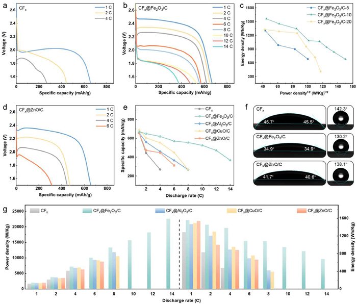
Galvanostatic discharge curves of LPBs with (a) CFx, (b) CFx@Fe2O3/C, and (d) CFx@ZnO/C cathodes at different discharge rates. (c) Ragone plots of CFx@Fe2O3/C cathodes with various modification mass. Comparisons on (e) specific capacities, (f) contact angles with (left) electrolyte and (right) deionized water, (g) power and energy densities of various surface activated and pristine CFx cathodes.
By contrast, all surface activated cathodes achieve improved rate capability to varying extent, which are influenced by the mass and components of hybrid metal oxide/carbon modification layers. After in-situ pyrolysis under O2 atmosphere, metallic ionic liquids can be converted into modification layer with ideal solid–solid heterogeneous interface that benefits to electronic/ionic conduction [43]. On one hand, a series of CFx@Fe2O3/C cathodes with various modification mass were compared, while Bmim[FeCl4]-10 (Bmim[FeCl4] for simplification) exhibits the optimal discharge behavior. (Fig. 3b and Fig. S15 in Supporting information) Accordingly, it possesses the highest power density and energy density (Fig. 3c and Fig. S16 in Supporting information). It is reasonable because Fe2O3 and carbon components provide almost no capacity above 1.5 V, excessive modification inevitably reduces the mass specific capacity from the whole cathode perspective, meanwhile excessively prolonging the migration distance of Li+. However, insufficient Bmim[FeCl4] precursor cannot guarantee well surface activation effect. Similarly, CFx@ZnO/C-10 also exhibits the optimal discharge performance as compared to CFx@ZnO/C-5/20 (Fig. 3d and Fig. S17 in Supporting information). Besides, when compared with pristine CFx, the CFx@Bmim[FeCl4] precursor as a cathode also exhibits enhanced discharge performance to some extent, due to improved interfacial ionic transfer that mitigates the inherent kinetics limitations of CFx, but is still inferior to CFx@Fe2O3/C (Fig. S18 in Supporting information).
On the other hand, CFx@Fe2O3/C is significantly superior to other cathodes under the same modification mass. Generally, at a low rate of 1 C, all the four kinds of surface activated CFx cathodes output specific capacities of more than 600 mAh/g, yet without advantage over pristine CFx (Figs. 3a, b, d and e, Fig. S19 in Supporting information). However, their voltage plateaus are much higher than that of CFx, meaning the alleviating of voltage hysteresis and polarization to varying extent, when CFx@Fe2O3/C performs best (2.4–2.5 V). As the rate increases, their discharge behaviors begin to differentiate: CFx@ZnO/C firstly falls behind at 2 C followed by CFx@Al2O3/C at 4 C, CFx@CuO/C maintains relative advantages over the above two until 6 C, but accelerates to decay at higher rate. CFx@Fe2O3/C maintains absolute advantages in all stages, for example, their specific capacities at the same 6 C are 312, 365, 449, and 571 mAh/g, respectively. CFx@Fe2O3/C delivers a maximum valid discharge rate as high as 14 C, when the corresponding voltage plateau is still stabilized at 1.8 V. By contrast, the maximum valid discharge rates for CFx@Al2O3/C, CFx@CuO/C, and CFx@ZnO/C cathodes are only 8, 8, and 6 C, respectively.
Generally, CFx@Fe2O3/C achieves a maximal power density of 22,581 W/kg at 14 C at cathode level, which significantly surpasses CFx@Al2O3/C (11,824 W/kg at the highest rate of 10 C), CFx@CuO/C (10,536 W/kg at 8 C), and CFx@ZnO/C (8815 W/kg at 6 C), and reaches nearly 4 times that of pristine CFx (5867 W/kg at 4 C) (Fig. 3g and Fig. S20 in Supporting information). The surface activation engineering endows CFx cathode with significantly improved rate capability and power density, which is mainly attributed to the chemically modified transitional metal oxides that induce generation of highly conductive semi-ionic C—F bond and possess abundant Ov, accompanied by the carbon matrix. The synergistic effect of above multiple factors successfully accelerates electronic/ionic conduction and promotes CFx conversion kinetics. Moreover, among the four kinds of metallic ionic liquids, the Bmim[FeCl4]-derived system becomes the optimal solution owing to its highest semi-ionic C—F bond proportion and Ov level. Generally, the power density of CFx@Fe2O3/C is at a remarkable level as compared to other reported CFx-based cathodes (Table S1 in Supporting information). Besides, the surface activation engineering enables CFx to gain smaller contact angles (34.9°–41.2° vs. 45.6°) with electrolyte (Fig. 3f and Fig. S21 in Supporting information). The better wettability brought by modification layer can promote electrolyte permeation as well as Li+ diffusion. Similar improved wettability with deionized water demonstrates its potential in aqueous battery system.
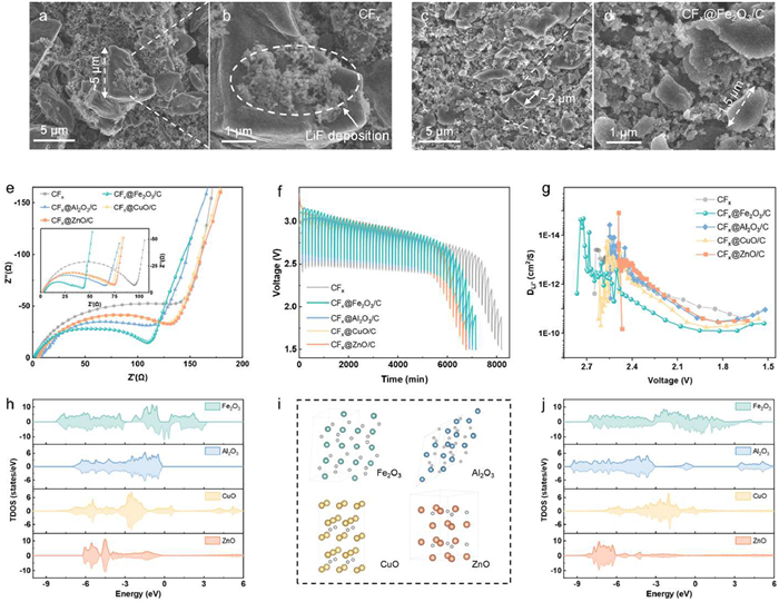
The cathode microstructural evolution behaviors after discharge process were compared, to investigate the effect of surface activation engineering on conversion reaction process. As revealed by SEM images, the discharged CFx cathode presents the coexistence of both small fragmented particles and large layered flake-like structures, partially retaining the originally layer morphology of pristine CFx to indicate incomplete lithiation process (Figs. 4a and b). During discharge process CFx would be covered by lithiation product LiF, whose insulating characteristic inevitably results in cathode surface passivation by hindering electronic conduction and ionic diffusion into inner bulk cathode [44]. Moreover, low conversion depth results in larger decomposed product sizes with longer conduction distance, which further impedes the conversion reaction [45]. In contrast, the discharged CFx@Fe2O3/C cathode is consisted of predominantly small particles, which indicates higher conversion depth and is consistent with the above electrochemical data (Figs. 4c and d). Similar phenomena are also observed for CFx@Al2O3/C, CFx@CuO/C, and CFx@ZnO/C cathodes (Fig. S22 in Supporting information). The morphology differences should be attributed to accelerated electronic conduction and conversion reaction kinetics benefitted from surface activation engineering.
Figure 4
Figure 4.
SEM images of discharged (a, b) CFx and (c, d) CFx@Fe2O3/C cathode pieces at various magnifications. (e) EIS Nyquist plots of batteries with surface activated and pristine CFx cathodes before and (inset) after discharge process. (f) GITT curves and (g) calculated DLi+ of various cathodes. (h) TDOS of Fe2O3, Al2O3, CuO and ZnO. (i) Atomic structures and (j) TDOS of Fe2O3, Al2O3, CuO and ZnO with Ov.
Electrochemical impedance spectroscopy (EIS) of LPBs were tested to directly compare the charge transfer behavior, while the depressed semicircle at mid-to-low-frequency in the Nyquist plots corresponds to charge transfer impedance (Rct), and the followed linear Warburg tail at high-frequency reflects bulk ion diffusion resistance (Rw) [46]. The Rct value of the battery with CFx@Fe2O3/C is significantly lower than those of other surface activated and pristine cathodes, for both before and after discharge process (Fig. 4e). It further evidences its electronic conduction advantages accompanied by largely accelerated reaction kinetics. Besides the highly conductive semi-ionic C–F bond, the intrinsically electronic conductivities of metal oxides determined by electronic structures should also be a key factor. Total density of states (TDOS) of Fe2O3, Al2O3, CuO, and ZnO were calculated by density functional theory (DFT), when Fe2O3 is found to possess the highest electronic state density near the Fermi level, in either with or without Ov case (Figs. 4h–j). Especially, Fig. 4i shows the atomic structures with Ov using the supercell method. These results further contribute to the highest rate capability and power density for the CFx@Fe2O3/C cathode.
To comprehensively evaluate the conversion reaction kinetics, the lithium-ion diffusion coefficients (DLi+) were calculated using the galvanostatic intermittent titration technique (GITT). Generally, each battery was discharged for 10 min at constant 0.1 C followed by a 2-h open-circuit period to reach steady-state voltage (Fig. 4f). According to the single-step GITT curves, DLi+ can be calculated from the slope of the linear range after the current pulse by Fick's second law (Fig. S23 in Supporting information). The DLi+ level of CFx@Fe2O3/C (10−10–10−12 cm2/s) is higher than those of other surface activated and pristine CFx (10−11–10−13 cm2/s) cathodes (Fig. 4g). Beyond improved electronic conduction, the semi-ionic C—F bond with lower dissociation energy also benefits the ion diffusion as compared to covalent C—F bond. Thus CFx@Fe2O3/C with highest semi-ionic C—F bond and Ov level also demonstrates the optimal ionic conduction [30,47].
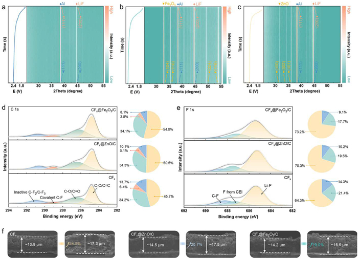
The phase evolution rules of cathodes during conversion reaction process were measured using in-situ XRD. For all cathodes, in addition to the diffraction signals of the Al (JCPDS card No. 04–0787) foil current collector, two sharp peaks around 38.6° and 44.9° emerged at highly overlapped locations during discharge process, corresponding to the (111) and (200) planes of LiF (JCPDS card No. 45–1460) respectively, that is the conversion product of CFx (Fig. 5a) [48]. Additionally, two weak peaks around 42° and 47° observed are assigned to the (205) and (207) planes of Al2O3 (JCPDS card No. 51–0769), which originate from the surface oxidation of Al foil (Fig. S24 in Supporting information) [34]. For CFx@Fe2O3/C, the extra diffraction peaks assigned to (104), (110), (024), (116), etc. planes of Fe2O3 basically maintained unchanged without obvious shift or decay (Fig. 5b) [27]. It confirms the phase and interfacial stability of Fe2O3 components as its lithiation does not occur above 1.5 V, despite effective regulations on the electronic structure and discharge behavior of CFx cathode. It also verifies that cathode capacity should be contributed by the CFx. More importantly, the full-width at half-maximum (FWHM) of the LiF peak is found to be broader as compared to pristine CFx, suggesting an amorphization tendency after modifying with Fe2O3. As discussed above, insoluble and insulating LiF accumulated on CFx surface inevitably passivates the cathode during discharge process, by hindering surface electronic/ionic conduction and further conversion of inner cathode. The amorphization of LiF can alleviate the passivation effect to some extent, and increase the conversion depth to release more capacity. Similarly, the stabilization of metal oxide phases as well as amorphization of LiF product were also observed in the in-situ XRD patterns of CFx@Al2O3/C, CFx@CuO/C, and CFx@ZnO/C cathodes (Fig. 5c, Figs. S25 and S26 in Supporting information).
Figure 5
Figure 5.In-situ XRD patterns of (a) CFx, (b) CFx@Fe2O3/C, (c) CFx@ZnO/C cathodes during discharge process. High-resolution XPS spectra on (d) C 1s and (e) F 1s states of discharged CFx, CFx@Fe2O3/C and CFx@ZnO/C cathodes with relative proportions of different species. (f) Cross-sectional SEM images of various cathode pieces (left) before and (right) after lithiation.
XPS depth profiling of the discharged cathodes gives the evolution rules of chemical states. After discharging to 1.5 V, the peak at ~284.8 eV corresponding to C—C/C═C species dominates the C 1s XPS spectra of all samples, due to generation of graphitic/amorphous carbon products, accompanied by the C—O/C═O species at ~286.4 eV from the decomposition products of polymer binder and electrolyte (Fig. 5d, Figs. S27a and S28a in Supporting information) [49,50]. The proportions of covalent C—F species are reduced to varying extent as compared to undischarged state, and the residual signals indicate incomplete conversion of CFx, meanwhile the inactive C—F2/C—F3 species still persisted. Overall, the discharged CFx@Fe2O3/C cathode demonstrates the lowest proportion of unreacted C–F species (11.9%), much lower than that of pristine CFx (20.1%) and other surface activated cathodes. Its superior conversion depth (~88%) indicates more lithiated CFx and higher cathode utilization during discharge process. In the F 1s spectra, the discharged CFx@Fe2O3/C cathode also shows the highest proportion of Li–F species, together with the least residual C—F species, which correlates with the C1s spectra (Fig. 5e, Figs. S27b and S28b in Supporting information). It is attributed to the best electronic and ionic conduction ability of as reflected by EIS and GITT, benefiting from the chemical modification of Fe2O3/C layer derived from Bmim[FeCl4] that efficiently regulates intrinsically inert electronic structure of CFx. That well explains its optimal rate capability and power density.
In addition, the cross-sectional morphologies of cathode pieces before/after discharge process were compared, to evaluate the expansion behavior during lithiation which greatly influences the battery architectural stability. All the surface activated cathodes expanded by approximately 20% after discharging to 1.5 V, meeting the demand for possible practical applications, and being lower than that of CFx (~25%) (Fig. 5f and Fig. S29 in Supporting information). It was attributed to the existence of surface modification layers without capacity contribution in this voltage interval, partially constraining the inner volume change of cathodes.
In summary, we proposed surface activation engineering for CFx cathode, to break its electronic conduction bottleneck arose from inert electronic structure predominated by covalent C—F bond. Utilizing structurally designable metallic ionic liquids as precursors, a hybrid transitional metal oxide/carbon layer was in-situ chemically modified on CFx surface. Various metal oxide components induced the generation of highly conductivity semi-ionic C—F species, which cooperated with abundant Ov as well as carbon matrix to synergistically accelerate the electronic/ionic conduction and CFx conversion kinetics to varying extent. Thus, the Bmim[FeCl4]-derived surface activated CFx cathode achieved nearly 4 times the power density (22,581 W/kg at 14 C) of pristine CFx and optimal CFx conversion depth (88%). This metallic ionic liquid-derived surface activation engineering enabled high-power CFx cathode via efficient electronic structure regulation, further provides a universal solution for electrode materials being challenged by low electronic conductivity and power density.
Declaration of competing interest
The authors declare that they have no known competing financial interests or personal relationships that could have appeared to influence the work reported in this paper.
CRediT authorship contribution statement
Bingxu Chen: Writing – original draft. Lei Yi: Resources, Data curation. Ruixi Xie: Writing – original draft, Visualization, Data curation. Rui Gao: Resources. Jia Yu: Writing – review & editing, Supervision, Funding acquisition, Conceptualization. Siqi Shi: Writing – review & editing, Supervision, Funding acquisition.
Acknowledgments
This work was supported by National Natural Science Foundation of China (Nos. 22279077, U2030206, 22479093), Natural Science Foundation of Shanghai (No. 22ZR1424500).
Supplementary materials
Supplementary material associated with this article can be found, in the online version, at doi:10.1016/j.cclet.2025.111040.
C. Sun, Y. Feng, Y. Li, et al., Nanoscale 6 (2014) 2634–2641.
[50]
X. Miao, J. Yang, W. Pan, et al., Electrochim. Acta 210 (2016) 704–711.
Figure 1
(a) Schematic synthesis route of the surface activated CFx cathodes based on metallic ionic liquids (Bmim[MCln], M = Fe, Al, Cu, Zn, etc.) and their applications in LPBs. (b) FT-IR spectra of pristine CFx and four kinds of CFx@Bmim[MCln]. High-resolution (c) C 1s, (d) F 1s, (e) Fe 2p, and (f) survey XPS spectra of CFx and CFx@Bmim[FeCl4]. SEM images of (g) CFx and (h) CFx@Bmim[FeCl4] (inset: SEM and TEM images) at various magnifications.
Figure 2
(a) SEM images of various surface activated CFx. (b) TEM (inset: HRTEM) images, (c) SAED and EDS mapping patterns of CFx@Fe2O3/C. (d) XRD patterns, (e) FT-IR spectra (inset: CFx@Fe2O3/C with various modification mass), (f) EPR spectra, (g) high-resolution C 1s XPS spectra with (h) relative proportions of different species, and (i) O 1s XPS spectra of various surface activated CFx.
Figure 3
Galvanostatic discharge curves of LPBs with (a) CFx, (b) CFx@Fe2O3/C, and (d) CFx@ZnO/C cathodes at different discharge rates. (c) Ragone plots of CFx@Fe2O3/C cathodes with various modification mass. Comparisons on (e) specific capacities, (f) contact angles with (left) electrolyte and (right) deionized water, (g) power and energy densities of various surface activated and pristine CFx cathodes.
Figure 4
SEM images of discharged (a, b) CFx and (c, d) CFx@Fe2O3/C cathode pieces at various magnifications. (e) EIS Nyquist plots of batteries with surface activated and pristine CFx cathodes before and (inset) after discharge process. (f) GITT curves and (g) calculated DLi+ of various cathodes. (h) TDOS of Fe2O3, Al2O3, CuO and ZnO. (i) Atomic structures and (j) TDOS of Fe2O3, Al2O3, CuO and ZnO with Ov.
Figure 5In-situ XRD patterns of (a) CFx, (b) CFx@Fe2O3/C, (c) CFx@ZnO/C cathodes during discharge process. High-resolution XPS spectra on (d) C 1s and (e) F 1s states of discharged CFx, CFx@Fe2O3/C and CFx@ZnO/C cathodes with relative proportions of different species. (f) Cross-sectional SEM images of various cathode pieces (left) before and (right) after lithiation.

 DownLoad:

 下载:
下载:


 下载:
下载:
