Citation:
Linfeng Peng, Cong Liao, Jiayue Peng, Shuai Chen, Tianyu Lei, Shijie Cheng, Jia Xie. Effect of oxygen doping sources on enhancing air stability and lithium metal compatibility of Li5.5PS4.5Cl1.5 electrolyte[J]. Chinese Chemical Letters,
2026, 37(6): 111015.
doi:
10.1016/j.cclet.2025.111015
Effect of oxygen doping sources on enhancing air stability and lithium metal compatibility of Li5.5PS4.5Cl1.5 electrolyte
English
Effect of oxygen doping sources on enhancing air stability and lithium metal compatibility of Li5.5PS4.5Cl1.5 electrolyte
State Key Laboratory of Advanced Electromagnetic Technology, School of Electrical and Electronic Engineering, Huazhong University of Science and Technology, Wuhan 430074, China
Received Date:
21 November 2024 Accepted Date:
27 February 2025 Revised Date:
25 February 2025 Available Online:
15 June 2026
Abstract:
Oxygen (O) doping is a promising strategy for enhancing the air stability and lithium metal compatibility of sulfide solid electrolytes (SSEs). However, the impact of various O sources on the structure and properties of SSEs remains unclear. In this study, we synthesized a series of O-doped electrolytes, Li5.5PS4.5-xOxCl1.5 (LPSCOx, 0.1 ≤ x ≤ 0.5), using Li2O and P2O5 as O sources, and systematically investigated their differences in structure, air stability, and electrochemical properties. O preferentially substitutes sulfur (S) at the 16e site and begins to replace S at the 4d site once a certain O concentration is reached. Notably, the P2O5-doped electrolytes (P-LPSCOx) exhibit a greater oxygen tolerance content (0.24) at the 16e site, along with better air stability, higher ionic conductivity, and superior lithium metal compatibility. XRD, SEM, and XPS analyses reveal that the P2O5-doped electrolytes exhibit larger cell parameters, higher densification, and fewer side reactions with lithium metal compared to the Li2O-doped counterparts. This study provides valuable insights into the development of high-performance O-doped sulfide electrolytes.
All-solid-state batteries (ASSBs) use non-flammable inorganic solid electrolytes and have the potential to incorporate lithium metal anodes, providing both high safety and high energy density [1–4]. Solid electrolytes (SEs) are essential components in ASSBs, and their development plays a crucial role in the practical progress of the ASSBs. Among various SEs, the sulfide solid electrolytes (SSEs) have emerged as promising candidates for ASSBs owing to their high room-temperature (RT) ionic conductivity and favorable mechanical properties [4–8]. However, their practical application is significantly challenged by poor air stability and incompatibility with lithium metal [1,9–11]. Element doping has been identified as a potent strategy to enhance the properties of SSEs [12–14]. Among various dopants, oxygen has shown considerable promise [10,15–23].
Li2O and P2O5 are principal O sources for implementing doping strategies in SSEs [18,24–27]. Recent researches indicate that substituting Li2S/P2S5 with Li2O/P2O5 within the argyrodite electrolyte framework significantly enhances air stability and lithium metal compatibility [18,24,25,27]. The formation of oxysulfides through O introduction bolsters moisture tolerance, underscoring the essential role of O doping in enhancing chemical stability. In the case of Li6PS5Br with O doping, a more stable interphase consisting of Li2O and Li3OBr forms at the lithium surface during cycling, resulting in higher critical current density (CCD) and extended cycling life compared to pristine argyrodite electrolytes [27]. However, the Li6PS5Cl system reveals that the CCD of Li/Li6PS4.75O0.25Cl/Li cell is marginally lower than that of Li/Li6PSCl/Li cell [25], indicating limitations in Li2O doping for dendrite suppression. Our previous work demonstrated that a P2O5 doping strategy in Li5.5PS4.5Cl1.5 electrolyte notably enhances the air stability and compatibility with high-voltage cathode [24]. Li2O and P2O5 are also used as O sources to modify the Li2S−P2S5 sulfide electrolyte system (including Li2O−Li2S−P2S5 [28,29] and Li2S−P2S5−P2O5 [30–32]) and other SSEs (Li10GeP2S12 [33], Li3PS4 [26], and Li7P3S11 [34]). Although both Li2O and P2O5 serve as O sources, their different impacts on the structure and properties of SSEs are yet to be fully understood, necessitating further research.
In this work, Li5.5PS4.5Cl1.5 (LPSCl1.5) electrolyte with high ionic conductivity and relatively low cost is selected to systematically evaluate the effects of Li2O and P2O5 doping on the structure and properties of SSE. P2O5-doped electrolytes (P-LPSCOx) outperforming Li2O-doped ones (L-LPSCOx) across air stability and lithium metal compatibility. The higher air stability of the P2O5-doped electrolytes arises from the increased O content (0.24) at the 16e site, which reduces the amount of unstable P-S bonds. Furthermore, the P2O5-doped electrolytes exhibit smoother and denser surfaces after cold pressing, contributing to the suppression of lithium dendrites. The Li//Li symmetric cells using P-LPSCOx demonstrating higher CCDs and stable cycling. Additionally, the NCM622/SE/Li full cells employing P-LPSCO0.3 exhibit superior rate capabilities and cycling stability at both RT and 50 ℃. X-ray photoelectron spectroscopy (XPS) detected fewer by-products at P-LPSCO0.3/Li interface after cycling.
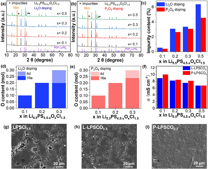
The crystal structures of the prepared electrolytes Li5.5PS4.5-xOx Cl1.5 (x = 0.1, 0.2, 0.3, and 0.5) were analyzed via X-ray diffraction (XRD). Figs. 1a and b display the XRD patterns of Li2O- and P2O5-doped electrolytes (denoted as L-LPSCOx and P-LPSCOx). The prominent diffraction peaks correspond to the argyrodite structure [35,36], confirming the successful synthesis of O-doped electrolytes. However, as O content increases, peaks associated with the impurity LiCl become evident. To obtain more accurate crystal structure information, the XRD data were refined simultaneously with the Rietveld method by Fullprof. The refinement results are provided in Fig. S1 and Tables S1-S9 (Supporting information). The relative impurity content increases with increased O concentration. Noticeably, P2O5-doped electrolytes show lower impurity levels compared to their Li2O-doped counterparts at the same O doping content. Specifically, the impurity contents for P-LPSCO0.1, P-LPSCO0.2, P-LPSCO0.3, and P-LPSCO0.5 are 0.41%, 2.65%, 3.08%, and 4.55%, while for L-LPSCO0.1, L-LPSCO0.2, L-LPSCO0.3, and L-LPSCO0.5, the respective values are 0.55%, 3.09%, 3.35%, and 6.37% (Fig. 1c and Table S9). Additionally, P2O5-doped electrolytes exhibit larger cell parameters (Fig. S2a and Table S9 in Supporting information), which may contribute to the higher ionic conductivity [36].
Figure 1
Figure 1.
XRD patterns of Li5.5PS4.5-xOx Cl1.5 (x = 0.1, 0.2, 0.3, and 0.5) electrolytes with (a) Li2O and (b) P2O5 as oxygen source. Results from XRD Rietveld refinement: (c) Percentage content of impurities in the prepared electrolyte structures, oxygen content at 4d and 16e sites in (d) Li2O and (e) P2O5 doping electrolytes. (f) Ionic conductivity values of the above SEs. SEM images of the pelleted (g) LPSCl1.5, (h) L-LPSCO0.3, and (i) P-LPSCO0.3 electrolytes.
XRD refinement of LPSCl1.5 indicates that S occupies three distinct sites (4a, 4d, and 16e) within the structure (Fig. S2b and Table S10 in Supporting information), consistent with previous studies [35]. The refinement patterns and parameters for the O-doped electrolytes (x = 0.1, 0.2, and 0.3) are detailed in Figs. S1a-f and Tables S1-S6, with calculations presented in Figs. 1d and e. At x = 0.1 and 0.2, all O atoms occupy 16e site, regardless of the O source. At x = 0.3, O atoms are distributed between the 16e and 4d sites, with the ratios being 0.2/0.1 for L-LPSCO0.3 and 0.24/0.06 for P-LPSCO0.3. These findings suggest that (1) O preferentially replaces S at the 16e site, as reported in the literature; (2) replacement of S at the 4d site occurs once a threshold concentration of O is reached; and (3) P2O5-doped electrolytes have a higher O tolerance content at the 16e site (0.24 vs. 0.2).
Furthermore, the impact of different O sources on the chemical structure was analyzed using Raman (Fig. S3 in Supporting information) and NMR spectroscopy (Fig. S4 in Supporting information). The Raman peaks at 190, 260, 421, 570 and 600 cm-1 correspond to the P-S bond in PS43- units of the O-doped electrolytes, aligning with previous findings [16]. In our recent study [37], the LPSCl1.5 electrolyte displays a peak at 426 cm-1, while significant shifts in the O-doped electrolyte suggest that O incorporation affects PS43- vibrations due to the incorporation of O at the 16e site [25], consistent with the XRD refinement results. The 31P MAS NMR spectra and fitted curves of L-LPSCO0.3 and P-LPSCO0.3 are presented in Figs. S4a and b. The observed four different contributions of Cl4, SCl3, S2Cl2, and S3Cl in both electrolytes relate to the number of nearest neighboring Cl/S atoms surrounding the PS43- tetrahedra at the 4d site [38]. The high relative intensity of SCl3, S2Cl2, and S3Cl (no S4) implies a substantial degree of structural disorder in L-LPSCO0.3 and P-LPSCO0.3. Variations in the relative intensities of SCl3 and S2Cl2 reflect differences in chemical environments that correspond to the varying O contents in the 4d sites (Fig. S4c).
The ionic conductivities of the synthesized LPSCl1.5 and O-doped SEs were investigated by electrochemical impedance spectrum (EIS). The Nyquist plots of LPSCl1.5, L-LPSCOx, and P-LPSCOx (x = 0.1, 0.2, 0.3, and 0.5) at 30 ℃ are shown in Figs. S5a-c (Supporting information). The O-doped electrolytes exhibit increased impedance with higher O content, regardless of the O source, which correlates with reduced ionic conductivities. Specifically, the ionic conductivity of the LPSCl1.5 electrolyte at 30 ℃ is calculated to be 10.4 mS/cm. In comparison, the conductivities for L-LPSCOx and P-LPSCOx are 8.90/9.98 (x = 0.1), 8.20/8.41 (x = 0.2), 7.53/8.14 (x = 0.3), and 6.71/6.74 (x = 0.5) mS/cm, respectively (Fig. 1f). The reduction in ionic conductivities can be attributed to two primary factors: (1) The increased electronegativity of O2− leads to stronger electrostatic interactions with Li+, hindering Li+ mobility [39], and (2) impurities within the crystal structure of O-doped electrolytes obstruct Li+ conduction [20]. Notably, the P2O5-doped SEs (P-LPSCOx) yield higher ionic conductivities compared to the Li2O-doped ones, possibly due to their larger cell volumes and fewer impurities. Furthermore, P-LPSCOx with lower activation energy (Fig. S6 in Supporting information), indicating the higher temperature stability.
Scanning electron microscopy (SEM) analysis was performed to assess the particle size and the surface morphology of electrolyte powders and compressed electrolyte pellets (LPSCl1.5, L-LPSCO0.3, and P-LPSCO0.3). LPSCl1.5, L-LPSCO0.3, and P-LPSCO0.3 powders exhibit similar particle size within 50 µm (Fig. S7 in Supporting information). However, the cold pressed electrolyte pellets demonstrate various morphologies. L-LPSCO0.3 (Fig. 1h) and P-LPSCO0.3 (Fig. 1i) pellets display a reduction in porosity and smoother surfaces compared to LPSCl1.5 electrolyte (Fig. 1g), indicating improved density and compaction. Among these, P-LPSCO0.3 pellet displayed the fewest pores and the smoothest surface (Fig. 1i). The dense electrolyte pellet may suppress the growth of lithium dendrites [40].
The air stability of the electrolytes was evaluated by measuring the H2S gas released from LPSCl1.5, L-LPSCOx, and P-LPSCOx (x = 0.1, 0.2, 0.3, and 0.5) electrolytes over time under 40% humidity. Fig. S8 (Supporting information) illustrates a significantly slower H2S release rate from O-doped electrolytes compared to the LPSCl1.5 electrolyte, alongside a markedly lower total release. XRD patterns (Fig. 2a) reveal that the pristine LPSCl1.5 electrolyte generates numerous impurities upon air exposure, while the O-doped electrolytes exhibit minimal impurity formation. Notably, the ionic conductivity of the O-doped electrolyte is twice that of the pristine counterpart following air exposure, with values recorded at 1.3 mS/cm for LPSCl1.5 and 2.4/2.7 mS/cm for L-LPSCO0.3/P-LPSCO0.3, respectively (Fig. 2b). The P-LPSCO0.3 maintains the highest conductivity post-exposure, underscoring the superior air stability of P2O5-doped electrolytes. Fig. 2c illustrates the schematic diagram for O doping utilizing Li2O and P2O5 as O sources. S atoms located at the 16e site and P atoms at the 4b site form PS43- tetrahedral [35]. When O preferentially replaces S at the 16e site, some P-S bonds become P-O bonds, resulting in the transformation of the PS43- structure into the P(S1-xOx)43- structure. According to the soft and hard acid-base theory, the P-O bond exhibits greater stability than the P-S bond, thereby significantly enhancing the air stability of the electrolyte following O doping [10,41]. Furthermore, P2O5-doped electrolytes with increased O occupancy at the 16e site demonstrate improved air stability.
Figure 2
Figure 2.
(a) XRD patterns and (b) ionic conductivities of LPSCl1.5, L-LPSCO0.3, and P-LPSCO0.3 electrolytes after exposing to air for 20 min. With humidity of 40%. (c) Schematic diagram of crystal structure and oxygen doping modification of Li5.5PS4.2O0.3Cl1.5 electrolyte.
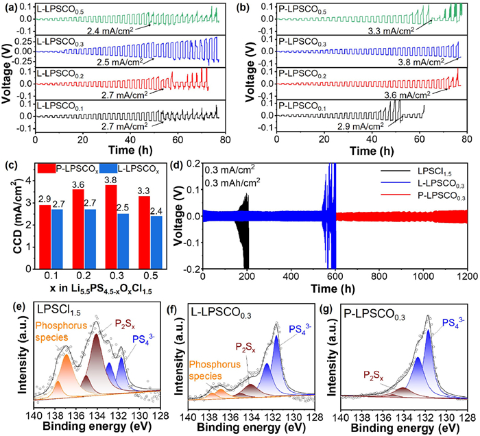
To assess the lithium dendrite inhibition capabilities of various electrolytes, Li/SE/Li symmetric cells were constructed. The galvanostatic tests utilized stepwise increased current densities to determine the critical current densities (CCDs) for different electrolytes. Fig. S9 (Supporting information), Figs. 3a and b illustrate the galvanostatic lithium plating/stripping profiles for cells utilizing LPSCl1.5, L-LPSCOx, and P-LPSCOx (x = 0.1, 0.2, 0.3, and 0.5), respectively. The voltage of all cells increases with rising current density, followed by a marked decrease at a specific threshold, identified as the CCD indicative of lithium dendrite formation [40]. The CCD observed for the LPSCl1.5 electrolyte is 0.7 mA/cm2, while all O-doped electrolytes demonstrate CCDs exceeding 2.5 mA/cm2. For the Li2O-doped electrolytes (L-LPSCOx, x = 0.1, 0.2, 0.3, and 0.5), the CCD values range from 2.4 mA/cm2 to 2.7 mA/cm2 (blue bars in Fig. 3c), suggesting comparable performance across varying O contents. In contrast, the CCD for P2O5-doped electrolytes (P-LPSCOx, x = 0.1, 0.2, 0.3, and 0.5) exhibit a distinct increase with rising O concentration, reaching a maximum of 3.8 mA/cm2 for the P-LPSCO0.3 electrolyte (red bars in Fig. 3c). The lower CCD for P-LPSCO0.5 may be attributed to abundant impurities present in its crystalline structure. The higher CCDs of P2O5-doped electrolytes indicate a superior capacity for suppressing lithium dendrite formation. The cycling performance of Li/SE/Li symmetric cells with LPSCl1.5, L-LPSCO0.3, and P-LPSCO0.3 was evaluated at a current density of 0.3 mA/cm2 (0.3 mAh/cm2). As presented in Fig. 3d, the Li/P-LPSCO0.3/Li cell delivers stable lithium plating/stripping for over 1200 h without short-circuit or failure. The polarization voltage of the Li/P-LPSCO0.3/Li cell remaining below 25 mV even after 1200 h of cycling, indicating a stable interface between lithium metal and the P-LPSCO0.3 electrolyte. Conversely, the voltages for the Li/LPSCl1.5/Li and Li/L-LPSCO0.3/Li cells significantly increase after 140 and 540 h of cycling, respectively, leading to failures within 200 and 600 h. These results highlight the enhanced stability of the O-doped electrolyte, particularly P2O5, in maintaining lithium metal integrity during cycling. The excellent dendrite suppression capability of P2O5-doped electrolytes is attributed to their high densification (Fig. 1i), high phase purity (Figs. 1a and b), and low electronic conductivity (Fig. S10 in Supporting information).
Figure 3
Figure 3.
Galvanostatic Li plating/stripping profiles of Li/SE/Li cells using (a) L-LPSCOx and (b) P-LPSCOx (x = 0.1, 0.2, 0.3, and 0.5) under step-increased current densities. (c) The CCD values of L-LPSCOx and P-LPSCOx (x = 0.1, 0.2, 0.3, and 0.5) electrolytes. (d) Li plating/stripping profiles of Li/LPSCl1.5/Li, Li/L-LPSCO0.3/Li, and Li/P-LPSCO0.3/Li symmetrical cells at 0.3 mA/cm2. The corresponding P 2p XPS spectra of the cycled lithium metal in (e) Li/LPSCl1.5/Li, (f) Li/L-LPSCO0.3/Li, and (g) Li/P-LPSCO0.3/Li cells.
SEM and X-ray photoelectron spectroscopy (XPS) were utilized to analyze the decomposition products on the surface of cycled lithium metal in different cell configurations. Figs. S11a-c (Supporting information) present the SEM images and energy dispersive spectroscopy (EDS) mappings of lithium foils after cycling for 100 h in Li/LPSCl1.5/Li, Li/L-LPSCO0.3/Li, and Li/P-LPSCO0.3/Li cells, respectively. In the Li/LPSCl1.5/Li and Li/L-LPSCO0.3/Li cells, numerous irregular particles are unevenly distributed across the surface of the cycled lithium metal. EDS mappings reveal strong signals for sulfur (S), phosphorus (P), chlorine (Cl), and oxygen (O) (Figs. S11a and b), indicating significant decomposition products from the solid electrolytes (SEs). In contrast, the lithium metal in the Li/P-LPSCO0.3/Li cell exhibits a relatively flat surface with only a few particles and weak signals for S, P, Cl, and O detected (Fig. S11c).
The corresponding P 2p XPS spectra for the cycled lithium metal are illustrated in Figs. 3e-g. Peaks at 131.7 and 132.5 eV (blue) correspond to PS43- from the argyrodite electrolyte (Fig. S12 in Supporting information), while peaks at 134.1 eV (brown) and 136.7 eV (orange) indicate the presence of decomposition products such as P2Sx and various species [12,42]. At the Li/LPSCl1.5 interface, the peaks associated with P2Sx and phosphorus species are predominant, with the electrolyte peaks nearly absent. For the Li/L-LPSCO0.3 interface, peaks from the electrolyte remain dominant, though significant peaks attributed to P2Sx and phosphorus species are still present. Conversely, at the Li/P-LPSCO0.3 interface, the composition of the electrolyte prevails, with only trace amounts of the decomposition product P2Sx detected. Furthermore, the surface of the lithium metal in the recycled Li/P-LPSCO0.3/Li cell maintains a dense and smooth morphology, promoting uniform lithium deposition and preventing the formation of dendrites [40].
Additionally, the SEM images of the SE surfaces from the cycled cells are provided in Fig. S13 (Supporting information). It is evident that both LPSCl1.5 and L-LPSCO0.3 electrolytes exhibit a rough surface, while the P-LPSCO0.3 electrolyte maintains a smooth morphology. This observation indicates that the P2O5-doped electrolyte (P-LPSCO0.3) demonstrates superior electrochemical stability in contact with lithium metal, corroborating the findings from the SEM and XPS analyses of the lithium metal surface.
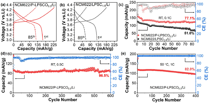
To further evaluate the lithium metal compatibility of P2O5-doped electrolytes, all-solid-state lithium metal batteries (ASSLMBs) were constructed using LiNi0.6Co0.2Mn0.2O2 (NCM622) coupled with P-LPSCO0.3 and LPSCl1.5 electrolytes. The electrochemical performances of these batteries are illustrated in Fig. 4 and Fig. S14 (Supporting information). As depicted in Fig. 4a, the ASSLMB incorporating P-LPSCO0.3 exhibits an initial discharge specific capacity of 163.3 mAh/g at a rate of 0.1 C at r.t. After 85 cycles, the discharge capacity remains at 125.9 mAh/g, reflecting a capacity retention of 77.1% (Fig. 4c). In contrast, the ASSLMB utilizing LPSCl1.5 registers an initial discharge specific capacity of 126.7 mAh/g, with a reduced capacity retention of 51.0% after the same cycling period (Figs. 4b and c). The charge/discharge curves of both batteries at the first and 85th cycles illustrate that the ASSLMB with P-LPSCO0.3 maintains lower polarization throughout the cycling process.
Figure 4
Figure 4.
The initial and 85th charge/discharge curves of the (a) NCM622/P-LPSCO0.3/Li and (b) NCM622/LPSCl1.5/Li ASSBs, (c) the corresponding cycling performances at 0.1 C under r.t. Cycling performance of NCM622/P-LPSCO0.3/Li ASSB (d) at 0.5 C under RT and (e) at 1.0 C under 50 ℃.
EIS measurements performed before and after cycling reveal that the ASSLMB with LPSCl1.5 displays significantly higher interfacial impedance compared to that with P-LPSCO0.3 after 85 cycles (2100 Ω vs. 1000 Ω, Figs. S14a and b). The increased interfacial impedance indicates greater side reactions occurring between lithium metal and the solid electrolyte (SE) [8]. Furthermore, the rate performances presented in Fig. S14c reveal that the NCM622/P-LPSCO0.3/Li battery achieves discharge capacities of 165.4, 132.6, 86.1, 60.2, and 46.7 mAh/g at varying C-rates of 0.1, 0.2, 0.5, 0.8, and 1.0 C, respectively. The battery with P-LPSCO0.3 also demonstrates smaller polarization voltages compared to that with LPSCl1.5 under different C-rates (Figs. S14d and e).
To further assess the lithium metal stability of the P-LPSCO0.3 electrolyte under challenging conditions, the NCM622/P-LPSCO0.3/Li ASSLMB was evaluated under r.t. at 0.5 C and under 50 ℃ at 1 C. As shown in Fig. 4d, at r.t. under 0.5 C, after activating at 0.1 C for 2 cycles, the battery delivers a discharge capacity of 92.4 mAh/g and retains 89.2 mAh/g after 600 cycles, resulting in a remarkable capacity retention of 96.5%. At 50 ℃ under 1 C, the battery achieves a high initial discharge capacity of 136.0 mAh/g, with a capacity retention of 82.0% after 400 cycles (Fig. 4e). These findings highlight the outstanding cycle stability of the NCM622/P-LPSCO0.3/Li battery under stringent conditions, underscoring the exceptional lithium metal stability of the P-LPSCO0.3 electrolyte. The results indicate that P2O5-doped electrolytes hold significant promise for application in ASSLMBs.
In conclusion, we synthesized O-doped Li5.5PS4.5Cl1.5 (LPSCl1.5) electrolytes using Li2O and P2O5 as oxygen sources and systematically investigated their effects on the structure, air stability, and lithium compatibility of sulfide electrolyte. For P2O5-doped electrolytes, O replaces more S at the 16e site, resulting in better air stability due to the reduced unstable P-S bond. Notably, P-LPSCO0.3 retains a higher ionic conductivity (2.7 mS/cm) than L-LPSCO0.3 electrolyte (2.4 mS/cm) after air exposure. XRD refinement and SEM analyses reveal that P2O5-doped electrolytes (P-LPSCOx) exhibit purer phase, larger cell parameter, and denser pellets, leading to improved ionic conductivity and enhanced suppression ability of lithium dendrite. P-LPSCO0.3 achieve a CCD of 3.8 mA/cm2 compared to 2.7 mA/cm2 for Li2O-doped electrolytes and 0.7 mA/cm2 for LPSCl1.5. Additionally, the P2O5-doped electrolytes demonstrate superior lithium compatibility, with the Li/P-LPSCO0.3/Li symmetric cell maintaining stable cycling for over 1200 h at 0.3 mA/cm2. The NCM622/P-LPSCO0.3/Li full cells retaining 96.5% capacity after 600 cycles at r.t. (0.5 C) and 82.0% after 400 cycles at 50 ℃ (1.0 C). This study offers valuable insights into the selection of raw materials for modifying sulfide solid electrolytes and guides the choice of oxygen sources for oxygen-doped systems.
The authors declare that they have no known competing financial interests or personal relationships that could have appeared to influence the work reported in this paper.
This work was supported by the National Natural Science Foundation of China (No. 52377208). We gratefully acknowledge the Analytical and Testing Center of HUST, and Shiyanjia Lab (www. shiyanjia.com) for allowing us to use its facilities.
Supplementary materials
Supplementary material associated with this article can be found, in the online version, at doi:10.1016/j.cclet.2025.111015.
[1]
K. Kim, M. Balaish, M. Wadaguchi, L. Kong, J. Rupp, Adv. Energy Mater. 11 (2021) 2002689. doi: 10.1002/aenm.202002689
[2]
H. Yuan, J. Liu, Y. Lu, et al., Chem. Res. Chin. U. 36 (2020) 377–385. doi: 10.1007/s40242-020-0103-5
Y. Nikodimos, S.K. Jiang, S.J. Huang, et al., ACS Energy Lett. 9 (2024) 1844–1852. doi: 10.1021/acsenergylett.4c00500
[42]
J. Auvergniot, A. Cassel, D. Foix, et al., Solid State Ionics 300 (2017) 78–85.
Figure 1
XRD patterns of Li5.5PS4.5-xOx Cl1.5 (x = 0.1, 0.2, 0.3, and 0.5) electrolytes with (a) Li2O and (b) P2O5 as oxygen source. Results from XRD Rietveld refinement: (c) Percentage content of impurities in the prepared electrolyte structures, oxygen content at 4d and 16e sites in (d) Li2O and (e) P2O5 doping electrolytes. (f) Ionic conductivity values of the above SEs. SEM images of the pelleted (g) LPSCl1.5, (h) L-LPSCO0.3, and (i) P-LPSCO0.3 electrolytes.
Figure 2
(a) XRD patterns and (b) ionic conductivities of LPSCl1.5, L-LPSCO0.3, and P-LPSCO0.3 electrolytes after exposing to air for 20 min. With humidity of 40%. (c) Schematic diagram of crystal structure and oxygen doping modification of Li5.5PS4.2O0.3Cl1.5 electrolyte.
Figure 3
Galvanostatic Li plating/stripping profiles of Li/SE/Li cells using (a) L-LPSCOx and (b) P-LPSCOx (x = 0.1, 0.2, 0.3, and 0.5) under step-increased current densities. (c) The CCD values of L-LPSCOx and P-LPSCOx (x = 0.1, 0.2, 0.3, and 0.5) electrolytes. (d) Li plating/stripping profiles of Li/LPSCl1.5/Li, Li/L-LPSCO0.3/Li, and Li/P-LPSCO0.3/Li symmetrical cells at 0.3 mA/cm2. The corresponding P 2p XPS spectra of the cycled lithium metal in (e) Li/LPSCl1.5/Li, (f) Li/L-LPSCO0.3/Li, and (g) Li/P-LPSCO0.3/Li cells.
Figure 4
The initial and 85th charge/discharge curves of the (a) NCM622/P-LPSCO0.3/Li and (b) NCM622/LPSCl1.5/Li ASSBs, (c) the corresponding cycling performances at 0.1 C under r.t. Cycling performance of NCM622/P-LPSCO0.3/Li ASSB (d) at 0.5 C under RT and (e) at 1.0 C under 50 ℃.

 DownLoad:


 下载:
下载:


 下载:
下载:
