Scheme 1.
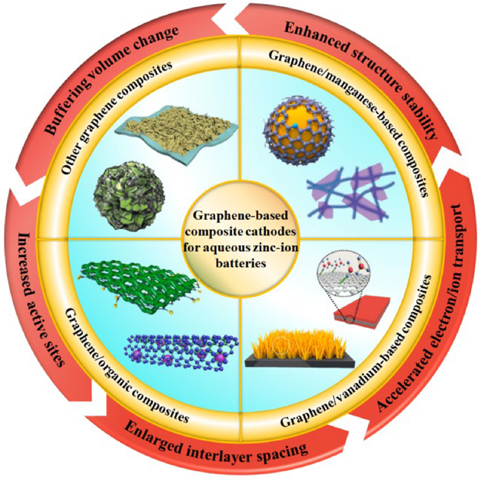
The application of graphene-based composites as the cathode of AZIBs.
Graphene-based composites as the cathodes for high-performance aqueous zinc-ion batteries: Applications and perspectives
Yifei Pei , Yong Liu , Chunyang Kong , Zhihui Jia , Kaijia Feng , Yibo Xing , Mingliang He , Xiujie Gao , Ruxia Liu , Xianming Liu , Kunming Pan , Qiaobao Zhang

In the past few centuries, fossil energy has been the dominant energy on the earth [1,2]. With the rapid development of modern industry, science, and technology, the exploitation and utilization of fossil fuels led to severe issues, including global warming and environmental pollution [3–5]. It has prompted people to focus on the development of economic, environmentally friendly, and renewable energy technologies to meet society's growing need for energy [6–8]. In this regard, renewable energy sources such as solar, tidal, and wind energy have garnered widespread attention recently [9–11]. Whereas, the volatility, intermittency, and uneven distribution during their usage have hindered their practical application, leading to significant energy wastage [12–15]. In light of these issues, electrochemical energy storge (EES) devices have been recently considered as an effective way to solve the existing problems of renewable energy sources [16–22]. Among the EES devices, aqueous zinc ion batteries (AZIBs) have been developed and considered a promising storage energy systems because of their low-cost, long cycling life, excellent rate performance and flexibility [23–28].
AZIBs are composed of cathode, anode, electrolyte, and separator. Among them, the cathode materials are crucial for the electrochemical performance of AZIBs. In recent years, more and more cathode materials for AZIBs have been reported, such as manganese-based materials [29], vanadium-based materials [29,30], organic materials [31], and others. However, their applications are limited owing to the low electrical conductivity and poor structural stability. For example, the relatively low electronic and ionic conductivity of pure V2O5 leads to unsatisfactory battery performance [32]. Therefore, more and more attention has been paid to the design and synthesis of advanced composite materials, which is crucial to improve the electrochemical properties of AZIBs. In the 21st century, the research of graphene-based composites has received extensive attention due to its outstanding electrical conductivity and mechanical strength [33–36]. Specially, the fabrication of graphene-based composites has been developed in an effort to broaden the development of AZIBs, which can buffer volume change and provide more electron transport pathways to accelerate the reaction kinetics [37,38]. To date, most of contributions have focused on the application of graphene-based composite materials for the cathode of AZIBs [39–41]. For example, Yi et al. [37] successfully fabricated a ZnTe/rGO composite as a new conversion-type cathode for AZIBs, and the composites exhibited an exceptional capacity of 186 mAh/g at 500 mA/g over 300 cycles, which resulted from the solid-to-solid type of conversion, the ability to alleviative the change in volume of ZnTe, and the good conductivity of the graphene matrix. Moreover, Wang et al. [38] designed porous rGO-boosted amorphous manganese oxides microspheres (named PrGO–MnOx) as a novel cathode for AZIBs. The assembled PrGO–MnOx||AQ (9,10-anthraquinone) full-cell manifested a capacity of 305 mAh/g at 0.1 A/g and an excellent capacity of 106 mAh/g over 500 cycles at 0.3 A/g. Furthermore, some reviews have discussed the advances of graphene-based materials in AZIBs. For instance, Bi et al. reviewed the progress of two-dimensional materials including graphene for AZIBs, especially in cathodes and anodes [42]. Recently, Lu and co-workers summarized the application of graphene and other carbon materials on the anode of AZIBs [43]. Although some reviews on the progress of graphene materials have been proposed, to the best of our knowledge, a comprehensive review that systematically focuses on graphene-based materials as the cathode for AZIBs was rarely reported, especially in the aspect of the structure and properties, applications as well as prospects for the future.
This review mainly summarizes the recent developments and applications of graphene on the cathode of AZIBs, including their methods of preparation and the electrochemical properties of graphene/manganese-based, graphene/vanadium-based, graphene/organic materials, and other graphene composites (Scheme 1). Moreover, the challenges and strategies of cathodes for AZIBs as well as the structure and properties of graphene-based composite materials are introduced. Furthermore, we expound the representative improvements of graphene-based materials, in which their manufacturing methods, nano- and microstructures, as well as the effect on the electrochemical performance are systematically discussed. Additionally, some potential challenges, rational suggestions, and prospects for their future development are proposed. Hopefully, this review will attract more intention in the application of graphene-based composites as the cathode in AZIBs and boost their practical applications.
Up to date, considerable efforts have been exerted to explore suitable and excellent cathode for AZIBs, which can be broadly classified into Mn-based materials, V-based materials, organic materials and others. Nevertheless, there remain accompanying limitations that impede their development and application.
Due to the high charge density of Zn2+, it can produce strong electrostatic interactions directly with the host material. The strong electrostatic interaction between Zn2+ and cathode host materials leads to the expansion of layer spacing, the rapid bending vibration of skeleton, and finally causing the collapse of the structure. Moreover, it gives rise to the difficulty in the diffusion and insertion/extraction of Zn2+ [44–47].
The dissolution of manganese and vanadium is common in the dissolution of cathode materials, which causes the decrease in capacity and deterioration of battery performance [47,48]. Manganese dissolution occurs mostly in the process of disproportionation reactions and structural transformation during cycling [49]. Similarly, in weakly acidic aqueous solution of ZnSO4 and Zn(CF3SO3)2, the cycling process may produce vanadium-related ions that are soluble in the electrolyte, resulting in the vanadium dissolution [50].
Zinc hydroxide sulfate (Zn4(SO4)(OH)6·nH2O, ZHS) is a by-product that may occur during the cycle [47]. It is an alkaline zinc salt that tends to form in alkaline environments. The formation of ZHS could stem from the increase in pH at the interface between the electrolyte and the electrode during the discharging process, which facilitates the generation of ZHS. If it accumulates gradually during the continuous cycling process, it will undoubtedly lead to the continuous consumption of the aqueous electrolyte, blocking the path of ion transport and resulting in an increase in electrochemical impedance [51,52].
Considering the challenges mentioned above, some novel strategies have been proposed and applied to optimize the cathode of AZIBs, including pre-intercalated method, surface coating, defect engineering, morphology design and fabrication of composite materials (Fig. 1) [48,53,54].
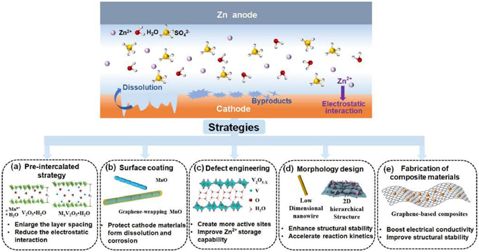
The pre-intercalated strategy is an effective way to enlarge the layer spacing and reduce the electrostatic interaction between Zn2+ and the host cathode. For example, Wang and co-workers [55] intercalated polyaniline into MnO2 to obtain polymer-reinforced layered structure, which is beneficial for improving its electrochemical performance. In addition to organic molecules, the pre-intercalated species may also include alkali metal cations (Na+, K+), alkali earth metal cations (Mg2+, Ca2+), transition metal cations (Cu2+, Ag+) and other cations NH4+ [56].
Moreover, using carbon materials or conductive polymer coating are conductive to protect cathode materials form dissolution and corrosion. For example, Wu et al. [57] employed graphene to coat on MnO2 nanowires, which serves as an effective way to inhibit the dissolution of manganese.
Defect engineering has shown significant positive impacts in the research of cathode materials. The introduction of defects (such as oxygen vacancy and heteroatom doping) in cathode materials can create more active sites, improve the Zn2+ storage capability, as well as promote capacity and reversibility of materials [48,58].
The morphology design engineering has been reported by Han and colleagues [54], including low-dimensional, hierarchical and hollow structures. The structures enable the cathode materials to have a high surface to mass/volume ratio excellent conductivity, numerous active sites, and a stable framework structure, which can adapt to the expansion in volume during cycling process. Therefore, the morphology design engineering enhances structural stability, reaction kinetics and capacity of cathode materials under the without changing the overall redox reaction.
The fabrication of composite materials is regarded as one of the prevalent approaches to enhance the properties of cathode materials. For the low electrical conductivity of organic materials, it is combined with conductive substances like graphene, which not only boosts the overall electrical conductivity of the material but also enhances the structural stability.
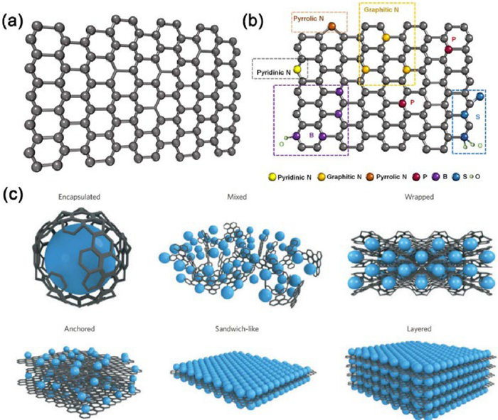
Since graphene was first exfoliated from bulk graphite in 2004, it has attracted extensive attention due to its unique structure and excellent physicochemical properties [59–61]. Graphene possesses a highly symmetrical single-layer hexagonal honeycomb structure and was recognized as the first two-dimensional (2D) atomic crystal (Fig. 2a) [59]. Graphene's internal carbon atoms form bonds through sp2 hybrid orbitals, with each carbon atom having four valence electrons. The three electrons form sp2 bonds, meaning each carbon atom contributes one unpaired electron located on the pz orbital. The pz orbitals of the neighboring carbon atoms can form π bonds in a direction perpendicular to the plane [59,62]. Therefore, graphene's unique structure gives it several excellent physical and chemical characteristics. First, the π electrons originating from the pz orbitals can move freely in the plane, giving graphene superior electrical and thermal properties. Second, graphene exhibits a stable structure, a strong interatomic force, and less interference with electronic motion, resulting in superior physical and chemical properties [63–65]. These physical and chemical properties include high electronic conductivity, a large theoretical specific surface area (≈2630 m2/g) [66], great tensile strength (130 GPa) [67], excellent thermal conductivity (5000 W m−1 K−1) [68], as well as fast carrier mobility (>105 cm2 V−1 s−1) [59,69]. In addition, graphene's derivatives are rich in functional oxygen groups, such as GO and rGO, which can be utilized as substrates to compound with various organic and/or inorganic materials [70], providing an opportunity to construct graphene-based composites.
Nevertheless, the development and application of graphene-based composite materials is hindered by certain problems. Firstly, the van der Waals forces between nanosheets of graphene will inevitably led to the aggregation or accumulation of graphene during their preparation process and during the electrochemical reaction, reducing its electrochemical performance [60]. Secondly, the defect and active sites on the surface of graphene are few in number, meaning that it is difficult for graphene to interact with some substances under normal conditions [61]. Thirdly, the packing density of graphene is low (0.015 g/cm3), which results in a low energy density and volumetric capacitance, limiting its application in high-energy EES devices [60]. Fourthly, the zero-band gap of graphene limits the effective regulation of its conductivity [63]. In light of the aforementioned issues, researchers have employed heteroatom doping [71], and synthesis of graphene-based composites to regulate the properties of graphene and broaden its applications.
With heteroatomic doping, electrons or holes can be injected into graphene to customize the electronic structure of graphene [71–73]. A schematic illustration of graphene doped with various heteroatoms (N, S, B, P) is shown in Fig. 2b. The N atoms are regarded as the optimal heteroatom for improving the conductivity of graphene, mainly because electrons can be transferred from the highly electronegative N atoms to the neighboring C atoms [74]. This leads to a redistribution of charge density within the graphene plane, thus greatly enhancing its conductivity. In addition, the incorporation of N atoms effectively reduce the agglomeration between graphene sheets, significantly increase the specific surface area of the electrode material and provide more active sites as well as greatly accelerate the transport of ions [75]. Furthermore, doping B atoms into graphene introduces defects on the exposed nanosheets of graphene, and C atoms modulate the electron donors and acceptors, thus improving the electrochemical performance [76]. Furthermore, doping other atoms (S, P, etc.) or heteroatom co-doping can also endow graphene with outstanding properties [59].
Compared with pure graphene, researchers have found that graphene-based composites generally have superior performance because of the synergy of different components [61]. Graphene-based composite electrode materials with different structures are shown in Fig. 2c. The formation of graphene composites buffers the change in the volume of the composite materials and avoids the restacking of the graphene nanosheets [77]. Moreover, graphene demonstrates considerable electron mobility in nanocomposites. It serves as an outstanding electron acceptor, significantly enhancing the transfer rate of electron and/or ions. Furthermore, the formation of a multitude of voids and channels within the graphene-based composites greatly increase their specific surface area and the number of active sites, thus accelerating the electrochemical kinetics of the battery. In summary, the strong synergy between the highly conductive graphene and the other components endows it with exceptional electrochemical properties [61,77].
To date, manganese-based materials are widely utilized as positive electrodes for AZIBs because of their low cost and environmentally friendly features [29,78]. Moreover, the multiple valence states of Mn and the variety in its crystal structures further expand the application prospects of manganese-based materials [29,79]. Nevertheless, the low electrical conductivity and change in volume during the phase transition process have resulted in poor performances [25]. To address the issues, manganese-based materials were combined with conductive graphene to significantly enhance their electrochemical performance. In this section, graphene/manganese oxides (MnxOy), graphene/zinc manganate, and graphene/others have been investigated as mainly cathode materials for AZIBs [25,79].
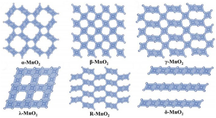
Graphene/MnO2 composites: Manganese dioxide (MnO2) has been widely concerned owing to its environmentally friendly properties, decent theoretical capacity and considerable theoretical voltage [80]. However, using MnO2 as cathode material still has many issues, such as the rapid diffusion of Mn2+, poor mechanical properties, low electrical conductivity, and the sluggish transport kinetics driven by the strong electrostatic interactions between the host materials and Zn2+ [81–83]. Recently, previous studies found that graphene/MnO2 composites effectively improved the performance of AZIBs. Meanwhile, according to previous reports, MnO2 possesses diverse polymorphs, and the variety of its crystal structures significantly affect the storage of Zn2+ [79,84,85], including α-MnO2 [57,83,86–96], β-MnO2 [97,98], γ-MnO2 [99], δ-MnO2 [100–102]. The MnO6 octahedron serves as the fundamental unit in the way of sharing the angles or edges to construct different structures [84,103]. The various crystal structures of MnO2 are displayed in Fig. 3.
Among the diverse polymorphs of MnO2, the use of α-MnO2 in AZIBs has been reported widely. This can be attributed to their excellent ability to facilitate fast and reversible storage of Zn ions [29]. For instance, in order to design flexible and foldable AZIBs, Wang et al. [89] successfully prepared a freestanding and lightweight MnO2/rGO membrane via a simple vacuum filtration technique. Fig. 4a shows that the close contact between the rGO nanosheets and the MnO2 nanowires. As a result, the MnO2/rGO as cathode exhibited excellent cycling stability with a low fading rate of 0.011% per cycle over 2000 cycles at 2.0 A/g (Fig. 4b). Furthermore, Wu et al. [57] synthesized a α-MnO2/graphene scrolls (MGS) by a simple hydrothermal method. The graphene scrolls were uniformly coated on the MnO2 nanowires, as shown in Fig. 4c, which increased the electrical conductivity of the MnO2 nanowires and inhibited the dissolution of the cathode materials during cycling. Additionally, the cathode made from α-MnO2/graphene scrolls exhibited excellent specific capacities (Fig. 4d). As a result, it also maintained a capacity of 87.4 mAh/g after 800 cycles at 7 A/g and obtained a high capacity of 145.3 mAh/g over 3000 cycles at 3 A/g with a retention ratio of 94% (Fig. 4e). Regarding the composite material of α-MnO2/rGO, it is worth noting that conductive additives are commonly used to enhance the performance of the original electrode material [83,92,95]. For instance, Niu et al. [92] successfully prepared a-MnO2/rGO-PPy composite through coating conductive polypyrrole (PPy) on α-MnO2/rGO nanowires, which significantly improved the electrochemical performance of α-MnO2/rGO cathode. Furthermore, Chen et al. [95] recently prepared a 3D MnO2–vertical graphene composite with a conductive network of poly(3,4-ethylenedioxythiophene)–poly(styrene sulfonate), referred to as VMP. As shown in Fig. 4f, the image indicates that the conductive polymer (poly(3,4-ethylenedioxythiophene)–poly (styrene sulfonate)) was uniformly coated on the vertical graphene–MnO2 electrode, thus reducing the dissolution of Mn during cycling and reinforcing the nanostructure of vertical graphene–MnO2. Meanwhile, the VMP cathode for AZIBs displayed excellent rate capacities (Fig. 4g) and long-term cycling capacity of 73.7% retention was achieved over 1000 cycles at 5 A/g (Fig. 4h). The exceptional electrochemical behaviors could be attributed to the unique advantages of the 3D structured VMP created by embedding vertical graphene nanosheets into MnO2, which effectively enhances charge transfer kinetics, zinc ion storage capability, and mechanical durability of VMP composites.
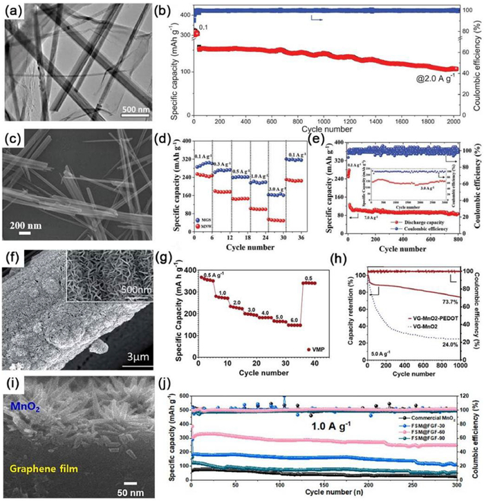
Furthermore, considerable efforts have been devoted to investigate graphene films as current collectors to construct graphene/MnO2 composites because of their good flexibility, high electrical conductivity, and excellent mechanical properties. Lee et al. [88] reported that free-standing MnO2 on a flexible graphene film (FSM@FGF) was produced as a novel and superior cathode by a selective growth process. As shown schematically in Fig. 4i, the cross-sectional image of the FSM@FGF-60 (FSM@FGF obtained at 60 ℃) clearly shows that the MnO2 was uniformly anchored and dispersed on the flexible graphene film's surface, contributing to the overall specific capacity and stable cyclic performance at high current density. As a result, the fabricated FSM@FGF-60 cathode material exhibited an 82.7% capacity retention over 300 cycles at 1 A/g (Fig. 4j), which can be attributed to the accelerated charge transfer process resulting from the use of a binder-free electrode, as well as the improved diffusion ability of zinc ions caused by the uniform distribution of free-standing MnO2 on the surface of graphene.
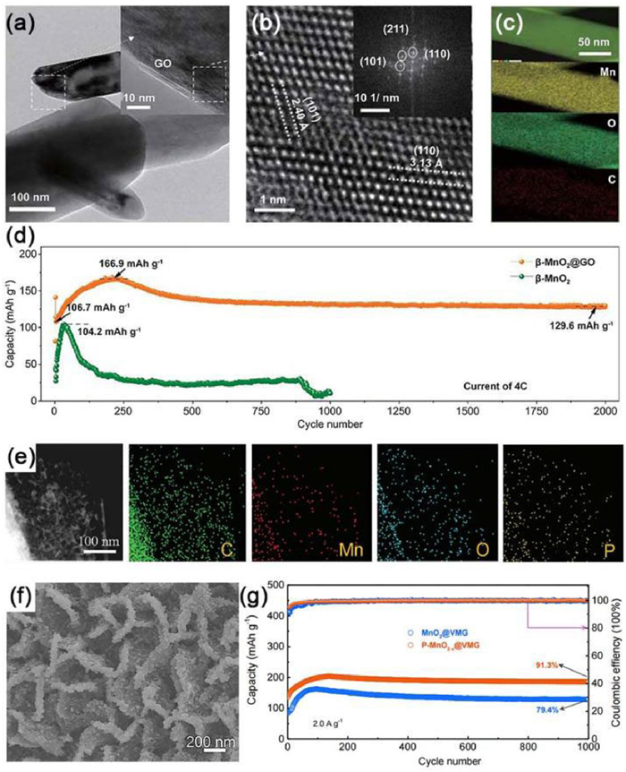
In addition to α-MnO2, other crystalline phases of MnO2 (e.g., β, δ, γ, ε and ramsdellite-MnO2) have also demonstrated with good storage of zinc ions. For instance, Ding et al. [98] obtained an oxygen–deficient β–MnO2@GO cathode via a typical hydrothermal method. The TEM image of β–MnO2@GO showed that the successful wrapping of GO onto MnO2, which inhibited the dissolution manganese ions (Fig. 5a). Besides, the lattice fringes of the (101) and (110) planes correspond to β-MnO2@GO (Fig. 5b). Fig. 5c shows that the Mn, O, and C elements were evenly distributed. Consequently, benefiting from defect engineering and interfacial optimization, the rate capability and cycling stability of MnO2 cathodes were effectively improved. As a result, the battery with a β-MnO2@GO electrode obtained a reversible capacity of ~129.6 mAh/g after up to 2000 cycles at 4 C (Fig. 5d). Moreover, δ-MnO2 can effectively avoid the tunnel-to-layer phase transition, which is beneficial for keeping the structure stable. Zhang et al. [100] introduced oxygen defects into phosphate-embedded MnO2 and composited it with vertical multilayered graphene (VMG) to obtain a P-MnO2-x@VMG cathode via a facile phosphorization process. Fig. 5e reveals the homogeneous distribution of C, Mn, O, and P elements. Moreover, the resulting composite displayed a thick and rough surface (Fig. 5f). When tested as cathodic materials for AZIBs, the P-MnO2-x@VMG composites showed superb long-term cycling stability of more than 90% capacity retention over 1000 cycles at 2.0 A/g (Fig. 5g). The outstanding electrochemical performance could be ascribed to the introduction of oxygen defects and intercalation of phosphate ions into δ-MnO2, allowing excellent electrical conductivity and enlarged interlayer spacing. In addition, it has been reported that γ-MnO2 is composed of randomly arranged 1 × 1 (size: ~ 2.3 Å × 2.3 Å) and 1 × 2 (size: ~ 2.3 Å × 4.6 Å) tunnels, which are conductive to beneficial the intercalation and deintercalation of zinc ion [79,104]. For example, Lu's group [99] recently constructed a MnO2 nanorods/graphene composite as a cathode via a scalable hydrothermal method, which notably enhanced the electrochemical properties of AZIBs. Similarly, ramsdellite-MnO2 [105] has also been applied in a graphene/MnO2 composite. For example, Wu et al. [105] synthesized a flexible MnO2/GO composite hydrogel material by a repeated–freeze thaw approach, which was composed of a polyvinyl alcohol hydrogel, MnO2, and graphene. The synthesized cathode with a 3D cross-linking system exhibited a high capacity of 164.2 mAh/g at 1 A/g and superb cycling stability over 500 cycles at 1 A/g.
Other graphene/manganese oxide composites: Other graphene/manganese oxide composites have also been fabricated and considered as promising cathode materials for AZIBs, including graphene/MnO [40,106–111], graphene/Mn2O3 [112], graphene/Mn3O4 [113] and graphene/Mn5O8 [114].
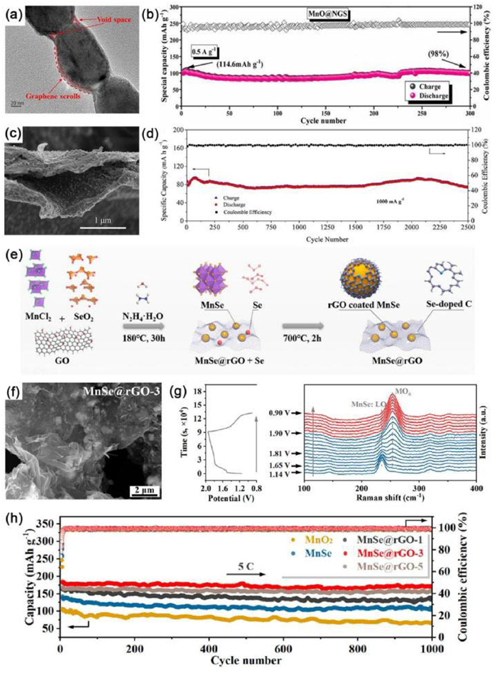
For instance, to extensively improve the electrochemical properties of graphene/MnO composites, researchers have recently conducted a significant amount of work. For instance, Li et al. [40] reported a core–sheath MnO@N-doped graphene scroll (MnO@NGS) configuration by a modified hydrothermal method. Meanwhile, multiple layers of graphene films were coated on the surface of MnO nanochains, forming core–sheath nanostructures and blank regions (Fig. 6a). Consequently, when tested as cathode for AZIBs at 0.5 A/g, the MnO@NGS composite delivered an improved capacity retention of 98% over 300 cycles (Fig. 6b). Furthermore, Liu et al. [110] successfully constructed composites from MnO-pillared graphene blocks (G-MnO). Graphene, serving as the conductive network and spatial confinement layer of MnO, effectively mitigated the variation in volume before and after the deposition of MnO, and ultimately enhanced the cyclic reversibility. With the help of the MnO-pillared graphene block cathode, it manifested excellent rate capability and the as-fabricated battery showed that 93 mAh/g remained after 5000 cycles at 10 A/g.
Apart from MnO, other graphene/manganese oxide composites, such as Mn2O3 [112], Mn3O4 [113] and Mn5O8 [114] have also been combined with graphene as cathodes for AZIBs. For example, Zhou et al. [112] fabricated a unique 2D hierarchical structure of Mn2O3@graphene through growing Mn2O3 nanosheets vertically on the surface of thin layers of graphene. This hierarchical Mn2O3@graphene positive electrode demonstrated great cyclability of 125 mAh/g after 5000 cycles at 7 A/g. Huang et al. [113] demonstrated that the as-prepared Mn3O4/GO at low temperatures formed well-defined nanoscale crystals, and overcame the poor electrochemical performance of pure Mn3O4. When utilized Mn3O4/GO as cathodic materials for AZIBs, an excellent discharge capacity (215.6 mAh/g at 0.1 A/g) and great cyclability (85.0% capacity retention rate over 500 cycles at 1 A/g) were obtained. Furthermore, Sun et al. [114] prepared a Mn5O8–graphene hybrid composite to be used as a cathode for AZIBs, which delivered a high reversible capacity of 260 mAh/g at 100 mA/g and showed excellent long-term cycling stability of 98.8% capacity retention over 1000 cycles.
Due to the advantages of their high voltage platform, abundant raw materials, low cost, and non-toxic and environmentally friendly characteristic, zinc manganese has received considerable attention recently [115–120]. For example, Fan et al. [116] synthesized an advanced composite material comprising GO-wrapped ZnMnO3 nanorod (ZMO/GO) by a coprecipitation method. Benefiting from the high electrical conductivity and "buffer layer" effect contributed by the GO coating, the prepared battery using GO-wrapped ZnMnO3 as cathode exhibited a remarkable specific capacity of 174.8 mAh/g at 0.1 A/g. Furthermore, Yang's group [115] reported a ZnMn2O4/N-doped graphene nanocomposite (ZnMn2O4/NG) prepared via a facile one-step hydrothermal approach. The SEM images clearly showed that a typical lamellar sandwich structure, with ZnMn2O4 nanoparticles evenly distributed on both sides of the NG sheets (Fig. 6c). When investigated ZnMn2O4/NG nanocomposite as cathode for AZIBs, a superb cycling life with 97.4% capacity retention over 2500 cycles at 1 A/g was obtained (Fig. 6d). The excellent performance was ascribed to the synergistic effect between ZnMn2O4 nanoparticles, which facilitated rapid capacitive reactions on the surface and short electron or ion transport pathways, as well as the highly conductive NG, which accelerated electron transport and stabilized the composite structure during the charge and discharge process.
In addition to the aforementioned composites, other graphene/manganese-based composites will also be briefly discussed for AZIBs, such as MnSe@rGO [121], MnS/rGO [122], C@MnSe@GO-x [123] and potassium-doped manganese dioxide (KMO) carbon nanotubes (CNT) plus graphene [124]. For example, Ma et al. [122] fabricated a composite material of MnS/rGO as the electrode in AZIBs with decent the electrochemical results. In addition, because the electronic conductivity of MnSe was better than that of MnS, Wang et al. [121] synthesized MnSe@rGO composites by a hydrothermal method (Fig. 6e). As illustrated in Fig. 6f, the SEM image of MnSe@rGO-3 (obtained by using a 13% mass ratio of GO/(MnCl2·4H2O+SeO2)) showed that the introduction of GO led to no pores and smaller MnSe particles. As shown in Fig. 6g, it revealed the structural evolution of the LO to MO6 mode during the initial activation of MnSe@rGO. Furthermore, researchers used X-ray diffraction (XRD) patterns to reveal phase transition of MnSe to α-MnO2. Benefiting from abundant active sites of MnO2, the MnSe@rGO-3 electrode exhibited superb cycling performance (Fig. 6h). The improved performance could be ascribed to the advantages of rGO, which inhibited the structural failure and facilitated the phase transition of MnSe. In addition, Li's groups [124] successfully prepared a novel composite of KMO mixed with CNTs and graphene (called hydrated KMO—CNT/graphene) through the polyol reduction approach. The intercalation of H2O and doped K effectively avoided the collapse of the MO's structure, and the CNTs and graphene enhanced the electrical conductivity. Consequently, the KMO—CNT/graphene electrode demonstrated favorable electrochemical properties.
Manganese-based composites (such as MnO2, MnO, ZnMn2O4) have been extensively applied to AZIBs and shown suitable electrochemical performance as cathode materials (Table 1). Nevertheless, the poor electrical conductivity, the dissolution of Mn2+, severe structural deterioration, and change in volume of manganese-based materials during the phase transition process mainly limit their further development. To address the issues, researchers have concentrated on combining them with conductive graphene and its derivatives (GO and rGO) owing to their admirable electrical conductivity and mechanical properties. The introduction of graphene significantly suppresses the dissolution of Mn and strengthens structural stability of the composites. Typically, defect engineer and heteroatom doping are employed to further increase active sites and improve electrical conductivity. With different manufacturing methods and modification strategies, the as-fabricated graphene/manganese-based composites manifest more satisfactory electrochemical performances than pure manganese-based composites. Hopefully, further in-depth investigations into graphene/manganese-based composites for AZIBs will overcome these limitations.
 DownLoad:
CSV
DownLoad:
CSV
| Materials | Synthesis method | Current density (A/g) |
Cycle number | Capacity retention ratio (%) | Specific capacity (mAh/g, mA/g) |
Refs. |
| Graphene/manganese-based composites | ||||||
| MnO@NGS | Hydrothermal and calcination | 0.5 | 300 | 98 | 288, 100 | [40] |
| MGS | Hydrothermal | 3 | 3000 | 94 | 382.2, 300 | [57] |
| MnO2/NGA | – | 3 | 1000 | 93.6 | 275.8, 100 | [86] |
| MnO2/rGO | Vacuum filtration | 6 | 500 | 96 | 332.2, 300 | [87] |
| FSM@FGF-60 | – | 1 | 300 | 82.7 | 440.1, 100 | [88] |
| MnO2/rGO | Vacuum filtration | 2 | 2000 | – | 317, 100 | [89] |
| UFMP@IQGF | – | 2 | 300 | 83.7 | 404.7, 100 | [90] |
| MnO2–40GQD | Hydrothermal | 0.1 | 100 | 88.99 | 295.7, 100 | [91] |
| α-MnO2/rGO-PPy | Hydrothermal and in situ polymerization | 0.5 | 100 | 85.9 | 248.8, 500 | [92] |
| 20-MnO2@graphene | Electrochemical deposition | 4 | 2000 | 86.4 | 363.6, 500 | [93] |
| 3D MNWs@GNSs | Gas phase spray drying | 2 | 10,000 | 97.5 | 306.8, 100 | [94] |
| VMP | Plasma enhanced chemical vapor deposition/hydrothermal/dip-coating | 5 | 1000 | 73.7 | 367.4, 500 | [95] |
| MnO2/rGO | – | 0.3 | 300 | 78.68 | 164, 50 | [96] |
| Ni-MnO2/Graphene | Hydrothermal and mechanical ball milling | 2 | 2200 | 56 | 431.5, 100 | [97] |
| β-MnO2@GO | Hydrothermal | 4 C | 2000 | 121.4 | 312.4, 77 | [98] |
| γ-MnO2-graphene | Hydrothermal | 10 | 300 | 64.1 | 301, 500 | [99] |
| P-MnO2-x@VMG | Hydrothermal and phosphorization | 2 | 1000 | >90 | 302.8, 500 | [100] |
| MnO2 NDs/rGO | Hydrothermal and ultrasonic treatment | 1 | 1000 | 90.1 | 294, 100 | [101] |
| GQDs@ZnxMnO2 | – | 1 | 500 | 88.1 | 403.6, 300 | [102] |
| HG MnO2/GO | Repeated freeze-thaw | 1 | 500 | – | 164.2, 1000 | [105] |
| MPGC | Hydrothermal and solid thermal reduction | 0.5 | 200 | 96.2 | 267.4, 200 | [106] |
| MnO/C@rGO | Solvothermal | 0.5 | 300 | – | 110.1, 2000 | [107] |
| A-MnO/G | Static oxidation of flake graphite | 3 | 2000 | 70 | 398.5, 100 | [108] |
| MOC@NGA | In-situ coprecipitation | 1 | 2000 | – | 270, 100 | [109] |
| G-MnO | – | 10 | 5000 | – | 192.1, 1000 | [110] |
| MnO/C@rGO | Hydrothermal and heat treatment | 2 | 1200 | 85.1 | 318.7, 200 | [111] |
| Mn2O3@graphene | Molten salts method | 7 | 5000 | – | 850.3, 300 | [112] |
| Mn3O4/GO | – | 1 | 500 | 85 | 215.6, 100 | [113] |
| Mn5O8/rGO | Solution-phase method | 0.5 | 1000 | 98.8 | 260, 100 | [114] |
| ZnMn2O4/NG | – | 1 | 2500 | 97.4 | 221, 100 | [115] |
| ZMO/GO | Coprecipitation | – | – | – | 174.8, 100 | [116] |
| rGO@HM-ZMO | – | 1 | 650 | – | 146.9, 300 | [117] |
| ZnNixCoyMn2-x-yO4@N-rGO | Hydrothermal | 1 | 900 | 79 | 95.4, 1000 | [118] |
| ZnMn2O4 NDs/rGO | – | 1 | 400 | – | 207.6, 200 | [119] |
| MnSe@rGO-3 | Hydrothermal | 5 C | 1000 | – | 178, 5 C | [121] |
| MnS/rGO | Hydrothermal | 1 | 1000 | 70.8 | 289, 100 | [122] |
| C@MnSe@GO-x | High temperature gas-phase selenisation | 2 | 150 | 91.65 | 457.14, 100 | [123] |
| Hydrated KMO—CNT/graphene | Polyol reduction method | 3 | 1000 | 77 | 359.8, 100 | [124] |
Recently, vanadium-based materials have emerged as promising cathode candidates for advanced AZIBs because of their larger layered space, abundant resources, low cost, and variable crystal structures [81,125–127]. However, although vanadium-based materials have been extensively discussed, their electrochemical performance is affected by the strong electrostatic interaction between divalent Zn2+ and the crystal structures of the cathode materials, as well as the destruction of the crystal structure during the process of inserting Zn2+ [80,128,129]. Therefore, composite materials of graphene and vanadium have been designed and prepared to alleviate these problems. On the basis of their abundant valency states, vanadium-based compounds can be divided into several type [56], including vanadium oxides, vanadates, vanadium phosphates, oxygen-free vanadium-based compounds, and others.
As a member of the vanadium-based materials, vanadium oxides have attracted increasing attention due to their variety in valence states (V2+, V3+, V4+, V5+) and open-framework crystal structure with a decent theoretical capacity and excellent cycling performance [32]. In accordance with the multiple oxidation states, vanadium oxides can be mainly divided into V2O5 [32,41,130–145], V3O7 [146–150], VO2 [151–161], and V2O3 [162,163].
Graphene/V2O5 composites: As a representative layered material, V2O5 has been considered as a potential cathode material for AZIBs [56]. However, the large-scale practical application of V2O5 has been hampered by their poor ionic conductivity and low specific capacity as well as structural changes in the charge–discharge process [132,142]. Therefore, graphene/V2O5 composites have been extensively investigated to improve the ionic conductivity, rate capacity, and cycling performance [32,41,133,142,143].
For example, Chen et al. [41] constructed a V2O5−x@rGO aerogel made up of V2O5 nanosheets with massive oxygen vacancies and a 3D conductive graphene network. When investigated as a cathode in AZIBs, the V2O5−x@rGO aerogel delivered a favorable reversible rate capacity (153.9 mAh/g at 15 A/g) and superior cycling stability (90.6% capacity retention after up to 1050 cycles at 0.5 A/g). Furthermore, a sandwich-like structure has been introduced in the preparation of V2O5/graphene composites. Liu et al. [131] employed solvothermal treatment followed by calcination to successfully synthesize a sandwich-like V2O5/graphene composite (V2O5/xG), where x represents the content of graphene. As a consequence, the specific capacity of the electrode with 10.4% graphene reached up to 270 mAh/g at 0.1 A/g after 100 cycles and it retained 82.4% of the initial capacity after 6000 cycles at 10 A/g.
In addition to the exploration of V2O5 crystalline materials, the establishment of amorphous V2O5/graphene composites has also become a research direction, as these have the advantages of numerous active sites and ultra-fast electron transport and ion diffusion [130,136]. For example, Jia et al. [135] successfully obtained amorphous V2O5@rGO composites by in situ irreversible conversion of the MIL-88B(V) composite during the charge−discharge process. The composite exists in the form of nanorods with a size of approximately 2 µm (Fig. 7a). It can be seen that the peaks associated with MIL-88B(V) disappeared after the first cycle, and several new peaks emerged at 25°, 34.5°, and 50.5°, congruent with V2O5 (Fig. 7b). No lattice fringes were observed in Fig. 7c, further demonstrating the formation of amorphous V2O5. The electrochemical oxidation evolution of MIL-88B(V) to amorphous V2O5 is as follows:
|
|
(1) |
|
|
(2) |
|
|
(3) |
|
|
(4) |
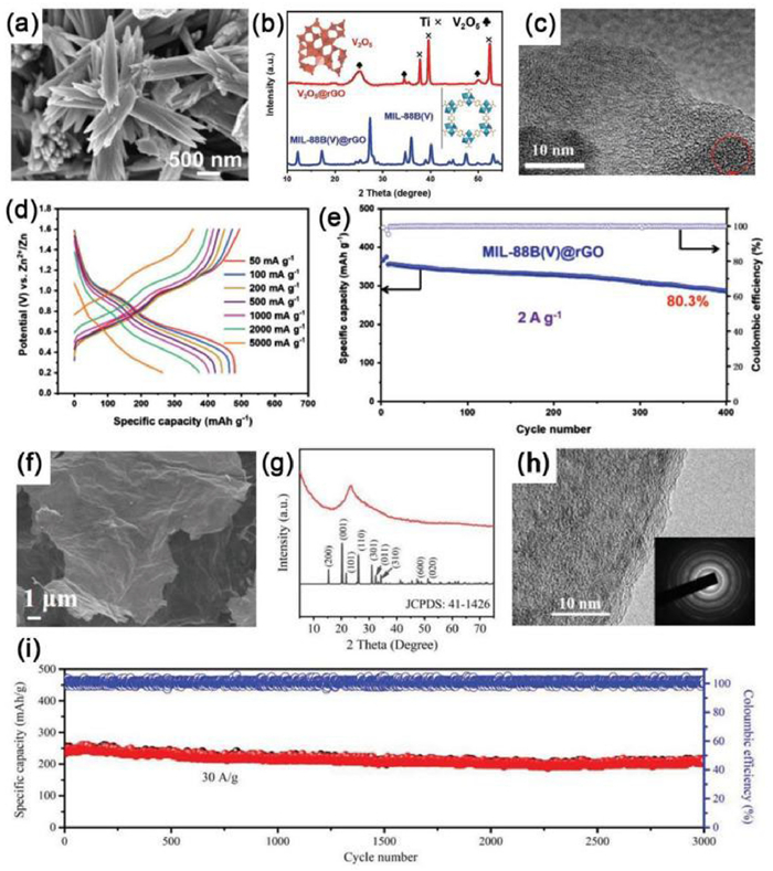
In the electrochemical results, the MIL-88B(V)@rGO cathode exhibited decent reversible capacity (479.6 mAh/g at 50 mA/g) and high capacity retention of 80.3% after 400 cycles at 2 A/g (Figs. 7d and e). The superior electrochemical properties could be attributed to the presence of amorphous V2O5 and the highly conductive rGO, which provide substantial active sites and channels for the adsorption and diffusion of Zn2+ and reduce the energy barrier for the migration of Zn2+. Wu's group [130] employed growing ultrathin amorphous V2O5 on graphene to construct a 2D heterostructure (A-V2O5/G). The SEM images demonstrated an ultrathin flat morphology of 2D A-V2O5/G with a nanosheet structure (Fig. 7f). The XRD pattern of the 2D A-V2O5/G heterostructure showed no diffraction peak of V2O5, indicating the formation of amorphous V2O5 (Fig. 7g). As shown in Fig. 7h, the 2D amorphous V2O5/graphene composite had a sandwich-like structure, and the image in the inset revealed no diffraction spots, further confirming the amorphous V2O5 in the 2D A-V2O5/G heterostructure. The 2D A-V2O5/G electrode for AZIBs exhibited an ultrahigh capacity of 489 mAh/g at 0.1 A/g, simultaneously delivering excellent long-term cyclability (86% capacity retention over 3000 cycles at 30 A/g) (Fig. 7i). Furthermore, Wu's group reported a 2D amorphous V2O5/graphene heterostructures (A-V2O5/G) with a highly stable layer-by-layer stacked structure [136]. After cycling, the capacity retention of A-V2O5/G was ~83% for up to 20,000 cycles at 30 A/g. The enhanced electrochemical properties could be ascribed to the strong synergistic effect between V2O5 and graphene, allowing for abundant active sites and barely any change in volume.
Graphene/V3O7·H2O (H2V3O8) composites: V3O7·H2O have been successively developed as a potential cathode material for AZIBs as it has the advantages of a 1D nanostructures and mixed valence states (V5+/V4+), allowing for ultrafast transport of electrons and ions [56]. Therefore, there are several research on the fabrication and application of graphene/V3O7·H2O composites with different nanostructures.
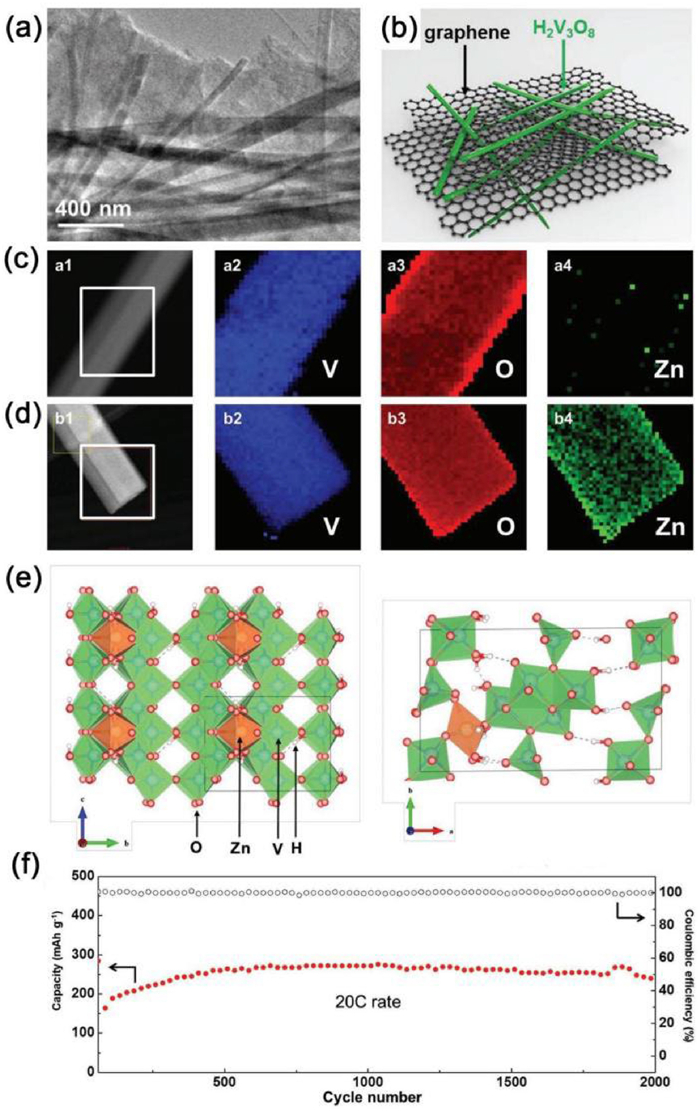
For example, Pang et al. [150] reported a H2V3O8 nanowire (NW)/graphene composite composed of H2V3O8 (or V3O7·H2O) NWs and graphene sheets made by a facile hydrothermal method. Wherein, the H2V3O8 NWs were well-distributed on the graphene films (Fig. 8a). The structure allows for a large contact area and a short charge transfer distance between the H2V3O8 NWs and the graphene, which can facilitate the transport of charge (Fig. 8b). Compared with Fig. 8c, Fig. 8d confirmed that the zinc ions were embedded on the surface and along the edge of the NWs. Furthermore, it can be seen that Zn was stably located at the center of the vacancy with a slight distortion towards the adjacent V atoms (Fig. 8e). Thanks to the combination of the superior crystal structure of V3O7·H2O NWs with the high conductivity of graphene, the H2V3O8 NW/graphene materials used as a cathode could stably for more than 2000 cycles at 20 C (Fig. 8f). Cao et al. [81] successfully synthesized V3O7·H2O nanobelts/rGO via a microwave approach. As a positive electrode for AZIBs, the composites delivered a high specific capacity of 410.7 and 385.7 mAh/g at a current density of 0.5 and 4 A/g, respectively. The electrochemical performance of this composite was superior to pristine V3O7·H2O, which can be ascribed to the presence of rGO, leading to fast electron transfer kinetics.
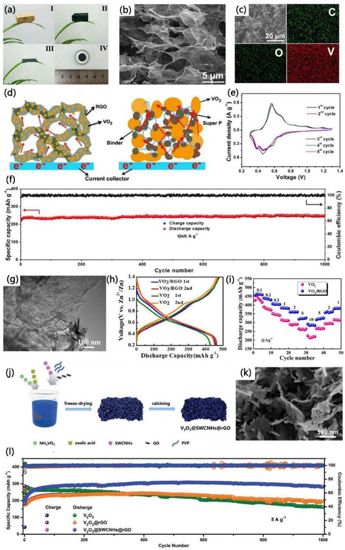
Graphene/VO2 composites: VO2 possesses large tunnels and a stable structure, which are beneficial for rapid intercalation and deintercalation of Zn2+ [164]. For the application in AZIBs, the graphene/VO2 composites exhibited excellent electrochemical properties. For example, Dai et al. [153] made a rGO/VO2 composite film as cathode for AZIBs through freeze-drying, high-temperature reduction, and mechanical compression (the corresponding optical images are shown in Fig. 9a). It was found that the composite had a porous network and the nanostructured VO2 grew on the surface of the rGO sheets (Fig. 9b). The SEM images and element mapping plots in Fig. 9c also show the uniform distribution of V, C, and O elements. As shown in Fig. 9d, the continuous cross-linked 3D porous structures are favorable for the electrolyte's ions to enter the ultra-thin nanostructure of VO2 on the rGO sheets and ensure the continuous transfer of electrons through the electrode. According to the cyclic voltammetry (CV) curves, the appearance of two pairs of broad redox peaks and three small redox peaks indicated a multi-step process of the insertion and extraction of zinc ion (Fig. 9e). For the application on the cathode of AZIBs, the rGO/VO2 composites exhibited ultralong cycling lifespan over 1000 cycles with a 99% capacity retention at 4 A/g (Fig. 9f). The excellent electrochemical performances could be attributed to the continuous porous network of the rGO/VO2 composite membrane, which provides an effective way for the transfer of electrons and ions, as well as buffers the volume changes caused by the process of Zn2+ insertion/extraction in VO2 during the discharge/charging processes.
Furthermore, VO2 possesses a variety of crystal types, including tetragonal VO2(A), monoclinic VO2(B, D, M), rutile VO2(R) and so on [164,165]. Among these, VO2(B) is widely used in research into cathode materials for AZIBs owing to its layered structure and large lattice spacing [29,56]. For example, Cui et al. [160] fabricated a VO2(B)/rGO composite via a simple hydrothermal approach. It was observed that rGO nanosheets were located on the surface of VO2(B) nanobelts, providing pathways for the transfer of electrons (Fig. 9g). When used as cathodic materials for AZIBs, the as-synthesized VO2(B)/rGO composite electrode exhibited an impressive capacity of 456 mAh/g at 100 mA/g (Fig. 9h), a remarkable rate capacity of 320 mAh/g at 5 A/g (Fig. 9i), and impressive cycling stability, which were better than those of pristine VO2(B). Moreover, Sun and co-workers [152] constructed a VO2(B)/GO composite material with abundant oxygen vacancies via a hydrothermal reaction. Profiting from the ample oxygen vacancies and GO, the VO2(B)/GO composite cathode exhibited an excellent performance of capable capacity of 423 mAh/g at 0.5 A/g.
Apart from the abovementioned VO2/graphene composites, hydrated vanadium dioxide (VO2·nH2O)/graphene has also been prepared and investigated with the advantages of larger interlayer spaces [164]. For instance, Jia et al. [158] fabricated VO2·0.2H2O nanocuboids loaded on graphene sheets (VOG), which exhibited excellent performance. Similarly, a simple microwave-assisted hydrothermal method was adopted by Shao and co-workers to synthesize VO2·0.26H2O nanobelts@rGO [159], which is considered as potential cathode materials for AZIBs. Furthermore, Huang et al. [157] introduced abundant oxygen vacancy defects and graphene modifications to successfully fabricate a spongy 3D hydrated vanadium dioxide composite (Od-HVO/rG) through a hydrothermal reaction. Benefiting from the robust structure and numerous active sites, Od-HVO/rG delivered considerable rate performance (428.6 mAh/g at 0.1 A/g) and remarkable long cycling life.
Graphene/V2O3 composites: V2O3 possesses a tunnel-like 3D structure for the intercalation and deintercalation of Zn2+ [164]. Recently, considerable effort has been devoted to designing graphene/V2O3 composites. For example, Li and colleagues [162] fabricated V2O3@graphene nanocomposite using V-MOF@graphene as a precursor through heat treatment. Thanks to the strong synergistic effect between graphene and V2O3, the structural destruction during zinc ions' (de)intercalation was effectively alleviated. When acting as cathodic materials for AZIBs, remarkably capacity of 450 mAh/g at 0.1 A/g and prolonged cycling life (87% capacity retention for more than 1000 cycles at 2 A/g) were obtained. Furthermore, Hong et al. [163] recently reported a multidimensional V2O3 nanosheets@single-walled carbon nanohorns@rGO (V2O3@SWCNHs@rGO) composite made by a facile freeze-drying approach as a high-performance cathode of AZIBs. A schematic illustration of the process of synthesizing V2O3@SWCNHs@rGO was displayed in Fig. 9j. It was found that the cross-linked V2O3 nanosheets were embedded in 3D rGO networks (Fig. 9k). As shown in Fig. 9l, electrochemical tests revealed that the V2O3@SWCNHs@rGO cathode had a capacity of 283 mAh/g over 1000 cycles at a current density of 5 A/g, which was greater than that of pristine V2O3 and V2O3@rGO electrodes.
Among the vanadium-based compounds, vanadates with a layered structure are regarded as one of the most attractive Zn2+ host materials [166]. According to the different pre-intercalated species (the alkali metal cations Na+ and K+, the alkali earth metal cations Mg2+ and Ca2+, the transition metal cations Cu2+ and Ag+, and other cations such as NH4+), they can be classified into alkali metal vanadates [167–173], alkali earth metal vanadates [39,174], transition metal vanadates [166,175–180] and other vandates [128,181,182], which are important classifications for energy storage. In this section, the strategy of designing graphene/vanadate composites is systematically introduced.
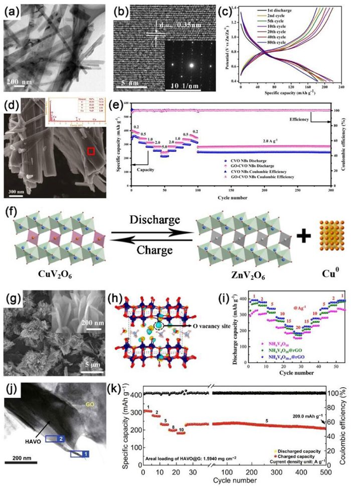
Graphene/alkali metal vanadates: Alkali metal vanadates, including sodium vanadates and potassium vanadates and so on, can exhibit excellent electrochemical properties [56]. For potassium vanadate (K2V3O8), as the charge–discharge cycles continue, low conductivity and fast capacity decay seriously affect its electrochemical performance [172]. To solve these problems, Li et al. [172] compounded GO and layered K2V3O8 to obtain a K2V3O8@GO composite as a cathode in AZIBs with a stable structure and superior conductivity, which significantly enhanced the electrochemical properties of the as-fabricated battery. In addition, sodium vanadates have also been widely investigated [168,171,173]. For example, Zhou and colleagues [173] fabricated a pilotaxitic Na1.1V3O7.9 nanoribbons/graphene composite via facile hydrothermal and freeze-drying approach. The TEM images of Na1.1V3O7.9@rGO revealed that the Na1.1V3O7.9 nanoribbons were evenly wrapped by the graphene membrane (Fig. 10a). Fig. 10b shows that the spacing of the lattice fringes of the obtained composite was ~0.35 nm, corresponding to the (004) plane. The introduction of graphene effectively increased the conductivity and buffered the stress and change in volume during charging–discharging process of the battery. When used as the cathode for AZIBs, the Na1.1V3O7.9@rGO composites delivered high reversibility from the first cycle to the 80th cycle (Fig. 10c) and excellent cyclic stability.
In particular, several studies have focused on NaxV2O5·nH2O. According to previous research, the layered and hydrated V2O5 has drawn much attention with its open crystal structure, which uses H2O molecules or Na+ as pillars to stabilize the layered structure and shield the electrostatic interactions between the inserted cations during cycling [170]. For example, Tang et al. [167] synthesized a flexible free-standing paper electrode named as rGO/δ-NaxV2O5·nH2O by a vacuum filtration way. When tested as cathodic material for AZIBs, the composites delivered an excellent specific capacity of 1.87 mAh/cm2, corresponding to 374.9 mAh/g for the active material. Furthermore, Xu et al. [169] produced a freestanding, porous, and hierarchical composite material as an electrode by one-pot hydrothermal self-assembly followed by vacuum filtration. The material was composed of bilayered NaxV2O5·nH2O (NVO) nanobelts, rGO and CNTs. When investigated as a cathode for AZIBs, it delivered an admirable long-term capacity retention of 83.1% over 1800 cycles under 10 A/g.
Graphene/alkali earth metal vanadates: In recent years, alkali earth metal vanadates have gained the interests of researchers, indicating their potential for development [39,56,174]. Hu et al. [39] adapting intercalating Ca2+ into hydrated V2O5 and integrated with rGO to obtain CaVOH/rGO composite. When tested for AZIBs, the composite as the cathode exhibited excellent storage capacity of 409 mAh/g at 0.05 A/g. Moreover, an admirable specific capacity of 299 mAh/g was obtained after 2000 cycles at 4 A/g. In addition, Wu et al. [174] manufactured novel CaV8O20·3H2O nanoribbons with graphene through a hydrothermal process (abbreviated as CaVO-400, as it contained 400 mg of GO). The CaVO-400 was used as a cathode for AZIBs and delivered a high reversible capacity of 290.9 mAh/g at 1 A/g over 100 cycles and a good cycling performance of 56.4 mAh/g at 3 A/g over 10,000 cycles.
Graphene/transition metal vanadates: Graphene/transition metal vanadates have also been reported, such as Co0.25V2O5·nH2O [175], Ag2V4O11@rGO [177], GO—CuV2O6 nanobelts [166], which exhibited satisfying electrochemical properties. Liu et al. [166] designed GO wrapped CuV2O6 nanobelts (denoted as GO—CVO NBs) for AZIBs. As shown in Fig. 10d, the SEM image revealed the same wide aspect ratio between GO—CVO NBs and CVO NBs, in which the CuV2O6 nanosheets were apparently wrapped by the GO nanosheets. When investigated as the positive electrode of AZIBs, GO—CVO NBs composites provided better rate performance at higher capacities than CVO NBs (Fig. 10e). The remarkable electrochemical properties could be attributed to the reversible phase transformation between CuV2O6 and ZnV2O6 (Fig. 10f). The electrochemical reaction mechanism between them is as follows:
|
|
(5) |
Graphene/other vanadates: In addition to materials discussed above, vanadium oxide have also been combined with other elements to form vanadate and composited with graphene to produce advanced materials [128,181–184]. For instance, a simple one-step hydrothermal method was adapted to induce oxygen vacancies in NH4V4O10 nanobelts alongside modification of graphene (denoted as NH4V4O10-x@rGO) by Cui et al. [128]. The NH4V4O10-x@rGO composite showed a 3D flower-like structure, providing ample contact area between the electrode materials and the electrolyte (Fig. 10g). The crystal structure of NH4V4O10-x is illustrated in Fig. 10h, the presence of oxygen vacancies allowed the rapid diffusion of Zn2+ and made the structure of NH4V4O10 stable. Consequently, the NH4V4O10-x@rGO composite delivered outstanding rate ability of 211 mAh/g at the 15 A/g as the cathode in AZIBs (Fig. 10i). The as-prepared NH4V4O10-x@rGO electrode provided new insights for the design of cathode materials for AZIBs. Beyond that, Al0.34V5O12·2.4H2O (AlVOH) nanoribbons compounded with rGO were synthesized by Lin's groups [181]. In particular, the introduction of Al3+ played a role in increasing the water content of the interlayer structure, making the electrochemical performance of the composites more stable. Furthermore, Zhang et al. [184] utilized a simple hydrothermal followed by freeze-drying treatment to fabricate the H11Al2V6O23.2@graphene (HAVO@G) composite. The TEM image indicated that the H11Al2V6O23.2 nanobelts were surrounded by the graphene (Fig. 10j). When used as the cathode for AZIBs, the HAVO@G composite delivered superb rate performance (Fig. 10k).
Vanadium phosphates are another important group of vanadium-based materials, including vanadium fluorophosphates (Na3V2(PO4)2F3) [185], Na3V2O2(PO4)2F [186] and so on. Composites of graphene with vanadium phosphate materials can achieve high electronic conductivity and a stable structure, thus further optimizing its electrochemical capabilities [185,186].
An impressive work was carried out by Huang et al. [186], who developed Na3V2O2(PO4)2F nanoparticles covered by graphene (named N3VOPF@rGO) through a microwave-assisted solvothermal followed by a postheat treatment (Fig. 11a). The crystal structure of N3VOPF is shown in the set of Fig. 11a. It displayed a 3D structure consisting of alternating multilayered structures, which are made up of [VO5F] octahedra and [PO4] tetrahedra shared by the oxygen atoms in the corner. The double [VO5F] shared in the corner of the F atoms can connect and support the interlayer, providing favorable stability and large channels for ion diffusion. The N3VOPF materials with different percentages of GO (3.59, 4.95, and 9.17 wt%) are labeled as N3VOPF@rGO-1, −2, and −3, respectively. The SEM images of them and pure N3VOPF are displayed in Figs. 11b−e, showing that the wrapped graphene formed a successive 3D conductive network as its content increased. As shown in Fig. 11f, compared with pure N3VOPF, N3VOPF@rGO-1 and N3VOPF@rGO-3, a reversible capacity of N3VOPF@rGO-2 cathode could reach 63.9 mAh/g over 5000 cycles at 30 C, which could be ascribed to the appropriate content of rGO and the optimized composition of the electrolyte. The electrochemical reaction during the ions insertion and extraction in N3VOPF@rGO-2 can be described as follows (Fig. 11g):

First cycle:
|
|
(6) |
|
|
(7) |
For subsequent cycles:
|
|
(8) |
Similarly, Guan et al. [185] adapted a microwave hydrothermal and calcination strategy to prepare a 3D composite of mesoporous Na3V2(PO4)2F3 nanocuboids wrapped by rGO (N3VPF@rGO). When tested as a cathode for AZIBs, the composite delivered a high rate capacity of 93.9 mAh/g at 20 C and sustained only 0.0074% capacity decay per cycle after 5000 cycles under 15 C. The introduction of highly conductive rGO constructed a whole electron migration pathway for the redox reaction and inhibited the accumulation of Na3V2(PO4)2F3 particles.
Oxygen-free vanadium-based compounds, such as vanadium sulfides (VS4 [187,188] and VS2 [189]), vanadium nitrides (VN [190–192]) and vanadium selenides (VSe2 [193]), have been considered as cathode materials because of their unique and favorable electrochemical properties [56].
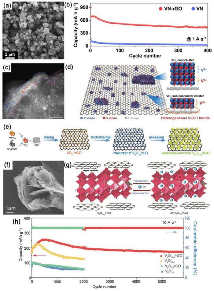
VN has made significant progress in the field of zinc ion-based energy storage [190–192]. However, the applications of VN are limited due to the unstable structure and poor electrical conductivity [125]. According to previous reports, combining VN with conductive carbon materials (such as graphene) is an effective way to enhance the structural stability and conductivity [194–196]. For instance, Park et al. [191] successfully constructed a 3D porous VN-rGO composite through spray pyrolysis and subsequent one-step nitridation. Fig. 12a displayed the dispersive and spherical microspheres morphology of VN-rGO, and the average size of the microspheres was 0.87 µm. When utilized as the cathode for AZIBs, the VN-rGO microspheres provided a reversible capacity of 445 mAh/g over 400 cycles at 1.0 A/g (Fig. 12b). The outstanding electrochemical performance of VN-rGO composites could be ascribed to the VN nanocrystals being uniformly anchored to the 3D porous rGO matrix, which accelerated the storage kinetics of zinc ions and ensured the robust structure of the cathode. Furthermore, Yang and co-workers [192] used doping technology based on vanadium nitride/graphene to obtain VN@nitrogen-doped graphene (VN@NGr) as an electrode material, which maintained 96% and 70% capacity retention after 75,000 cycles and 26,000 cycles at 0.1 and 20 A/g, respectively.
In addition to VN, vanadium sulfides, including VS2 and VS4, have attracted the interest of researchers owing to their large interlayer spacing and great electrochemical properties [188,197]. For example, Chen et al. [189] invented a new 2D hierarchical composite by a one-step solvothermal method, which comprised of ultrathin VS2 nanosheets vertically grown on graphene sheets (rGO-VS2). Thanks to the unique hierarchical structure and synergistic advantages between the VS2 and graphene nanosheets, the rGO-VS2 composite exhibited exceptional performance as the cathode material for AZIBs. With regard to VS4, Qin et al. [188] prepared VS4 anchored on rGO (VS4@rGO) through a facile hydrothermal route. In the electrochemical results, the prepared composites used as a cathode had high capacity (180 mAh/g) and high capacity retention (93.3% after 165 cycles at 1 A/g). The excellent electrochemical performance can be attributed to the unique crystal structure of VS4 and the high conductivity of rGO.
Apart from the vanadium-based compounds discussed above, some other vanadium-based materials will be briefly introduced in this section, such as VOx−G heterostructures [198], V6O13−x/rGO [199] and other composite materials [200].
An interesting research was reported by Mai's group [198], who artificially fabricated a VOx sub-nanometer cluster/rGO (named VOx−G heterostructure) cathode material consisting of interfacial V-O-C bonds. Moreover, it can be seen that Zn2+ ions were mainly distributed in the VOx nanoclusters' regions, which revealed an interfacial Zn2+ ion storage process (Fig. 12c). The VOx−G heterostructure acted as a cathode material and provided a capacity of 174.4 mAh/g at 100 A/g, indicating that the battery took only 6.3 s to discharge completely, suggesting remarkable performance for AZIBs. Moreover, to unravel the novel storage mechanism of Zn2+, researchers developed a schematic diagram of the VOx−G heterostructure (Fig. 12d). According to other results of characterization, Zn2+ ions are mainly stored at the interface of VOx and rGO, resulting in abnormal change in valence compared with conventional mechanisms and exploiting the storage ability of active, non-energy storing but highly conductive rGO. Similarly, Ma's group [199] successfully constructed an oxygen vacancy-enhanced heterojunction of V6O13−x/rGO as a cathode through electrostatic assembly and annealing techniques (Fig. 12e). As seen in Fig. 12f, V6O13−x/rGO nanoparticles were loosely dispersed on nanosheets of different sizes. The nanosheets were interconnected in a petal-like manner, exposing massive active sites to contact with Zn2+. Furthermore, the reversible process of insertion/extraction of Zn2+ in V6O13−x/rGO was illustrated in Fig. 12g, which exhibited the superior structural stability of V6O13−x/rGO after long-term cycling. When assembled into AZIBs, the V6O13−x/rGO cathode could stably cycle for more than 5800 cycles with a favorable capacity retention rate of 96% at 10 A/g (Fig. 12h). The excellent performance of V6O13−x/rGO cathodes is mainly attributed to the abundant oxygen vacancies in V6O13−x, as well as the external electric field formed by the heterogeneous interface between V6O13−x and rGO, realizing the rapid migration of Zn2+ from the heterointerfaces to the lattice.
To date, vanadium-based compounds have been broadly supposed and investigated as promising cathodes for AZIBs. However, because of the intense mutual electrostatic interaction between its crystal structure and Zn2+, as well as the destruction of crystal structure of during the embedding process of Zn2+, the electrochemical performance of the batteries has been reduced. According to the studies mentioned above, graphene/vanadium-based composite cathode materials, including graphene/VxOy, graphene/vanadates, graphene/vanadium phosphates, graphene/oxygen-free vanadium-based compounds, and others, not only provide a greater number of active sites, but also enhance the structural stability and accelerate the reaction kinetics (Table 2). Consequently, the electrochemical performances of AZIBs with graphene/vanadium-based composite cathodes improved significantly.
DownLoad:
CSV
| Materials | Synthesis method | Current density (A/g) | Cycle number | Capacity retention ratio (%) | Specific capacity (mAh/g, mA/g) | Refs. |
| Graphene/vanadium-based composites | ||||||
| V2O5@graphene | – | 1 | 1000 | – | 378, 2000 | [32] |
| CaVOH/rGO | Hydrothermal and freeze-drying treatment | 4 | 2000 | – | 409, 50 | [39] |
| V2O5−x@rGO | – | 0.5 | 1050 | 90.6 | 153.9, 15,000 | [41] |
| NH4V4O10-x@rGO | Hydrothermal | 15 | 2000 | 90.5 | 391, 100 | [128] |
| A-V2O5/G | Freeze-drying and annealing | 30 | 3000 | 87 | 489, 100 | [130] |
| V2O5/xG | Solvothermal and calcination | 10 | 6000 | 82.4 | 270, 100 | [131] |
| V2O5/GO | Solution method followed by freeze drying | 20 | 10,000 | 90.8 | 525, 100 | [132] |
| V2O5/VG/CC | – | 2 | 5000 | 85 | 370, 200 | [133] |
| VOGH | Freeze-thaw | 1 | 1000 | – | 240.5, 1000 | [134] |
| Amorphous V2O5@rGO | In-situ irreversible conversion | 2 | 400 | 80.3 | 479.6, 50 | [135] |
| A-V2O5/G | 2D template ion-adsorption | 30 | 20,000 | 83 | 447, 300 | [136] |
| V2O5@LIG | Defect-induced adsorption | 1 | 200 | 92.5 | 265.4, 1000 | [137] |
| S-V2O5/rGO | Hydrothermal and calcining | – | – | – | 610, 100 | [138] |
| AVO–EGO | Spray drying technique | 5 | 3000 | – | 462, 200 | [139] |
| V2O5·nH2O-graphene | In-situ self-transformation | 10 | 5000 | 100 | 466, 100 | [140] |
| V2O5·nH2O/rGO-PVA | Hydrothermal and vacuum filtration | 0.5 | 300 | 78.3 | 553, 100 | [141] |
| V2O5-rGO | – | 0.1 | 200 | – | 135, 100 | [142] |
| (Mn+Zn)-V2O5 NR/rGO | – | 4 | 1950 | 77 | 291, 500 | [143] |
| VOG | Hydrothermal | 10 | 1200 | 72 | 342, 1000 | [144] |
| Ov-PVO/G | Ball-milling | 10 | 3000 | 84.3 | 508.3, 200 | [145] |
| V3O7·H2O/rGO | Microwave-assisted heating | 4 | 1000 | 99.6 | 385.7, 4000 | [146] |
| H2V3O8 nanorods/graphene-523 K | Hydrothermal and calcination | 2 | 200 | 73.3 | 401, 200 | [147] |
| V3O7⋅H2O/Graphene | Hydrothermal | 10 | 2000 | 80.5 | 463.3, 1000 | [148] |
| V3O7·H2O/rGO | Hydrothermal | 1.5 | 1000 | 79 | 245/1500 | [149] |
| H2V3O8 NW/Graphene | Hydrothermal | 20 C | 2000 | 87 | 394, 1, 3 C | [150] |
| VO2-SDBS@rGO | Solvothermal | 8 | 500 | 79.8 | 437.8, 500 | [151] |
| VO2(B)/GO | Hydrothermal | 15 | 2750 | 88 | 423, 500 | [152] |
| rGO/VO2 | Freeze-drying, high temperature reduction and mechanical compression | 4 | 1000 | 99 | 280, 100 | [153] |
| VO2/G nanobelts | Hydrothermal | 5 | 1000 | – | 731, 100 | [154] |
| H-VO2@GO | Hydrothermal | 10 | 1500 | 96.1 | 400.1, 500 | [155] |
| P-VO2@rGO | Spray pyrolysis and heat-treatment | 1 | 350 | 80 | 342, 100 | [156] |
| Od-HVO/rG | Hydrothermal | 10 | 2000 | 95.8 | 428.6, 100 | [157] |
| VOG | Microwave-assisted solvothermal | 8 | 1000 | 87 | 423, 250 | [158] |
| VO2·0·26H2O@rGO | Microwave-assisted hydrothermal | 5 | 1200 | 94.9 | 386, 100 | [159] |
| VO2(B)/rGO | Hydrothermal | 5 | 1000 | 90 | 456, 100 | [160] |
| VO2@GO | Hydrothermal | 5 | 1000 | 88 | 323, 100 | [161] |
| V2O3@graphene | – | 2 | 1000 | 87 | 450, 100 | [162] |
| V2O3@SWCNHs@rGO | Freeze-drying and post-calcination treatment | 5 | 1000 | – | 422, 200 | [163] |
| GO—CVO NBs | Hydrothermal | 5 | 3000 | 99.3 | 427, 100 | [166] |
| rGO/δ-NaxV2O5·nH2O | Vacuum filtration | 2 | 4000 | 92 | 374.9, 100 | [167] |
| rGO/NVO | Vacuum filtrating | 5 | 2000 | 94 | 410, 100 | [168] |
| NVO-rGO/CNT | Hydrothermal self-assembly and vacuum filtration | 10 | 1800 | 83.1 | 459.1, 500 | [169] |
| rGO/δ-NVO | Hydrothermal | 2 | 1000 | 70.5 | 362.4, 100 | [170] |
| NVO@G | Molten salt method | 5 | 4400 | 85.7 | 220, 300 | [171] |
| K2V3O8@GO | – | 5 | 2000 | 75.7 | 334.8, 100 | [172] |
| Na1.1V3O7.9@rGO | Hydrothermal followed by freeze-drying | 0.3 | 100 | 92.9 | 220, 300 | [173] |
| CaVO-400 | Hydrothermal | 3 | 10,000 | 95 | 290.9, 100 | [174] |
| CoVO-150 | – | 20 | 2000 | 82.1 | 230.3, 5000 | [175] |
| FeVO4·nH2O@rGO | Hydrothermal | 1 | 1000 | – | 100, 1000 | [176] |
| Ag2V4O11@rGO-90 | In-situ hydrothermal | 5 | 300 | 93.2 | 328, 100 | [177] |
| ZVOH@rGO | – | 12 | 9800 | 75.6 | 286.7, 30,000 | [178] |
| CVO/CNT-rGO | Hydrothermal | 5 | 1000 | 87 | 397, 200 | [179] |
| MnVOH/rGO | Hydrothermal | 0.1 | 100 | 80 | 361, 100 | [180] |
| AlVOH/rGO | Hydrothermal | 20 | 2000 | 94 | 407.8, 200 | [181] |
| AlVOH/rGO | Hydrothermal | 4 | 1300 | – | 405, 100 | [182] |
| LaVO/rGO | Hydrothermal | 10 | 6000 | 88 | 298, 300 | [183] |
| HAVO@G | Hydrothermal and freeze-drying | 5 | 900 | 94 | 305.4, 100 | [184] |
| N3VPF@rGO | Microwave hydrothermal and calcination | 15 C | 5000 | 99.9 | 126.9, 0.5 C | [185] |
| Na3V2O2(PO4)2F@rGO | Microwave-assisted solvothermal and postheat treatment | 30 C | 5000 | – | 127, 0.5 C | [186] |
| VS4@NGA | Hydrothermal and freeze-dehydration | 10 | 1000 | 85 | 320, 100 | [187] |
| VS4@rGO | Hydrothermal | 1 | 165 | 93.3 | 180, 1000 | [188] |
| rGO-VS2 composite | Solvothermal | 5 | 1000 | 93 | 238, 100 | [189] |
| VN@rGO | Electrostatic self-assembly | 20 | 10, 900 | 91.24 | 267, 1000 | [190] |
| VN-rGO microspheres | Spray pyrolysis and nitridation | 1 | 400 | 78 | 809, 100 | [191] |
| VN@NGr | – | 1 | 1000 | ~100 | – | [192] |
| rGO-VSe2 | Hydrothermal | 0.5 | 150 | 91.6 | 221.5, 500 | [193] |
| VOx-G heterostructure | – | – | – | – | 443, 100 | [198] |
| V6O13−x/rGO | Electrostatic assembly and annealing strategy | 10 | 5800 | 96 | 424.5, 100 | [199] |
| Mo-V-S-GO | Hydrothermal | 10 | 8000 | 90.2 | 389, 500 | [200] |
Recently, significant progress have been made in the field of inorganic materials, while organic compounds have also garnered widespread attention owing to their low toxicity, sustainability, structural diversity, and molecular-level controllability [201]. In this section, we systematically delve into organic materials composited with graphene, categorizing them into three types according to their active sites: Quinones-based derivatives [202,203], aniline–based linear polymers [201,204–208], and others [209–211]. More details about the electrochemical performance could be found in Table 3.
DownLoad:
CSV
| Materials | Synthesis method | Current density (A/g) | Cycle number | Capacity retention ratio (%) | Specific capacity (mAh/g, mA/g) | Refs. |
| Graphene/organic composites | ||||||
| POLA/G | Hydrothermal | 10 | 5000 | 90 | 225, 100 | [201] |
| DTT@rGO | Hydrothermal | 10 | 4000 | 100 | 259.2, 100 | [202] |
| BNDTH/rGO | Solvent exchange composition method | 10 | 400 | 65 | 296, 50 | [203] |
| rGO/PANI | All-freeze-casting | 1 | 500 | 94.6 | 175.5, 100 | [204] |
| MEG/PANI composite | Solvent-exfoliated and acid-modified process | 2 | 1000 | 72.7 | 184.5, 200 | [205] |
| PONEA/graphene | Sonication and hydrothermal | 10 | 4800 | 85 | 329, 100 | [206] |
| PANI-GO/CNT | – | 3 | 2500 | – | 233, 100 | [207] |
| PGO | In-situ electrochemical method | 0.2 | 200 | 89.3 | 200, 400 | [208] |
| GH | In situ electrochemical oxidation | 10 | 7000 | 90 | 225, 50 | [209] |
| G-Aza-CMP | Solvothermal condensation reaction and hydrothermal | 10 | 9700 | 91.2 | 456, 50 | [210] |
| DNPT/rGO | – | 0.5 | 1000 | 100 | – | [211] |
Quinone compounds exhibit high solubility in certain organic electrolytes, resulting a reduction in the content of active material and a significant capacity fading of battery. However, due to their limited solubility in water, and because the carbonyl group in quinone will be reduced to as N-type materials bind with Zn2+ or H+ during the discharge process, the utilization of quinone–based derivatives in AZIBs has attracted significant attention [212]. For instance, Zhang et al. [202] designed and prepared rGO-wrapped carbonyl-containing organic composites (DTT@rGO) by engineering noncovalent interaction. The AZIBs based on DTT@rGO cathode delivered considerable capacity retention (100% after 4000 cycles at 10 A/g). Moreover, in response to the low conductivity of the sulfur-based heterocyclic organic quinone known as benzo[b]naphtho[2′,3′:5,6][1,4]dithiino[2,3-i]thianthrene-5,7,9,14,16,18-hexone (BNDTH), Sun et al. [203] adapted a solvent exchange strategy to synthesize a BNDTH/rGO composite, in which the rGO sheets well wrapped the active BNDTH bulk (Fig. 13a). Compared with pure BNDTH, BNDTH/rGO composite had a higher reversible capacity of 174.7 mAh/g (Fig. 13b). Fig. 13c showed that after 4680 h, the BNDTH/rGO||Zn cell sustained a capacity of 283 mAh/g with 95% capacity retention at 0.05 A/g, demonstrating favorable cycling stability. The exceptional electrochemical properties could be attributed to the extended π-conjugated structure of BNDTH and the strong π–π intermolecular interactions with rGO.
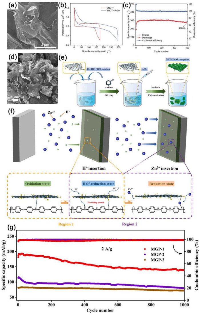
As members of the aniline–based linear polymers, polyaniline (PANI) [204,205,207,208], poly-quinol-phenylenediamine (POLA) [201] and poly-quinone-phenylenediamine (PONEA) [206] have drawn much attention because of their good conductivity and specific redox units [205,207]. However, poor cycling stability, low conductivity, and the deficiency of active sites have limited the development of PANI [205]. Consequently, researchers have attempted to construct graphene/PANI composites to solve these issues. For instance, Xu et al. [201] successfully used a simple hydrothermal method to synthesize POLA/graphene (POLA/G) composite material. The POLA/G composite as cathode demonstrated excellent rate capacity (225 mAh/g at 0.1 A/g and 152 mAh/g at 20 A/g) and long cycle life (90% capacity retention after 5000 cycles at 10 A/g). Similarly, Liao et al. [205] successfully prepared a functionalized composite of functional commercial graphene (MEG) and PANI (denoted as MGP-1) through an in situ chemical oxidative polymerization process (Fig. 13e). The PANI was uniformly distributed on the surface of the MEG layer in a configuration of nanowire arrays (Fig. 13d). Furthermore, Fig. 13f showed the insertion mechanism of Zn2+ and H+ into the MGP-1 cathode of AZIBs during discharging. In the second step, with an increase of in the redox potential, Zn2+ ions were attracted to the unsaturated -N·- units and electrophilic oxygen-based groups when embedding into the MGP-1 cathode to form a relatively more stable -N-Zn-O- structure (Region 2). This structure had an abundance of Zn2+ ions and allowed more electrons to be transferred to the PANI chains, which greatly improved the capacitive properties of the MGP-1 composites. Furthermore, MGP-2 and MGP-3 composites with a mass ratio of MEG to aniline of 1:4 and 5:1 were fabricated to be compared with MGP-1. As a result, when tested as cathode for AZIBs, MGP-1 exhibited better electrochemical properties compared with MGP-2 and MGP-3 (Fig. 13g). The outstanding electrochemical behaviors can be ascribed to the large conductive network of GMP-1 and the formation of a stable -N-Zn-O- structure during discharging process.
Apart from these graphene/organic material composites, other organic materials combined with graphene have also been reported to effectively promote the electrochemical performance of AZIBs [209–211]. In particular, Li et al. [210] fabricated a graphene/aza-fused π-conjugated microporous polymer composite (G-Aza-CMP) composite material via a hydrothermal method. When the material was used as the cathode for AZIBs, it exhibited long-term cycling life of 91.2% capacity retention over 9700 cycles at 10 A/g. The excellent electrochemical properties of G-Aza-CMP electrodes can be assigned to the graphene introduced abundant active sites of H+ and Zn+ to accelerate the reaction kinetics, as well as the combination of the large π-conjugated structure of Aza-CMP and graphene, which promoted the electrical conductivity and stability.
Apart from the aforementioned graphene-based composites, other graphene composites will be briefly discussed in this section: Transition metal sulfides [213–216] and others [37,217–221]. More details about the electrochemical performance could be found in Table 4.
DownLoad:
CSV
| Materials | Synthesis method | Current density (A/g) | Cycle number | Capacity retention ratio (%) | Specific capacity (mAh/g, mA/g) | Refs. |
| Other graphene-based composites | ||||||
| ZnTe/rGO | Hydrothermal | 0.5 | 300 | – | 225, 100 | [37] |
| MoS2-rGO | Solvothermal reaction | 20 | 1000 | 65.7 | 303.1, 200 | [213] |
| MoS2/graphene | Hydrothermal | 1 | 1800 | 88.2 | 285.4, 50 | [214] |
| NiS2/rGO | – | 4 | 2000 | 80.5 | 209.4, 1000 | [215] |
| MoS1.8Se0.2/rGO | Hydrothermal | 1 | 1000 | 74.1 | 213.6, 100 | [216] |
| NiHCF/rGO hybrid | – | 0.2 | 1000 | 80.3 | 94.5, 5 | [217] |
| Te-rGO | Hydrothermal | 6 | 2500 | 99.9 | 621, 50 | [218] |
| MoSSe/rGO | Hydrothermal | 2 | 1200 | 83 | 272.6, 100 | [219] |
| Holey graphene oxide | Diazotization | 10 | 4000 | 98 | 234, 100 | [220] |
| GSAF@KVO—HCF | Liquid-phase polymerization process | 1 | 1000 | – | 162, 100 | [221] |
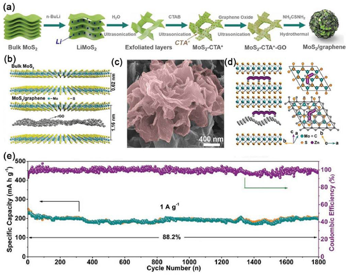
For example, Li et al. [214] synthesized MoS2/graphene sandwich-like heterostructures by inserting graphene into the MoS2 gallery (Fig. 14a). With the intercalation of graphene into MoS2, the interlayer distance of MoS2 expanded from 0.62 nm to 1.16 nm (Fig. 14b). In addition, according to the SEM results, MoS2/graphene hybrids featured a typical flower-like morphology (Fig. 14c). Fig. 14d depicts the migration pathways of Zn2+ in structural models of bulk MoS2 (top) and MoS2/graphene (bottom). The cathode made from the MoS2/graphene composite retained 88.2% of the initial capacity after charge−discharge 1800 cycles at 1 A/g (Fig. 14e). The superb electrochemical performance could be ascribed to the flower-like structure of MoS2/graphene, which facilitated the diffusion of Zn2+, promoted penetration of electrolyte, and ensured high structural stability. Shi et al. [215] demonstrated a high-density NiS2/rGO composite as a cathode for AZIBs. The compact networks of rGO created rapid electron pathways to accelerate reaction kinetics and reinforced the inner structure of the whole electrode. The NiS2/rGO composite as cathode exhibited excellent cycling performance, which maintained excellent capacity retention of more than 80.5% after 2000 cycles at 4 A/g. In addition, Guo et al. [218] constructed a new Te-rGO cathode material by tightly wrapping Te nanorods with a low percentage of graphene. When tested for AZIBs, the cathode with Te-rGO displayed excellent cycling stability with a rate of capacity decay of 0.005% per cycle after 2500 cycles at 6 A/g.
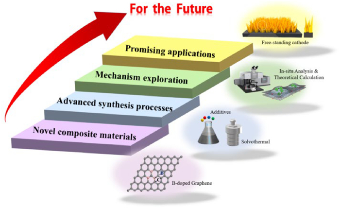
In conclusion, we have provided an overview of the recent progress in graphene-based materials applied as the cathode of AZIBs, including graphene/manganese-based composites, graphene/vanadium-based composites, graphene/organic composites and other graphene composites. Their typical properties, including synthetic methods and electrochemical performances are listed in Tables 1–4. Obviously, simple graphene composite materials have multiple inherent advantages for enhancing the electrochemical properties of AZIBs. Firstly, as a carbon material, graphene possesses excellent mechanical flexibility, a large surface area, and light weight, which is very beneficial for the construction of flexible devices. Secondly, graphene can provide abundant active sites for accelerating the diffusion of Zn2+. Thirdly, GO is the oxidized product of graphene, characterized by high catalytic activity and rich oxygen-containing functional groups on its surface. Lastly, rGO possesses higher conductivity and ideal mechanical properties. As advanced cathode materials, graphene-based composites provide hope for the development and application of high-performance of AZIBs, including following advantages: They have high electrical conductivity, good structural stability, and long-term cycling life; they provide many efficient electron transport pathways to accelerate the reaction kinetics; and they have a larger interlayer space for the insertion of Zn2+, leading to high practical capacity. Although much research has explored the cathode materials of AZIBs, there are still some existing challenges remain to be solved. To further improve the electrochemical properties of graphene-based composite materials, some suggestions are discussed as follows (Fig. 15):
(1) Novel composite materials
The main graphene-based composite materials applied on cathode of AZIBs include graphene/manganese-based composites, graphene/vanadium-based composites, graphene/organic material composites, and others. Although there are many types of existing graphene-based cathode materials with improved electrochemical properties, it is still necessary to explore novel graphene-based composites, which may achieve better electrochemical properties. For example, doping and co-doping different atoms (S, N, P, B, etc.) into graphene can produce graphene with different levels of electrochemical activity. Furthermore, graphene can also be integrated with carbon nanomaterials, such as carbon nanotubes and carbon nanofibers, to serve as a conductive substrate to extend the cycle life of batteries. The carbon nanomaterials offer a large specific surface area, high electrical conductivity and remarkable mechanical properties, all of which enhance the physical and chemical properties of the composite. Moreover, other metal oxides like Co3O4, TiO2, and NiO, known for their high theoretical specific capacities and strong energy storage capabilities, present a promising research direction for graphene-based composites. Additionally, the unique open-frame structure and ion transport channels of Prussian blue analogues suggest that their combination with graphene holds considerable potential. Meanwhile, changing the morphology and constructing different structures of graphene-based composites would also have a significant impact on their electrochemical properties. Therefore, with the development and research of different graphene-based composites, the future application of them as the cathode of AZIBs will attract more and more attention and stimulate greater potential.
(2) Advanced manufacturing processes
The hydrothermal method is extensively utilized in the preparation of graphene-based composites thanks to its obvious advantages, such as convenient operation, low cost, and products with good dispersion and high purity. During the hydrothermal reaction, the morphology, crystal structure, and the grain purity of the nanoparticles can be controlled by regulating the reaction conditions. To the best of our knowledge, researchers have proposed some effective ways to optimize hydrothermal reactions. For example, the microwave hydrothermal method is utilized to accelerate the reaction's rate and reduce its reaction temperature. Another approach is to introduce surfactants, including sodium dodecyl sulfate and cetyltrimethylammonium bromide, to further control the growth of crystals and reduce the effect of electrostatic attraction between oppositely charged ions. Furthermore, it is crucial to note that the application of supercritical hydrothermal methods has also been reported, which is a promising aspect. Moreover, exploring other organic surfactants will also promote the application of hydrothermal technology in the synthesis of graphene-based composite materials.
Apart from the hydrothermal method, other various synthesis pathways have been chosen, such as solvothermal treatment, electrochemical deposition, and refluxing−annealing, and other methods. However, most of these methods have rarely been used by researchers. Therefore, taking them as research directions in the future may make great progress.
(3) Exploration of the mechanism
At present, for application as the positive electrode of AZIBs, graphene is primarily used as conductive substrate, conductive additive, and current collector when composited with other advanced materials, effectively enhancing the electrochemical properties of the assembled AZIBs. However, some studies have not clearly explained the specific mechanism of the composites function and the synergistic mechanism of different graphene-based composites. Therefore, it is necessary to carry out in situ characterization techniques (such as in situ TEM, in situ SEM, in situ XRD, in situ Raman spectra, in situ X-ray photoelectron spectroscopy, and in situ nuclear magnetic resonance spectroscopy) and some theoretical simulations (e.g., molecular dynamic simulations, density functional theory calculations) to delve deeply into and understand the mechanisms of electrochemical reaction during the charging−discharging process.
(4) Promising applications
With the advancement and development of science and technology, flexible energy storage technology provides convenience for portable and wearable devices. AZIBs possess promising prospects and may boost the development of flexible energy storage technology. Hence, the development of flexible membranes and other free-standing cathode materials for AZIBs will undoubtedly facilitate their large-scale practical application and further expand their future commercial applications. Because of its excellent mechanical strength, graphene can guarantee structural and functional integrity when being bent and stretched, and graphene has considerable scalability, which can enable it grow on large substrates through chemical vapor deposition and other approaches, giving it great potential for the large-scale production of flexible membranes or other free-standing cathodes. Therefore, with the continuous advancement of graphene preparation technology, it is anticipated that its application in the field of flexible AZIBs will be more extensive.
In conclusion, this article reviews the fundamental comprehension and the recent progress of graphene used as the cathode of AZIBs. However, there remain several challenges mentioned above that need to be optimized and addressed. In the future, we are convinced that with the relentless efforts of researchers, these challenges will be overcome, which will contribute to the better design and development of novel graphene and its composites. It is anticipated that the review herein will significantly facilitate the application of graphene and its composites in AZIBs and other more emerging fields.
The authors declare that they have no known competing financial interests or personal relationships that could have appeared to influence the work reported in this paper.
Yifei Pei: Writing – original draft, Validation, Methodology, Investigation. Yong Liu: Writing – review & editing, Supervision, Funding acquisition, Conceptualization. Chunyang Kong: Writing – original draft, Investigation. Zhihui Jia: Writing – original draft, Investigation. Kaijia Feng: Writing – original draft, Investigation. Yibo Xing: Writing – original draft, Investigation. Mingliang He: Writing – original draft, Investigation. Xiujie Gao: Writing – original draft, Validation, Investigation. Ruxia Liu: Writing – original draft, Investigation. Xianming Liu: Writing – original draft, Supervision, Funding acquisition. Kunming Pan: Writing – original draft, Supervision. Qiaobao Zhang: Writing – review & editing, Supervision, Funding acquisition.
This work was supported by the Frontier Exploration Projects of Longmen Laboratory (No. LMQYTSKT008), the Natural Science Foundation of Henan Province (No. 242300420021), the Open Fund of State Key Laboratory of Advanced Refractories (No. SKLAR202210), the Student Research Training Plan of Henan University of Science and Technology (No. 2024054), and the Undergraduate Innovation and Entrepreneurship Training Program of Henan Province (No. S202310464012). The Innovation Fund of Henan University of Science and Technology (No. 2023-S01).
D. Larcher, J.M. Tarascon, Nat. Chem. 7 (2015) 19–29. doi: 10.1038/nchem.2085
R.B. Huang, M.Y. Wang, J.F. Xiong, et al., eScience 5 (2025) 100309. doi: 10.1016/j.esci.2024.100309
Y. Li, X. Zhai, Y. Liu, et al., Front. Mater. 7 (2020) 105. doi: 10.3389/fmats.2020.00105
J. Li, A. Azizi, S. Zhou, et al., eScience 5 (2025) 100294. doi: 10.1016/j.esci.2024.100294
Y.H. Wu, Y.Q. Yan, Y. Wei, et al., Int. J. Hydrog. Energy 78 (2024) 452–459. doi: 10.1016/j.ijhydene.2024.06.316
Y. Liu, K.J. Feng, J.M. Han, et al., J. Mater. Sci. Technol. 211 (2025) 53–61. doi: 10.1016/j.jmst.2024.05.030
F. Wang, Y. Liu, H.J. Wei, et al., Rare Met. 40 (2021) 448–470. doi: 10.1007/s12598-020-01649-1
Y. Wei, Y.Z. Wu, J. Wang, et al., J. Mater. Chem. A 12 (2024) 18986–18992. doi: 10.1039/d4ta02289k
Y.M. Gao, Y. Liu, K.J. Feng, et al., Rare Met. 43 (2024) 1–19. doi: 10.1007/s12598-023-02424-8
L. Li, S.F. Jia, M.H. Cao, et al., Rare Met. 43 (2024) 20–40. doi: 10.1007/s12598-023-02441-7
Y.Q. Yan, Y.Z. Wu, Y.H. Wu, et al., ChemSusChem 17 (2024) e202301778. doi: 10.1002/cssc.202301778
H. Qian, Y. Liu, H. Chen, et al., Energy Storage Mater. 58 (2023) 232–270. doi: 10.1016/j.ensm.2023.03.023
K. Feng, Z. Sun, Y. Liu, et al., Nano Res. 15 (2022) 6924–6960. doi: 10.1007/s12274-022-4581-2
N.F. Yan, H.M. Cui, J.S. Shi, et al., Tungsten 5 (2023) 371–390. doi: 10.1007/s42864-023-00202-8
X. Fan, L.A. Chen, Y.J. Wang, et al., Nanomicro Lett. 16 (2024) 270. doi: 10.1007/s40820-024-01475-5
Y.J. Miao, Y.F. Zheng, F. Tao, et al., Chin. Chem. Lett. 34 (2023) 107121. doi: 10.1016/j.cclet.2022.01.014
M.J. Chen, Y.X. Gong, Y.X. Zhao, et al., Natl. Sci. Rev. 11 (2024) nwae205. doi: 10.1093/nsr/nwae205
F. Tao, Y. Liu, X. Ren, et al., J. Alloys Compd. 873 (2021) 159742. doi: 10.1016/j.jallcom.2021.159742
Y. Liu, Y. Wang, F. Wang, et al., Nanomaterials 9 (2019) 1689. doi: 10.3390/nano9121689
J. Wang, W. Zhang, H. Wei, et al., Sustain. Energy Fuels 6 (2022) 2901–2923. doi: 10.1039/d2se00254j
Z. Liu, S. Ha, Y. Liu, et al., J. Mater. Sci. Technol. 133 (2023) 165–182. doi: 10.1016/j.jmst.2022.06.015
F. Wang, J.X. Gao, Y. Liu, et al., J. Mater. Chem. A 10 (2022) 17395–17405. doi: 10.1039/d2ta03706h
Z.Y. Xing, S. Wang, A.P. Yu, et al., Nano Energy 50 (2018) 229–244. doi: 10.1016/j.nanoen.2018.05.049
C.J. Xu, B.H. Li, H.D. Du, et al., Angew. Chem. Int. Ed. 51 (2012) 933–935. doi: 10.1002/anie.201106307
Y.Q. Fu, Q.L. Wei, G.X. Zhang, et al., Adv. Energy Mater. 8 (2018) 1801445. doi: 10.1002/aenm.201801445
R. Huang, W. Wang, C. Zhang, et al., Chin. Chem. Lett. 33 (2022) 3955–3960. doi: 10.1016/j.cclet.2021.11.094
B.R. Xu, Q.A. Li, Y. Liu, et al., Rare Met. 43 (2024) 1599–1609. doi: 10.1007/s12598-023-02541-4
B. Xu, G. Wang, Y. Liu, et al., J. Mater. Sci. Technol. 204 (2025) 1–9.
D. Yang, H. Tan, X. Rui, et al., Electrochem. Energy R 2 (2019) 395–427. doi: 10.1007/s41918-019-00035-5
Y. Liu, Y. Liu, X. Wu, Chin. Chem. Lett. 34 (2023) 107839. doi: 10.1016/j.cclet.2022.107839
D. Kundu, P. Oberholzer, C. Glaros, et al., Chem. Mater. 30 (2018) 3874–3881. doi: 10.1021/acs.chemmater.8b01317
L. Gong, Y. Zhang, Z. Li, Mater. Today Chem. 23 (2022) 100731. doi: 10.1016/j.mtchem.2021.100731
X. Huang, Z.Y. Zeng, Z.X. Fan, et al., Adv. Mater. 24 (2012) 5979–6004. doi: 10.1002/adma.201201587
H. Xiao, Y. Li, R. Chen, et al., eScience 3 (2023) 100134. doi: 10.1016/j.esci.2023.100134
H. Zhang, R. Hu, S. Feng, et al., eScience 3 (2023) 100080. doi: 10.1016/j.esci.2022.10.006
K.Q. Lu, J.G. Hao, Y. Wei, et al., Inorg. Chem. 63 (2023) 795–802. doi: 10.3390/bioengineering10070795
S. Yi, R. Si, Y. Su, et al., Chem. Eur. J. 29 (2023) e202203339. doi: 10.1002/chem.202203339
Z.Q. Wang, X.D. Liu, H.M. Chen, et al., J. Mater. Chem. A 11 (2023) 1380–1393. doi: 10.1039/d2ta08676j
T. Hu, Z. Feng, Y. Zhang, et al., Inorg. Chem. Front. 8 (2021) 79–89. doi: 10.1039/d0qi00954g
W. Li, X. Gao, Z. Chen, et al., Chem. Eng. J. 402 (2020) 125509. doi: 10.1016/j.cej.2020.125509
F. Chen, H. Luo, M. Li, et al., ACS Appl. Mater. Interfaces 14 (2022) 53677–53689. doi: 10.1021/acsami.2c14153
S. Bi, H. Wang, R. Wang, et al., 2D Mater. 9 (2022) 042001. doi: 10.1088/2053-1583/ac7e58
X. Gao, Y. Li, W. Yin, et al., Chem. Rec. 22 (2022) e202200092. doi: 10.1002/tcr.202200092
G. Fang, J. Zhou, A. Pan, et al., ACS Energy Lett. 3 (2018) 2480–2501. doi: 10.1021/acsenergylett.8b01426
D. Selvakumaran, A. Pan, S. Liang, et al., J. Mater. Chem. A 7 (2019) 18209–18236. doi: 10.1039/c9ta05053a
Q. Li, T. Wei, K. Ma, et al., ACS Appl. Mater. Interfaces 11 (2019) 20888–20894. doi: 10.1021/acsami.9b05362
B. Tang, L. Shan, S. Liang, et al., Energy Environ. Sci. 12 (2019) 3288–3304. doi: 10.1039/c9ee02526j
J. Huang, X. Qiu, N. Wang, et al., Curr. Opin. Electrochem. 30 (2021) 100801. doi: 10.1016/j.coelec.2021.100801
M.H. Alfaruqi, S. Islam, D.Y. Putro, et al., Electrochim. Acta 276 (2018) 1–11.
F. Wan, Z. Niu, Angew. Chem. Int. Ed. 58 (2019) 16358–16367. doi: 10.1002/anie.201903941
P. Oberholzer, E. Tervoort, A. Bouzid, et al., ACS Appl. Mater. Interfaces 11 (2019) 674–682. doi: 10.1021/acsami.8b16284
J.H. Jo, Y.K. Sun, S.T. Myung, J. Mater. Chem. A 5 (2017) 8367–8375. doi: 10.1039/C7TA01765K
S. Zuo, X. Xu, S. Ji, et al., Chem. Eur. J. 27 (2021) 830–860. doi: 10.1002/chem.202002202
M.E. Pam, D. Yan, J. Yu, et al., Adv. Sci. 8 (2021) 2002722. doi: 10.1002/advs.202002722
J. Huang, Z. Wang, M. Hou, et al., Nat. Commun. 9 (2018) 2906. doi: 10.1038/s41467-018-04949-4
X.M. Xu, F.Y. Xiong, J.S. Meng, et al., Adv. Funct. Mater. 30 (2020) 1904398. doi: 10.1002/adfm.201904398
B. Wu, G. Zhang, M. Yan, et al., Small 14 (2018) 1703850. doi: 10.1002/smll.201703850
J.H. Lin, Y.T. Yan, J.L. Qi, et al., Tungsten 6 (2023) 269–277.
C. Liu, Y. Bai, Y. Zhao, et al., Energy Storage Mater. 33 (2020) 470–502. doi: 10.1016/j.ensm.2020.06.020
K. Chen, S. Song, F. Liu, et al., Chem. Soc. Rev. 44 (2015) 6230–6257. doi: 10.1039/C5CS00147A
Y. Liu, H. Wei, X. Zhai, et al., Mater. Des. 211 (2021) 110171. doi: 10.1016/j.matdes.2021.110171
P. Sun, K. Wang, H. Zhu, Adv. Mater. 28 (2016) 2287–2310. doi: 10.1002/adma.201502595
S. Wu, Q. He, C. Tan, et al., Small 9 (2013) 1160–1172. doi: 10.1002/smll.201202896
M.D. Stoller, S. Park, Y. Zhu, et al., Nano Lett. 8 (2008) 3498–502. doi: 10.1021/nl802558y
A.H. Castro Neto, F. Guinea, N.M.R. Peres, et al., Rev. Mod. Phys. 81 (2009) 109–162. doi: 10.1103/RevModPhys.81.109
Y. Zhang, X. Xia, B. Liu, et al., Adv. Energy Mater. 9 (2019) 1803342. doi: 10.1002/aenm.201803342
J.S. Bunch, A.M. van der Zande, S.S. Verbridge, et al., Science 315 (2007) 490. doi: 10.1126/science.1136836
A.A. Balandin, S. Ghosh, W. Bao, et al., Nano Lett. 8 (2008) 902. doi: 10.1021/nl0731872
C.R. Dean, A.F. Young, I. Meric, et al., Nat. Nanotechnol. 5 (2010) 722–726. doi: 10.1038/nnano.2010.172
S. Han, D. Wu, S. Li, et al., Adv. Mater. 26 (2014) 849–864. doi: 10.1002/adma.201303115
Y. Xue, B. Wu, Q. Bao, et al., Small 10 (2014) 2975–2991. doi: 10.1002/smll.201400706
H. Liu, Y. Liu, D. Zhu, J. Mater. Chem. 21 (2011) 3335–3345. doi: 10.1039/C0JM02922J
D. Wei, Y. Liu, Y. Wang, et al., Nano Lett. 9 (2009) 1752–1758. doi: 10.1021/nl803279t
R. Rong, S. Liu, Chin. Chem. Lett. 31 (2020) 565–569. doi: 10.1016/j.cclet.2019.05.014
M. Pumera, J. Mater. Chem. C 2 (2014) 6454–6461. doi: 10.1039/C4TC00336E
S. Saito-Shida, N. Kashiwabara, K. Shiono, et al., Food Chem. 313 (2020) 126132. doi: 10.1016/j.foodchem.2019.126132
R. Raccichini, A. Varzi, S. Passerini, et al., Nat. Mater. 14 (2015) 271–279. doi: 10.1038/nmat4170
Y. Liu, X. Wu, Chin. Chem. Lett. 33 (2022) 1236–1244. doi: 10.1016/j.cclet.2021.08.081
M. Song, H. Tan, D.L. Chao, et al., Adv. Funct. Mater. 28 (2018) 1802564. doi: 10.1002/adfm.201802564
V. Mathew, B. Sambandam, S. Kim, et al., ACS Energy Lett. 5 (2020) 2376–2400. doi: 10.1021/acsenergylett.0c00740
Z.X. Fan, W. He, M. Ni, et al., Energy Technol. 9 (2021) 2000829. doi: 10.1002/ente.202000829
M.A. Kamenskii, F.S. Volkov, S.N. Eliseeva, et al., Energies 16 (2023) 3221. doi: 10.3390/en16073221
D. Loufakis, P. Flouda, S. Oka, et al., J. Phys. Chem. C 126 (2022) 20293–20301. doi: 10.1021/acs.jpcc.2c06958
H.X. Li, W. Zhang, K.N. Sun, et al., Adv. Energy Mater. 11 (2021) 2100867. doi: 10.1002/aenm.202100867
T. Xiong, Y.X. Zhang, W.S.V. Lee, et al., Adv. Energy Mater. 10 (2020) 2001769. doi: 10.1002/aenm.202001769
H. Chen, X. Lu, L. Zhang, et al., Dalton Trans. 50 (2021) 8776–8784. doi: 10.1039/d1dt00404b
Y. Huang, J. Liu, Q. Huang, et al., npj Flex. Electron. 2 (2018) 21. doi: 10.1038/s41528-018-0034-0
Y.G. Lee, J. Lee, G.H. An, Chem. Eng. J. 414 (2021) 128916. doi: 10.1016/j.cej.2021.128916
J. Wang, J.G. Wang, H. Liu, et al., Adv. Funct. Mater. 31 (2021) 2007397. doi: 10.1002/adfm.202007397
Y.G. Lee, S. Kim, K.Y. Lee, et al., Int. J. Energy Res. 46 (2021) 6817–6832.
R. Guo, L. Ni, H. Zhang, et al., ACS Appl. Energy Mater. 4 (2021) 10940–10947. doi: 10.1021/acsaem.1c01905
T. Niu, J. Li, Y. Qi, et al., J. Mater. Sci. 56 (2021) 16582–16590. doi: 10.1007/s10853-021-06266-6
X. Zhong, C. Yang, Y. Zhao, et al., Adv. Mater. Technol. 8 (2023) 2201430. doi: 10.1002/admt.202201430
M. Shi, P. Xiao, C. Yang, et al., J. Power Sources 463 (2020) 228209. doi: 10.1016/j.jpowsour.2020.228209
J. Chen, J. Liang, Y. Zhou, et al., J. Mater. Chem. A 9 (2021) 575–584. doi: 10.1039/d0ta08775k
M.I. Antony, P. Navaneeth, M.V. Vinod, et al., J. Energy Storage 103 (2024) 114283. doi: 10.1016/j.est.2024.114283
B. Zhao, S. Li, Y. Liu, et al., Energy Technol. 11 (2023) 2201090. doi: 10.1002/ente.202201090
S. Ding, M. Zhang, R. Qin, et al., Nanomicro Lett. 13 (2021) 173. doi: 10.1007/s40820-021-00691-7
C. Wang, Y. Zeng, X. Xiao, et al., J. Energy Chem. 43 (2020) 182–187. doi: 10.1088/1674-4527/20/11/182
Y. Zhang, S. Deng, G. Pan, et al., Small Methods 4 (2020) 1900828. doi: 10.1002/smtd.201900828
H. Tang, C. Liu, R. Zhou, et al., J. Power Sources 566 (2023) 232915. doi: 10.1016/j.jpowsour.2023.232915
M. Shi, H. Zhu, C. Chen, et al., Int. J. Miner. Metall. Mater. 30 (2023) 25–32. doi: 10.1007/s12613-022-2441-4
X. Wang, Y. Li, J. Am. Chem. Soc. 124 (2002) 2880. doi: 10.1021/ja0177105
M.H. Alfaruqi, V. Mathew, J. Gim, et al., Chem. Mater. 27 (2015) 3609–3620. doi: 10.1021/cm504717p
H. Wu, C. Yan, L. Xu, et al., ChemElectroChem 9 (2022) e202200288. doi: 10.1002/celc.202200288
X. Mao, X. Zhang, Y. Zeng, et al., Energy Technol. 9 (2021) 2100022. doi: 10.1002/ente.202100022
F. Tang, J. Gao, Q. Ruan, et al., Electrochim. Acta 353 (2020) 136570. doi: 10.1016/j.electacta.2020.136570
Y. Guo, Z. Zhao, J. Zhang, et al., Electrochim. Acta 411 (2022) 140045. doi: 10.1016/j.electacta.2022.140045
X. Guo, C. Li, X. Wang, et al., Sci. China Chem. 66 (2023) 1406–1416. doi: 10.1007/s11426-022-1522-x
Z. Liu, Z. Qiu, Z. Li, et al., Sci. China Chem. 67 (2024) 2930–2940. doi: 10.1007/s11426-024-1974-1
H. Zhang, Y. Zhang, X. Li, et al., J. Energy Storage. 87 (2024) 111331. doi: 10.1016/j.est.2024.111331
Z. Zhou, L. Wang, J. Liang, et al., J. Mater. Chem. C 9 (2021) 1326–1332. doi: 10.1039/d0tc04984k
Z. Huang, Y. Duan, Q. Jing, et al., J. Alloys Compd. 864 (2021) 158316. doi: 10.1016/j.jallcom.2020.158316
J.R. Sun, D.S. Li, S.X. Wang, et al., J. Alloys Compd. 867 (2021) 159034. doi: 10.1016/j.jallcom.2021.159034
L. Chen, Z. Yang, H. Qin, et al., J. Power Sources 425 (2019) 162–169. doi: 10.1016/j.jpowsour.2019.04.010
Z. Fan, X. Liu, J. Qian, et al., Energy Technol. 10 (2022) 2200390. doi: 10.1002/ente.202200390
L. Chen, Z. Yang, H. Qin, et al., Electrochim. Acta 317 (2019) 155–163. doi: 10.1117/12.2524401
Y. Tao, Z. Li, L. Tang, et al., Electrochim. Acta 331 (2020) 135296. doi: 10.1016/j.electacta.2019.135296
Z. Yao, D. Cai, Z. Cui, et al., Ceram. Int. 46 (2020) 11237–11245. doi: 10.1016/j.ceramint.2020.01.148
Y. Katsuyama, C. Ooka, R. Zhu, et al., Adv. Funct. Mater. 34 (2024) 202405551.
S. Wang, G. Zeng, Q. Sun, et al., ACS Nano 17 (2023) 13256–13268. doi: 10.1021/acsnano.3c00672
S.C. Ma, M. Sun, B.Y. Sun, et al., J. Solid State Chem. 299 (2021) 122166. doi: 10.1016/j.jssc.2021.122166
B. Wang, W. Li, S. Wang, et al., J. Mater. Chem. A 12 (2024) 6549–6560. doi: 10.1039/d3ta08043a
T.H. Xu, S. Liou, F.L. Hou, et al., J. Alloys Compd. 913 (2022) 165278. doi: 10.1016/j.jallcom.2022.165278
G.Z. Fang, J. Zhou, A.Q. Pan, et al., ACS Energy Lett. 3 (2018) 2480–2501. doi: 10.1021/acsenergylett.8b01426
X. Li, H. Cheng, H. Hu, et al., Chin. Chem. Lett. 32 (2021) 3753–3761. doi: 10.1016/j.cclet.2021.04.045
Y. Ding, L. Zhang, X. Wang, et al., Chin. Chem. Lett. 34 (2023) 107399. doi: 10.1016/j.cclet.2022.03.122
F. Cui, D. Wang, F. Hu, et al., Energy Storage Mater. 44 (2022) 197–205. doi: 10.1016/j.ensm.2021.10.001
L.E. Blanc, D. Kundu, L.F. Nazar, Joule 4 (2020) 771–799. doi: 10.1016/j.joule.2020.03.002
X. Wang, Y. Li, S. Wang, et al., Adv. Energy Mater. 10 (2020) 2000081. doi: 10.1002/aenm.202000081
T. Liu, Z. Xu, L. Chen, et al., J. Colloid Interface Sci. 613 (2022) 524–535. doi: 10.1016/j.jcis.2022.01.057
S. Wu, S. Liu, L. Hu, et al., J. Alloys Compd. 878 (2021) 160324. doi: 10.1016/j.jallcom.2021.160324
X. Zhang, Y. Tang, P. He, et al., Carbon. 172 (2021) 207–213. doi: 10.1016/j.carbon.2020.10.034
R. Lv, H. Wu, Z. Jiang, et al., Electrochim. Acta 429 (2022) 140998. doi: 10.1016/j.electacta.2022.140998
D. Jia, Z. Shen, Y. Lv, et al., Adv. Funct. Mater. 34 (2023) 2308319.
X. Wang, Y. Li, P. Das, et al., Energy Storage Mater. 31 (2020) 156–163. doi: 10.1016/j.ensm.2020.06.010
Z. Bie, Z. Jiao, X. Cai, et al., Adv. Energy Mater. 14 (2024) 2401002. doi: 10.1002/aenm.202401002
X. Wang, Y. Zhang, J. Zheng, et al., Appl. Surf. Sci. 568 (2021) 150919. doi: 10.1016/j.apsusc.2021.150919
Y. Zhang, J. Qin, M. Batmunkh, et al., Small 18 (2022) 2105761. doi: 10.1002/smll.202105761
H. Luo, B. Wang, F. Wu, et al., Nano Energy 81 (2021) 105601. doi: 10.1016/j.nanoen.2020.105601
J. Sun, Y. Zhang, Y. Liu, et al., Colloid Surf. A 613 (2021) 126087. doi: 10.1016/j.colsurfa.2020.126087
S. Wang, K. Zhu, L. Yang, et al., Ionics 26 (2020) 5607–5615. doi: 10.1007/s11581-020-03705-3
K. Muthukumar, S. Rajendran, A. Sekar, et al., ACS Sustain. Chem. Eng. 11 (2023) 2670–2679. doi: 10.1021/acssuschemeng.2c07629
X. Hu, T. Chen, Q. Zhang, et al., Electrochim. Acta 507 (2024) 145093. doi: 10.1016/j.electacta.2024.145093
H. Yang, Y. Wang, P. Wang, et al., Chem. Eng. J. 457 (2023) 141140. doi: 10.1016/j.cej.2022.141140
H. Cao, Z. Zheng, P. Norby, et al., Small 17 (2021) 2100558. doi: 10.1002/smll.202100558
W. Duan, M. Zhao, Y. Li, et al., Energy Fuels 34 (2020) 3877–3886. doi: 10.1021/acs.energyfuels.9b03736
Y. Liu, P. Zhang, X. Wang, et al., Mater. Lett. 317 (2022) 132124. doi: 10.1016/j.matlet.2022.132124
C. Shen, X. Li, N. Li, et al., ACS Appl. Mater. Interfaces 10 (2018) 25446–25453. doi: 10.1021/acsami.8b07781
Q. Pang, C. Sun, Y. Yu, et al., Adv. Energy Mater. 8 (2018) 1800144. doi: 10.1002/aenm.201800144
Y. Zou, Z. Guo, X. Wang, et al., ACS Appl. Energy Mater. 4 (2021) 11580–11589. doi: 10.1021/acsaem.1c02324
Z. Yuan, F. Xiao, Y. Fang, et al., J. Power Sources 559 (2023) 232688. doi: 10.1016/j.jpowsour.2023.232688
X. Dai, F. Wan, L. Zhang, et al., Energy Storage Mater. 17 (2019) 143–150. doi: 10.1016/j.ensm.2018.07.022
R. Li, L. Wang, Y. Tian, et al., Mater. Lett. 346 (2023) 134541. doi: 10.1016/j.matlet.2023.134541
Y. Li, X. Liao, B. Xie, et al., J. Colloid Interface Sci. 662 (2024) 404–412. doi: 10.3390/act13100404
J.H. Choi, J.S. Park, Y.C. Kang, Appl. Surf. Sci. 599 (2022) 153890. doi: 10.1016/j.apsusc.2022.153890
S. Huang, S. He, H. Qin, et al., ACS Appl. Mater. Interfaces 13 (2021) 44379–44388. doi: 10.1021/acsami.1c12653
D. Jia, K. Zheng, M. Song, et al., Nano Res. 13 (2020) 215–224. doi: 10.1007/s12274-019-2603-5
L. Xie, W. Xiao, X. Shi, et al., Chem. Commun. 58 (2022) 13807–13810. doi: 10.1039/d2cc04431e
F. Cui, J. Zhao, D. Zhang, et al., Chem. Eng. J. 390 (2020) 124118. doi: 10.1016/j.cej.2020.124118
C. Zhao, Y. Liu, X. Wu, et al., Adv. Sustain. Syst. 8 (2024) 2400077. doi: 10.1002/adsu.202400077
Y. Zhang, Z. Li, L. Gong, et al., ACS Appl. Energy Mater. 5 (2022) 14990–14999. doi: 10.1021/acsaem.2c02532
J. Hong, L. Xie, C. Shi, et al., Small Methods 8 (2023) 2300205.
T.F. Yi, L. Qiu, J.P. Qu, et al., Coord. Chem. Rev. 446 (2021) 214124. doi: 10.1016/j.ccr.2021.214124
T. Lv, Y. Peng, G. Zhang, et al., Adv. Sci. 10 (2023) 2206907. doi: 10.1002/advs.202206907
Y. Liu, Q. Li, K. Ma, et al., ACS Nano 13 (2019) 12081–12089. doi: 10.1021/acsnano.9b06484
F. Tang, W. Zhou, M. Chen, et al., Electrochim. Acta 328 (2019) 135137. doi: 10.1016/j.electacta.2019.135137
F. Wan, X. Wang, S. Bi, et al., Sci. China Chem. 62 (2019) 609–615. doi: 10.1007/s11426-018-9394-1
G. Xu, X. Liu, S. Huang, et al., ACS Appl. Mater. Interfaces 12 (2020) 706–716. doi: 10.1021/acsami.9b17653
W. Zhou, J. Chen, C. He, et al., Electrochim. Acta 321 (2019) 134689. doi: 10.1016/j.electacta.2019.134689
L. Rao, Z. Zhou, H. Liu, et al., J. Colloid Interface Sci. 629 (2022) 473–481. doi: 10.1007/978-3-030-99792-2_39
J. Li, Q. Li, H. Pang, et al., Mater. Lett. 320 (2022) 132301. doi: 10.1016/j.matlet.2022.132301
Y. Cai, F. Liu, Z. Luo, et al., Energy Storage Mater. 13 (2018) 168–174. doi: 10.1016/j.ensm.2018.01.009
Q. Wu, X. Li, H. Fan, et al., J. Alloys Compd. 941 (2023) 168936. doi: 10.1016/j.jallcom.2023.168936
Q. Wu, X. Li, H. Fan, et al., Colloid Surf. A 662 (2023) 130953. doi: 10.1016/j.colsurfa.2023.130953
B. Lan, C. Tang, L. Chen, et al., J. Alloys Compd. 818 (2020) 153372. doi: 10.1016/j.jallcom.2019.153372
R. Puttaswamy, H.K. Beere, P. Yadav, et al., ACS Appl. Energy Mater. 5 (2022) 8292–8303. doi: 10.1021/acsaem.2c00832
Y. Xiang, F. Chen, B. Tang, et al., J. Colloid Interface Sci. 664 (2024) 1002–1011. doi: 10.1016/j.jcis.2024.03.096
P. Shi, M. Huang, L. Cui, et al., J. Mater. Chem. A 12 (2024) 10764–10772. doi: 10.1039/d3ta08078a
J. Sun, Y. Liu, H. Jiang, et al., J. Colloid Interface Sci. 602 (2021) 14–22. doi: 10.1016/j.jcis.2021.05.163
J. Xu, Y. Zhang, C. Liu, et al., Small 18 (2022) 2204180. doi: 10.1002/smll.202204180
Z. Feng, Y. Zhang, X. Yu, et al., Colloid Surf. A 641 (2022) 128473. doi: 10.1016/j.colsurfa.2022.128473
T.H. Wu, J.A. Chen, W.S. Lin, et al., J. Electrochem. Soc. 168 (2021) 080527. doi: 10.1149/1945-7111/ac1cc7
W. Zhang, S. Liang, G. Fang, et al., Nanomicro Lett. 11 (2019) 69. doi: 10.1007/s40820-019-0300-2
J. Guan, Q. Huang, L. Shao, et al., Small 19 (2023) 2207148. doi: 10.1002/smll.202207148
Q. Huang, L. Shao, X. Shi, et al., Chem. Eng. J. 468 (2023) 143738. doi: 10.1016/j.cej.2023.143738
X. Zhou, H. Ma, R. Chen, et al., ACS Appl. Energy Mater. 6 (2023) 3808–3821. doi: 10.1021/acsaem.2c04090
H. Qin, Z. Yang, L. Chen, et al., J. Mater. Chem. A 6 (2018) 23757–23765. doi: 10.1039/c8ta08133f
T. Chen, X. Zhu, X. Chen, et al., J. Power Sources 477 (2020) 228652. doi: 10.1016/j.jpowsour.2020.228652
H. Chen, Z. Yang, J. Wu, et al., J. Power Sources 507 (2021) 230286. doi: 10.1016/j.jpowsour.2021.230286
J.S. Park, S.E. Wang, D.S. Jung, et al., Chem. Eng. J. 446 (2022) 137266. doi: 10.1016/j.cej.2022.137266
H. Chen, Z. Yang, J. Wu, Ind. Eng. Chem. Res. 61 (2022) 2955–2962. doi: 10.1021/acs.iecr.1c04683
M. Narayanasamy, L. Hu, B. Kirubasankar, et al., J. Alloys Compd. 882 (2021) 160704. doi: 10.1016/j.jallcom.2021.160704
L.M. De Juan-Corpuz, R.D. Corpuz, A. Somwangthanaroj, et al., Energies 13 (2020) 31.
S. Khamsanga, R. Pornprasertsuk, T. Yonezawa, et al., Sci. Rep. 9 (2019) 8441. doi: 10.1038/s41598-019-44915-8
S. Khamsanga, M.T. Nguyen, T. Yonezawa, et al., Int. J. Mol. Sci. 21 (2020) 4689. doi: 10.3390/ijms21134689
P. He, M.Y. Yan, G.B. Zhang, et al., Adv. Energy Mater. 7 (2017) 1601920. doi: 10.1002/aenm.201601920
Y. Dai, X. Liao, R. Yu, et al., Adv. Mater. 33 (2021) 2100359. doi: 10.1002/adma.202100359
C. Zheng, Z.H. Huang, F.F. Sun, et al., Small 20 (2024) 2306275. doi: 10.1002/smll.202306275
D. Li, Y. Dai, L. Kong, et al., J. Alloys Compd. 945 (2023) 169324. doi: 10.1016/j.jallcom.2023.169324
D. Xu, H. Zhang, Z. Cao, et al., J. Mater. Chem. A 9 (2021) 10666–10671. doi: 10.1039/d1ta00569c
R. Zhang, H. Xu, D. Luo, et al., Chem. Eng. J. 458 (2023) 141336. doi: 10.1016/j.cej.2023.141336
Q.Q. Sun, T. Sun, J.Y. Du, et al., Adv. Mater. 35 (2023) 2301088. doi: 10.1002/adma.202301088
Y. Zhang, Q. Wang, S. Bi, et al., Nanoscale 11 (2019) 17630–17636. doi: 10.1039/c9nr06476a
X. Liao, C. Pan, H. Yan, et al., Chem. Eng. J. 440 (2022) 135930. doi: 10.1016/j.cej.2022.135930
H. Zhang, D. Xu, L. Wang, et al., Small 17 (2021) 2100902. doi: 10.1002/smll.202100902
W. Du, J. Xiao, H. Geng, et al., J. Power Sources 450 (2020) 227716. doi: 10.1016/j.jpowsour.2020.227716
B. Wang, A.N. Ma, J. She, et al., Electrochim. Acta 506 (2024) 144945. doi: 10.1016/j.electacta.2024.144945
D. Xu, Z. Cao, Z. Ye, et al., Chem. Eng. J. 417 (2021) 129245. doi: 10.1016/j.cej.2021.129245
Z. Li, J. Tan, X. Zhu, et al., Energy Storage Mater. 51 (2022) 294–305. doi: 10.3390/buildings12030294
X. Geng, H. Ma, F. Lv, et al., Chem. Eng. J. 446 (2022) 137289. doi: 10.1016/j.cej.2022.137289
D.J. Li, Y.X. Guo, C.X. Zhang, et al., Nanomicro Lett. 16 (2024) 194. doi: 10.1007/s40820-024-01404-6
F. Long, J. Shi, Q. Zhang, et al., Batter. Supercaps 5 (2022) e202200110. doi: 10.1002/batt.202200110
S. Li, Y. Liu, X. Zhao, et al., Adv. Mater. 33 (2021) 2007480. doi: 10.1002/adma.202007480
W. Shi, J. Mao, X. Xu, et al., J. Mater. Chem. A 7 (2019) 15654–15661. doi: 10.1039/c9ta04900b
M. Niu, W. Xin, L. Zhang, et al., Inorg. Chem. Front. 11 (2024) 2272–2280. doi: 10.1039/d4qi00344f
Y. Xue, Y. Chen, X. Shen, et al., J. Colloid Interface Sci. 609 (2021) 297–306.
C. Guo, S. Yi, R. Si, et al., Chem. Eng. J. 469 (2023) 143845. doi: 10.1016/j.cej.2023.143845
H. Li, B. Chen, R.H. Gao, et al., Nano Res. 16 (2022) 4933–4940. doi: 10.1364/ol.468307
P. Liu, X. Chen, B. Ouyang, et al., Energy Fuels 35 (2021) 5352–5359. doi: 10.1021/acs.energyfuels.1c00107
H. Ma, R. Chen, B. Liu, et al., Chem. Eng. J. 489 (2024) 151112. doi: 10.1016/j.cej.2024.151112

Figure 1 (a–e) Schematic diagram of the challenges of cathodes in AZIBs and the corresponding strategies. (a) Reprinted with permission [39]. Copyright 2020, The Royal of Society Chemistry. (b) Reprinted with permission [40]. Copyright 2020, Elsevier. (c) Reprinted with permission [41]. Copyright 2022, American Chemical Society. (d) Reprinted with permission [32]. Copyright 2021, Elsevier.

Figure 2 Schematic diagram of (a) graphene model, (b) heteroatoms doped graphene model and (c) the structure of graphene-based composites. (c) Reprinted with permission [77], Copyright 2015, Nature.

Figure 3 Schematic diagram of different crystalline structures of MnO2. Reprinted with permission [85]. Copyright 2020, Wiley-VCH.

Figure 4 (a) Transmission electron microscopy (TEM) image of the MnO2/rGO nanocomposite. (b) Cycling stability of the hybrid MnO2/rGO membrane electrode at 2.0 A/g. (c) Scanning electron microscopy (SEM) image of MGS. (d) Rate capabilities of MGS and MnO2 nanowire (MNW). (e) Long-term cycle test for MGS and MNW at 7 and 3 A/g (inset). (f) SEM image of VMP sample. (g) Rate capabilities of the VMP cathode. (h) Cycling stabilities of VMP and VM cathodes at 5.0 A/g. (i) High magnification cross-sectional field-emission scanning electron microscopy (FE-SEM) images of the FSM@FGF-60. (j) Comparative cycling performances of commercial MnO2, FSM@FGF-30, FSM@FGF-60 and FSM@FGF-90 at 1.0 A/g. (a, b) Reprinted with permission [89]. Copyright 2020. Wiley-VCH. (c–e) Reprinted with permission [57]. Copyright 2018, Wiley-VCH. (f–h) Reprinted with permission [95]. Copyright 2020, The Royal Society of Chemistry. (i, j) Reprinted with permission [88]. Copyright 2021, Elsevier.

Figure 5 (a) TEM, (b) high-resolution TEM (HRTEM), and (c) energy dispersive spectroscopy (EDS) mapping images of β-MnO2@GO. (d) Long-term cycle test for β-MnO2 and β-MnO2@GO composites at 1 C. (e) EDS elemental mapping images of P-MnO2-x@VMG. (f) SEM images of P-MnO2-x@VMG arrays. (g) Comparison cycling performances between P-MnO2-x@VMG and MnO2@VMG at 2.0 A/g. (a–d) Reprinted with permission [98]. Copyright 2021, Springer. (e–g) Reprinted with permission [100]. Copyright 2020, Wiley-VCH.

Figure 6 (a) TEM image of prepared MnO@NGS. (b) The cyclic stability of MnO@NGS at 0.5 A/g. (c) SEM image of ZnMn2O4/NG. (d) Cycling performance of ZnMn2O4/NG cathode at 1000 mA/g. (e) Schematic illustration of the fabrication of MnSe@rGO sample. (f) SEM image of MnSe@rGO-3. (g) In situ Raman spectra of MnSe@rGO-3 electrode during the initial activation process. (h) Long cycling stabilities of the MnSe, MnO2, MnSe@rGO-1, MnSe@rGO-2, MnSe@rGO-3 electrode at 5 C. (a, b) Reprinted with permission [40]. Copyright 2020, Elsevier. (c, d) Reprinted with permission [115]. Copyright 2019, Elsevier. (e–h) Reprinted with permission [121]. Copyright 2023, American Chemical Society.

Figure 7 (a) SEM image of MIL-88B(V)@rGO composite. (b) The X-ray diffraction patterns before and after the first cycle of MIL-88B(V)@rGO composite. (c) high resolution transmission electron microscopy (HRTEM) image of MIL-88B(V)@rGO composite. (d) Galvanostatic discharge and charge curves of MIL-88B(V)@rGO at various current densities. (e) Long-term cyclability of the MIL-88B(V)@rGO at 2 A/g. (f) SEM image of A-V2O5/G heterostructures. (g) XRD pattern of A-V2O5/G heterostructures. (h) HRTEM image and selected area electron diffraction (SAED) pattern (inset) of A-V2O5/G heterostructures. (i) Cycling stability of A-V2O5/G-ZIBs at 30 A/g. (a-e) Reprinted with permission [135]. Copyright 2023, Wiley-VCH. (f–i) Reprinted with permission [130]. Copyright 2020, Wiley-VCH.

Figure 8 (a) TEM image of H2V3O8 NW/graphene. (b) The structure of H2V3O8 NW/graphene composite. (c) The electron energy loss spectroscopy (EELS) mapping of a pristine H2V3O8 NW: The framed column is mapping region (a1). (d) EELS mapping of a zinc intercalated H2V3O8 NW discharged to 0.2 V: The framed column is mapping region (b1). (e) Potential sites for Zn embedding in the H2V3O8 crystal along the [100] and [001] directions. (f) Long-term cycling performance at 20 C. (a–f) Reprinted with permission [150]. Copyright 2018, Wiley-VCH.

Figure 9 (a) The optical images of synthesizing process. I: NH3VO4/GO foam via freeze-drying; II: rGO/VO2 foam through calcination; III: freestanding rGO/VO2 electrode film after mechanical compression; IV: rGO/VO2 composite film electrode. (b) SEM image and (c) SEM-EDX image of rGO/VO2 composite. (d) Schematic diagram of electron transport in rGO/VO2 electrode and VO2/super P electrode. (e) CV curves of the rGO/VO2 composite film at a scan rate of 0.2 mV/s. (f) Cycling stability and coulombic efficiency of the rGO/VO2 composite film at 4 A/g. (g) TEM image of VO2/rGO. (h) Discharge-charge profiles of VO2 and VO2/rGO electrodes at 0.1 A/g. (i) Rate performance of VO2 and VO2/rGO electrodes at different current densities. (j) The synthesis process of V2O3@SWCNHs@rGO composite. (k) SEM image of V2O3@SWCNHs@rGO. (l) Electrochemical cyclic stability of V2O3@SWCNHs@rGO composite at 5 A/g. (a–f) Reprinted with permission [153]. Copyright 2018, Elsevier. (g-i) Reprinted with permission [160]. Copyright 2020, Elsevier. (j–l) Reprinted with permission [163]. Copyright 2023, Wiley-VCH.

Figure 10 (a) TEM image and (b) HRTEM image of Na1.1V3O7.9@rGO sample. Inset (b) is the SAED pattern. (c) The charge/discharge profiles of Na1.1V3O7.9@rGO at 300 mA/g. (d) SEM image of GO—CVO NBs and EDS image of the pristine CVO NBs. (e) Rate capabilities of CVO NBs and GO—CVO NBs. (f) Schematic illustration of the corresponding reversible phase transformation process between CuV2O6 and ZnV2O6. (g) SEM image of NH4V4O10-x@rGO. (h) Crystalline structure of the monoclinic NH4V4O10-x·H2O. (i) Rate capabilities of NH4V4O10, NH4V4O10@rGO, and NH4V4O10-x@rGO. (j) TEM image of HAVO@G. (k) Rate performances of HAVO@G at 1–10 A/g. (a-c) Reprinted with permission [173]. Copyright 2018, Elsevier. (d-f) Reprinted with permission [166]. Copyright 2019, American Chemical Society. (g–i) Reprinted with permission [128]. Copyright 2021, Elsevier. (k, m) Reprinted with permission [184]. Copyright 2019, Springer.

Figure 11 (a) The synthesis procedure and crystalline structure of N3VOPF. (b–e) SEM images of pure N3VOPF, N3VOPF@rGO-1, N3VOPF@rGO-2, and N3VOPF@rGO-3. (f) Cycling stabilities of pure N3VOPF, N3VOPF@rGO-1, N3VOPF@rGO-2, and N3VOPF@rGO-3 at 30 C. (g) Schematic diagrams of ions insertion/extraction in N3VOPF@rGO-2. (a–g) Reprinted with permission [186]. Copyright 2023, Elsevier.

Figure 12 (a) SEM image of VN-rGO microspheres. (b) Long-term cycle test for VN microspheres/rods and VN-rGO microspheres at 1 A/g. (c) The high-angle annular darkfield scanning TEM image of VOx−G heterostructure in the fully discharged state. (d) Schematic illustration of the VOx−G heterostructure. (e) Process of fabricating the oxygen-vacancy-enriched V6O13−x/rGO heterostructure. (f) SEM image of V6O13−x/rGO sample. (g) Schematic illustration of the discharging/charging mechanism of V6O13−x/rGO ZIBs. (h) Comparisons of long-term cyclic performances for V6O13, V6O13−x, V6O13/rGO and V6O13−x/rGO cathode tested at 10 A/g. (a, b) Reprinted with permission [191], Copyright 2022, Elsevier. (c, d) Reprinted with permission [198]. Copyright 2021, Elsevier. (e-h) Reprinted with permission [199]. Copyright 2024, Wiley-VCH.

Figure 13 (a) SEM image of BNDTH/rGO. (b) Discharge and charge profiles of BNDTH/rGO and BNDTH at 0.05 A/g. (c) Cycling stability of BNDTH/rGO at 0.05 A/g. (d) SEM image of MEG/PANI composite. (e) Schematic illustration of the synthesis strategy of MEG/PANI composite. (f) Schematic illustration of the mechanism of inserting H+ and Zn2+ in the MGP-1 cathode during discharging. (g) Cycling stabilities of MGP-1, MGP-2 and MGP-3 at 2 A/g. (a–c) Reprinted with permission [203]. Copyright 2023, Wiley-VCH. (d–g) Reprinted with permission [205]. Copyright 2022, Elsevier.

Figure 14 (a) Schematic synthetic procedure of MoS2/graphene nanocomposites. (b) Crystalline structures of bulk MoS2/graphene and MoS2. (c) SEM image of MoS2/graphene. (d) Schematic diagram of zinc-ion's diffusion pathways in bulk MoS2 and MoS2/graphene from the side view (left) and top view (right). (e) Long-term cycling performance of MoS2/graphene at 1 A/g. (a–e) Reprinted with permission [214]. Copyright 2021, Wiley-VCH.
Table 1. Synthetic methods and electrochemical performance of graphene/manganese-based composites as cathode materials for AZIBs.
| Materials | Synthesis method | Current density (A/g) |
Cycle number | Capacity retention ratio (%) | Specific capacity (mAh/g, mA/g) |
Refs. |
| Graphene/manganese-based composites | ||||||
| MnO@NGS | Hydrothermal and calcination | 0.5 | 300 | 98 | 288, 100 | [40] |
| MGS | Hydrothermal | 3 | 3000 | 94 | 382.2, 300 | [57] |
| MnO2/NGA | – | 3 | 1000 | 93.6 | 275.8, 100 | [86] |
| MnO2/rGO | Vacuum filtration | 6 | 500 | 96 | 332.2, 300 | [87] |
| FSM@FGF-60 | – | 1 | 300 | 82.7 | 440.1, 100 | [88] |
| MnO2/rGO | Vacuum filtration | 2 | 2000 | – | 317, 100 | [89] |
| UFMP@IQGF | – | 2 | 300 | 83.7 | 404.7, 100 | [90] |
| MnO2–40GQD | Hydrothermal | 0.1 | 100 | 88.99 | 295.7, 100 | [91] |
| α-MnO2/rGO-PPy | Hydrothermal and in situ polymerization | 0.5 | 100 | 85.9 | 248.8, 500 | [92] |
| 20-MnO2@graphene | Electrochemical deposition | 4 | 2000 | 86.4 | 363.6, 500 | [93] |
| 3D MNWs@GNSs | Gas phase spray drying | 2 | 10,000 | 97.5 | 306.8, 100 | [94] |
| VMP | Plasma enhanced chemical vapor deposition/hydrothermal/dip-coating | 5 | 1000 | 73.7 | 367.4, 500 | [95] |
| MnO2/rGO | – | 0.3 | 300 | 78.68 | 164, 50 | [96] |
| Ni-MnO2/Graphene | Hydrothermal and mechanical ball milling | 2 | 2200 | 56 | 431.5, 100 | [97] |
| β-MnO2@GO | Hydrothermal | 4 C | 2000 | 121.4 | 312.4, 77 | [98] |
| γ-MnO2-graphene | Hydrothermal | 10 | 300 | 64.1 | 301, 500 | [99] |
| P-MnO2-x@VMG | Hydrothermal and phosphorization | 2 | 1000 | >90 | 302.8, 500 | [100] |
| MnO2 NDs/rGO | Hydrothermal and ultrasonic treatment | 1 | 1000 | 90.1 | 294, 100 | [101] |
| GQDs@ZnxMnO2 | – | 1 | 500 | 88.1 | 403.6, 300 | [102] |
| HG MnO2/GO | Repeated freeze-thaw | 1 | 500 | – | 164.2, 1000 | [105] |
| MPGC | Hydrothermal and solid thermal reduction | 0.5 | 200 | 96.2 | 267.4, 200 | [106] |
| MnO/C@rGO | Solvothermal | 0.5 | 300 | – | 110.1, 2000 | [107] |
| A-MnO/G | Static oxidation of flake graphite | 3 | 2000 | 70 | 398.5, 100 | [108] |
| MOC@NGA | In-situ coprecipitation | 1 | 2000 | – | 270, 100 | [109] |
| G-MnO | – | 10 | 5000 | – | 192.1, 1000 | [110] |
| MnO/C@rGO | Hydrothermal and heat treatment | 2 | 1200 | 85.1 | 318.7, 200 | [111] |
| Mn2O3@graphene | Molten salts method | 7 | 5000 | – | 850.3, 300 | [112] |
| Mn3O4/GO | – | 1 | 500 | 85 | 215.6, 100 | [113] |
| Mn5O8/rGO | Solution-phase method | 0.5 | 1000 | 98.8 | 260, 100 | [114] |
| ZnMn2O4/NG | – | 1 | 2500 | 97.4 | 221, 100 | [115] |
| ZMO/GO | Coprecipitation | – | – | – | 174.8, 100 | [116] |
| rGO@HM-ZMO | – | 1 | 650 | – | 146.9, 300 | [117] |
| ZnNixCoyMn2-x-yO4@N-rGO | Hydrothermal | 1 | 900 | 79 | 95.4, 1000 | [118] |
| ZnMn2O4 NDs/rGO | – | 1 | 400 | – | 207.6, 200 | [119] |
| MnSe@rGO-3 | Hydrothermal | 5 C | 1000 | – | 178, 5 C | [121] |
| MnS/rGO | Hydrothermal | 1 | 1000 | 70.8 | 289, 100 | [122] |
| C@MnSe@GO-x | High temperature gas-phase selenisation | 2 | 150 | 91.65 | 457.14, 100 | [123] |
| Hydrated KMO—CNT/graphene | Polyol reduction method | 3 | 1000 | 77 | 359.8, 100 | [124] |
 下载: 导出CSV
Table 2. Synthetic methods and electrochemical performance of graphene/vanadium-based composites as cathode materials for AZIBs.
| Materials | Synthesis method | Current density (A/g) | Cycle number | Capacity retention ratio (%) | Specific capacity (mAh/g, mA/g) | Refs. |
| Graphene/vanadium-based composites | ||||||
| V2O5@graphene | – | 1 | 1000 | – | 378, 2000 | [32] |
| CaVOH/rGO | Hydrothermal and freeze-drying treatment | 4 | 2000 | – | 409, 50 | [39] |
| V2O5−x@rGO | – | 0.5 | 1050 | 90.6 | 153.9, 15,000 | [41] |
| NH4V4O10-x@rGO | Hydrothermal | 15 | 2000 | 90.5 | 391, 100 | [128] |
| A-V2O5/G | Freeze-drying and annealing | 30 | 3000 | 87 | 489, 100 | [130] |
| V2O5/xG | Solvothermal and calcination | 10 | 6000 | 82.4 | 270, 100 | [131] |
| V2O5/GO | Solution method followed by freeze drying | 20 | 10,000 | 90.8 | 525, 100 | [132] |
| V2O5/VG/CC | – | 2 | 5000 | 85 | 370, 200 | [133] |
| VOGH | Freeze-thaw | 1 | 1000 | – | 240.5, 1000 | [134] |
| Amorphous V2O5@rGO | In-situ irreversible conversion | 2 | 400 | 80.3 | 479.6, 50 | [135] |
| A-V2O5/G | 2D template ion-adsorption | 30 | 20,000 | 83 | 447, 300 | [136] |
| V2O5@LIG | Defect-induced adsorption | 1 | 200 | 92.5 | 265.4, 1000 | [137] |
| S-V2O5/rGO | Hydrothermal and calcining | – | – | – | 610, 100 | [138] |
| AVO–EGO | Spray drying technique | 5 | 3000 | – | 462, 200 | [139] |
| V2O5·nH2O-graphene | In-situ self-transformation | 10 | 5000 | 100 | 466, 100 | [140] |
| V2O5·nH2O/rGO-PVA | Hydrothermal and vacuum filtration | 0.5 | 300 | 78.3 | 553, 100 | [141] |
| V2O5-rGO | – | 0.1 | 200 | – | 135, 100 | [142] |
| (Mn+Zn)-V2O5 NR/rGO | – | 4 | 1950 | 77 | 291, 500 | [143] |
| VOG | Hydrothermal | 10 | 1200 | 72 | 342, 1000 | [144] |
| Ov-PVO/G | Ball-milling | 10 | 3000 | 84.3 | 508.3, 200 | [145] |
| V3O7·H2O/rGO | Microwave-assisted heating | 4 | 1000 | 99.6 | 385.7, 4000 | [146] |
| H2V3O8 nanorods/graphene-523 K | Hydrothermal and calcination | 2 | 200 | 73.3 | 401, 200 | [147] |
| V3O7⋅H2O/Graphene | Hydrothermal | 10 | 2000 | 80.5 | 463.3, 1000 | [148] |
| V3O7·H2O/rGO | Hydrothermal | 1.5 | 1000 | 79 | 245/1500 | [149] |
| H2V3O8 NW/Graphene | Hydrothermal | 20 C | 2000 | 87 | 394, 1, 3 C | [150] |
| VO2-SDBS@rGO | Solvothermal | 8 | 500 | 79.8 | 437.8, 500 | [151] |
| VO2(B)/GO | Hydrothermal | 15 | 2750 | 88 | 423, 500 | [152] |
| rGO/VO2 | Freeze-drying, high temperature reduction and mechanical compression | 4 | 1000 | 99 | 280, 100 | [153] |
| VO2/G nanobelts | Hydrothermal | 5 | 1000 | – | 731, 100 | [154] |
| H-VO2@GO | Hydrothermal | 10 | 1500 | 96.1 | 400.1, 500 | [155] |
| P-VO2@rGO | Spray pyrolysis and heat-treatment | 1 | 350 | 80 | 342, 100 | [156] |
| Od-HVO/rG | Hydrothermal | 10 | 2000 | 95.8 | 428.6, 100 | [157] |
| VOG | Microwave-assisted solvothermal | 8 | 1000 | 87 | 423, 250 | [158] |
| VO2·0·26H2O@rGO | Microwave-assisted hydrothermal | 5 | 1200 | 94.9 | 386, 100 | [159] |
| VO2(B)/rGO | Hydrothermal | 5 | 1000 | 90 | 456, 100 | [160] |
| VO2@GO | Hydrothermal | 5 | 1000 | 88 | 323, 100 | [161] |
| V2O3@graphene | – | 2 | 1000 | 87 | 450, 100 | [162] |
| V2O3@SWCNHs@rGO | Freeze-drying and post-calcination treatment | 5 | 1000 | – | 422, 200 | [163] |
| GO—CVO NBs | Hydrothermal | 5 | 3000 | 99.3 | 427, 100 | [166] |
| rGO/δ-NaxV2O5·nH2O | Vacuum filtration | 2 | 4000 | 92 | 374.9, 100 | [167] |
| rGO/NVO | Vacuum filtrating | 5 | 2000 | 94 | 410, 100 | [168] |
| NVO-rGO/CNT | Hydrothermal self-assembly and vacuum filtration | 10 | 1800 | 83.1 | 459.1, 500 | [169] |
| rGO/δ-NVO | Hydrothermal | 2 | 1000 | 70.5 | 362.4, 100 | [170] |
| NVO@G | Molten salt method | 5 | 4400 | 85.7 | 220, 300 | [171] |
| K2V3O8@GO | – | 5 | 2000 | 75.7 | 334.8, 100 | [172] |
| Na1.1V3O7.9@rGO | Hydrothermal followed by freeze-drying | 0.3 | 100 | 92.9 | 220, 300 | [173] |
| CaVO-400 | Hydrothermal | 3 | 10,000 | 95 | 290.9, 100 | [174] |
| CoVO-150 | – | 20 | 2000 | 82.1 | 230.3, 5000 | [175] |
| FeVO4·nH2O@rGO | Hydrothermal | 1 | 1000 | – | 100, 1000 | [176] |
| Ag2V4O11@rGO-90 | In-situ hydrothermal | 5 | 300 | 93.2 | 328, 100 | [177] |
| ZVOH@rGO | – | 12 | 9800 | 75.6 | 286.7, 30,000 | [178] |
| CVO/CNT-rGO | Hydrothermal | 5 | 1000 | 87 | 397, 200 | [179] |
| MnVOH/rGO | Hydrothermal | 0.1 | 100 | 80 | 361, 100 | [180] |
| AlVOH/rGO | Hydrothermal | 20 | 2000 | 94 | 407.8, 200 | [181] |
| AlVOH/rGO | Hydrothermal | 4 | 1300 | – | 405, 100 | [182] |
| LaVO/rGO | Hydrothermal | 10 | 6000 | 88 | 298, 300 | [183] |
| HAVO@G | Hydrothermal and freeze-drying | 5 | 900 | 94 | 305.4, 100 | [184] |
| N3VPF@rGO | Microwave hydrothermal and calcination | 15 C | 5000 | 99.9 | 126.9, 0.5 C | [185] |
| Na3V2O2(PO4)2F@rGO | Microwave-assisted solvothermal and postheat treatment | 30 C | 5000 | – | 127, 0.5 C | [186] |
| VS4@NGA | Hydrothermal and freeze-dehydration | 10 | 1000 | 85 | 320, 100 | [187] |
| VS4@rGO | Hydrothermal | 1 | 165 | 93.3 | 180, 1000 | [188] |
| rGO-VS2 composite | Solvothermal | 5 | 1000 | 93 | 238, 100 | [189] |
| VN@rGO | Electrostatic self-assembly | 20 | 10, 900 | 91.24 | 267, 1000 | [190] |
| VN-rGO microspheres | Spray pyrolysis and nitridation | 1 | 400 | 78 | 809, 100 | [191] |
| VN@NGr | – | 1 | 1000 | ~100 | – | [192] |
| rGO-VSe2 | Hydrothermal | 0.5 | 150 | 91.6 | 221.5, 500 | [193] |
| VOx-G heterostructure | – | – | – | – | 443, 100 | [198] |
| V6O13−x/rGO | Electrostatic assembly and annealing strategy | 10 | 5800 | 96 | 424.5, 100 | [199] |
| Mo-V-S-GO | Hydrothermal | 10 | 8000 | 90.2 | 389, 500 | [200] |
下载: 导出CSV
Table 3. Synthetic methods and electrochemical performance of graphene/organic composites as cathode materials for AZIBs.
| Materials | Synthesis method | Current density (A/g) | Cycle number | Capacity retention ratio (%) | Specific capacity (mAh/g, mA/g) | Refs. |
| Graphene/organic composites | ||||||
| POLA/G | Hydrothermal | 10 | 5000 | 90 | 225, 100 | [201] |
| DTT@rGO | Hydrothermal | 10 | 4000 | 100 | 259.2, 100 | [202] |
| BNDTH/rGO | Solvent exchange composition method | 10 | 400 | 65 | 296, 50 | [203] |
| rGO/PANI | All-freeze-casting | 1 | 500 | 94.6 | 175.5, 100 | [204] |
| MEG/PANI composite | Solvent-exfoliated and acid-modified process | 2 | 1000 | 72.7 | 184.5, 200 | [205] |
| PONEA/graphene | Sonication and hydrothermal | 10 | 4800 | 85 | 329, 100 | [206] |
| PANI-GO/CNT | – | 3 | 2500 | – | 233, 100 | [207] |
| PGO | In-situ electrochemical method | 0.2 | 200 | 89.3 | 200, 400 | [208] |
| GH | In situ electrochemical oxidation | 10 | 7000 | 90 | 225, 50 | [209] |
| G-Aza-CMP | Solvothermal condensation reaction and hydrothermal | 10 | 9700 | 91.2 | 456, 50 | [210] |
| DNPT/rGO | – | 0.5 | 1000 | 100 | – | [211] |
下载: 导出CSV
Table 4. Synthetic methods and electrochemical performance of other graphene-based composites as cathode materials for AZIBs.
| Materials | Synthesis method | Current density (A/g) | Cycle number | Capacity retention ratio (%) | Specific capacity (mAh/g, mA/g) | Refs. |
| Other graphene-based composites | ||||||
| ZnTe/rGO | Hydrothermal | 0.5 | 300 | – | 225, 100 | [37] |
| MoS2-rGO | Solvothermal reaction | 20 | 1000 | 65.7 | 303.1, 200 | [213] |
| MoS2/graphene | Hydrothermal | 1 | 1800 | 88.2 | 285.4, 50 | [214] |
| NiS2/rGO | – | 4 | 2000 | 80.5 | 209.4, 1000 | [215] |
| MoS1.8Se0.2/rGO | Hydrothermal | 1 | 1000 | 74.1 | 213.6, 100 | [216] |
| NiHCF/rGO hybrid | – | 0.2 | 1000 | 80.3 | 94.5, 5 | [217] |
| Te-rGO | Hydrothermal | 6 | 2500 | 99.9 | 621, 50 | [218] |
| MoSSe/rGO | Hydrothermal | 2 | 1200 | 83 | 272.6, 100 | [219] |
| Holey graphene oxide | Diazotization | 10 | 4000 | 98 | 234, 100 | [220] |
| GSAF@KVO—HCF | Liquid-phase polymerization process | 1 | 1000 | – | 162, 100 | [221] |
下载: 导出CSV

 扫一扫看文章

扫一扫关注我们


 下载:
下载: