Figure 1.
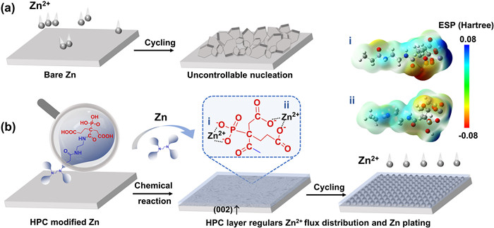
Schematic illustration of Zn planting behaviors on (a) the bare Zn and (b) HPC@Zn anode.
Hyperbranched polyamidoamine protective layer with phosphate and carboxyl groups for dendrite-free Zn metal anodes
Xinxiu Yan , Xizhe Huang , Yangyang Liu , Weishang Jia , Hualin Chen , Qi Yao , Tao Chen

Zinc metal featuring low cost, high capacity (820 mAh/g), low potential (−0.762 V vs. the standard hydrogen electrode), and environmental benignity is a promising anode material for aqueous Zn-based batteries in energy storage devices [1]. However, the Zn metal anodes still undergoes several critical challenges, such as uncontrollable Zn dendrite growth, spontaneous corrosive reactions and hydrogen evolution, leading to low cycling efficiency and limited lifespan, which limit its large-scale implementation [2]. Among these challenges, Zn dendrites are generated during Zn2+ plating processes mainly because uneven nucleation of Zn and subsequent inhomogeneous Zn deposition. In general, Zn dendrite formation brings loose and porous interface structures, exposing more active sites to accelerate corrosion [3]. Meanwhile, dendrites can detach from the substrate, losing electrical contact and increasing surface resistance. The corrosion reaction will continuously consume freshly deposited Zn, resulting in a low CE and poor cycle performance. And worse than that, dendrites cause short-circuits failure of the battery [4,5].
Up to now, several strategies have been proposed to tackle the dendrite growth and eliminate interfacial parasitic reactions for high electrochemical performance of Zn anodes. Interface modification by introducing surface protective coatings or chemical reactions is an efficient strategy for suppressing dendrites growth and enhancing the stability of Zn anode [6,7]. Such as carbon-based layer [8,9], inorganic materials [10-12], metal-organic framework [13,14] and polymer [15-17] have been investigated to modify the Zn anodes. Reasonable design of the coating structure also plays a very important role in realizing the interface layer with functions such as free-dendrites, dynamic adaptability and rapid Zn2+ migration [18,19].
In addition, studies found that the high lattice matching between interfacial layer and Zn deposits, ensures a heterogeneous interfacial region in the early deposition stage, thus it could induce Zn deposition along the (002)Zn plane and achieve a dendrite-free Zn metal anode, such as direct surface coating of halogenated Ti3C2 MXenes (000l) [20], AgZn3 (002) [21] and GO (002) [22]. By using chemical reaction, H3PO4 [23,24] and phytic acid [25] are selected to etch Zn anode to regulate (002)Zn plane and further form a functional zinc compounds layer covering on the Zn surface. More exposed (002)Zn crystal texture could improve Zn deposition behavior and exhibit superior corrosion resistance, due to the surface charge density and lower electrochemical activity [24,26]. Such additives facilitate in the formation of Zn2+-conducting solid electrolyte interphase (SEI) and bonding towards Zn substrate. However, the artificial coating layer may be damaged and exfoliated at a high areal capacity due to the inherent fragility of inorganic composition, leading to further formation of Zn dendrite and the potential risk of corrosion during the tripping and plating process. Therefore, it is necessary to design a zinc compounds-polymer protective architecture with rich binding sites that homogenizes the charge distribution for the uniform Zn deposition and enables the (002)Zn epitaxial growth over long-term cycles.
Hyperbranched polymers (HBP) is a class of large molecule with higher branched structures, which has a unique branched three-dimensional spherical structure with high solubility [27]. The HBP structure periphery contains a large number of terminal multifunctional groups, exhibiting high adjustability and reactivity [28,29]. At the same time, it has outstanding adsorption properties, low viscosity and well compatibility, promoting the HBP molecule to have good adsorption on the metal surface [30].
In this work, we propose to introduce bifunctional groups of phosphate and carboxyl as binding sites and synthesize them on the terminal groups of HBP. An interfacial functional layer of 2-phosphate-1,2,4-butane tricarboxylic acid (PBTCA) modified hyperbranched polyamidoamine has been constructed (marked as HPC). The terminal carboxyl and phosphate functional groups of HPC can react with Zn and adhere tightly to the Zn anode via a facile surface chemistry, yielding a salt-polymer complexes modified Zn anode (HPC@Zn). Specifically, the obtain phosphates and carboxylate of HPC could play a role in effective preservatives for avoiding Zn metal corrosion. Moreover, the chemical reaction of Zn metal using HPC leads to preferential exposure of (002)Zn plane that regulars uniform Zn deposition. The skeleton structure of HPC could easily regulate Zn2+ flux on substrate. Benefiting from the above, the symmetrical cells assembled with the HPC@Zn anode showed an improved cycling stability over 1200 h for a high deposition capacity of 4 mAh/cm2. demonstrating significant potential for application in practice.
For the bare Zn, the inhomogeneous distribution of Zn2+ flux and electrical field at the electrode-electrolyte interface induces the Zn2+ to form rough and non-uniform deposition, resulting in the growth of Zn dendrites (Fig. 1a). However, as shown in Fig. 1b, the molecule structure of HPC has abundant phosphate and carboxyl groups with moderate acidity. When Zn is soaked into the HPC solution (30 wt%), the acid groups can react with it to generate RZnPO4 and R(COO)2Zn (R represents the skeleton structure of HPC) layer that effectively adhere on the Zn surface. In caparison to the initial structure, the electron clouds become richer after structural change i (RZnPO4) and ii (R(COO)2Zn) respectively, presenting enhanced interaction with Zn2+ as a redder color in the electrostatic potential (ESP) calculation. Accompany, HPC layer is formed due to the selective react on Zn metal, resulting in exposure more (002)Zn crystal plane. The surface-preferred (002)Zn crystal plane can induce the parallel growth of Zn metal for effectively resisting the corrosion and stabilizing electrode/electrolyte interface in aqueous electrolyte.
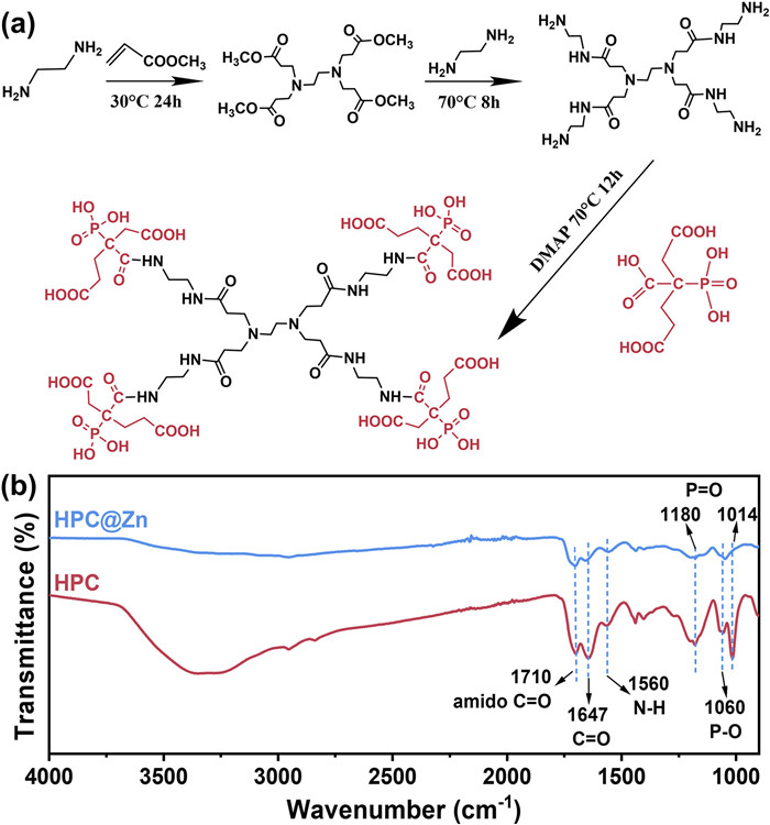
Firstly, the synthesis route of HPC is shown in Fig. 2a and the detail experimental process presented in the experiment section of Supporting information. The FTIR spectra of HPC and HPC@Zn surface are shown in Fig. 2b. The absorption peak at 1710 cm−1 is attributed to the C═O stretching vibration of amide. And the absorption peak at 1647 cm−1 and 1560 cm−1 are assigned to the stretching vibration of C═O and N—H of secondary amide, respectively. In addition, the stretching and bending vibration of the P═O bond is found at 1180 cm−1 and 1014 cm−1 and P-O bond is at 1060 cm−1. These absorption peaks indicate the successfully synthesize of HPC. And simultaneously, HPC with the phosphate and carboxyl functional groups can be also demonstrated by 1H NMR, 13C NMR and 31P NMR spectra in Figs. S1-S3 (Supporting information). After a facile surface chemistry of phosphate and carboxyl functional groups with Zn metal, the absorption peaks of C═O, N—H, P═O and P–O bonds are also found in HPC@Zn surface, which indicates the contained RZnPO4 and R(COO)2Zn salt-polymer complexes effectively attached to Zn metal.
XPS spectra detected of the distribution of C, N, P and Zn on the surface composition. In Figs. 3a-c, the signal peak of N 1s has been found, P 2p signal appear at 133.3 eV. In addition, the increased content of C—C/C—H, C—O, and C═O structures also indicate the presence of surface covering layer (Fig. 3d). Moreover, compared with bare Zn, Zn 2p peak of HPC@Zn undergoes a high shift (Fig. 3e), which may be because of the Zn2+ in the RZnPO4 and R(COO)2Zn. At the same time, the reduced Zn 2p peak intensity of HPC@Zn illustrates that the HPC layer is strongly adhered to Zn surface through the strong interaction between acidic function groups (carboxyl group, phosphate group) and Zn. XPS depth measurements were conducted to investigate the thickness of the surface coating. As shown in Figs. S4a and b (Supporting information), when the etching depth reached 40 nm, nearly no signal in the binding energy of P 2p could be observed. For Zn 2p, the peak strength gradually increases and the bulk Zn is exposed. Depth profiling spectra reveals the binding energy of the salt-polymer complexes with a thickness layer of 30–40 nm.
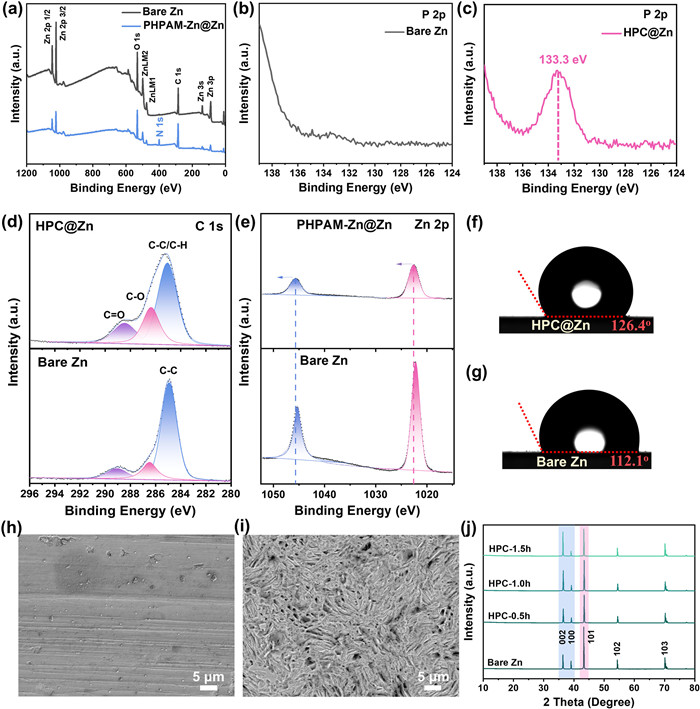
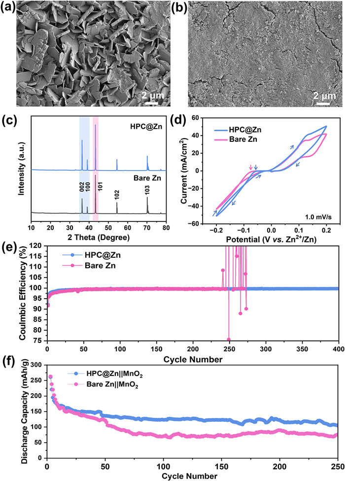
In addition, we studied the surface wetting ability of HPC@Zn electrodes with pure water by the contact angel meter (Figs. 3f and g). The contact angle of HPC@Zn is slightly higher than that of bare Zn, resulting from the hydrophilic surface after chemical treatment. The main reason for this is the formation of porous structures on the surface. Surface morphology of Zn anode greatly influences the Zn2+ distribution and transport. From the SEM images, bare Zn shows a uniform and smooth surface (Fig. 3h). After chemical treatment with HPC for 1.0 h, irregular porous structure is formed (Fig. 3i), leading to increased surface area for a uniform Zn2+ flux on the Zn surface during the tripping and plating process. Besides, the porous structure exposes more (002)Zn crystal plane, which is conducive to the growth of Zn along the horizontal direction. As such, HPC@Zn and bare Zn are characterized by XRD, and the diffraction peaks correspond to PDF#87–0713 of Zn metal (Fig. 3j). We observe that the relative intensities of (002)Zn diffraction obviously increase with the prolongation of reaction time, as illustrated by XRD results of samples treated by HPC solution for 0.5, 1.0 and 1.5 h. Carboxyl and phosphate groups can selectively remove (100) crystal planes because they have lower binding energy between Zn atoms and high surface energy.
To further investigate the corrosion behavior of aqueous electrolyte to Zn anode, bare Zn and HPC@Zn electrodes were immersed into 3 mol/L ZnSO4 aqueous solution for 7 days and the surface morphology changes were observed. HPC@Zn electrode has smoother surface than bare Zn in Figs. S5a and b (Supporting information), and more bubbles can be seen during this process (Fig. S5c in Supporting information). Furthermore, the corrosion behavior is investigated by linear polarization experiments at a sweeping rate of 1.0 mV/s. Fig. S5d (Supporting information) shows the measure Tafel plots of bare Zn and HPC@Zn. The corrosion current of HPC@Zn (1.778 mA/cm2) is slight lower than that of bare Zn (3.236 mA/cm2), indicating lower corrosion rate of HPC@Zn anode.
We tested the symmetrical batteries data of HPC@Zn for different times (marked as HPC@Zn-0.5 h, HPC@Zn-1.0 h, HPC@Zn-1.5 h). Fig. S6 (Supporting information) displays the voltage profiles at the current density of 1 mA/cm2 and with the cycling capacity of 1 mAh/cm2. The symmetric cells with HPC@Zn-1.0 h, HPC@Zn-1.5 h electrodes exhibit cycling lives over 700 h, longer than the 360 h of HPC@Zn-0.5 h electrode, which indicates successful suppression of dendrites as the etching time increases. The morphologies of the deposited Zn were investigated with SEM after 50 cycles. HPC@Zn-1.0 h electrode remains flat, indicating controlled deposition/dissolution behavior. Hexagonal crystals with the (002)Zn plane parallel to the substrate are observed in the SEM image of the cycled HPC@Zn-0.5 h, probably due to insufficient selective reaction and surface morphology. By comparison, HPC@Zn-1.5 h electrode has the longer the soaking time, and the surface shows some aggregated particles and pores but no large dendrites formation. At the same time, we found that the polarization increased with HPC@Zn-1.5 h electrode, and it is more obvious at high current density. Thus, Zn foils soaked for one hour are used to achieve a balance between crystal surface and morphology for a comprehensive improvement of the electrochemical performance of the HPC@Zn electrode. Additionally, from the cross-sectional SEM images of the HPC@Zn before and after 10 cycles (Fig. S7 in Supporting information), the morphology of the deposited Zn on HPC@Zn is denser and homogeneous. These results corroborate the capability of the coating to primitively guide uniform Zn deposition.
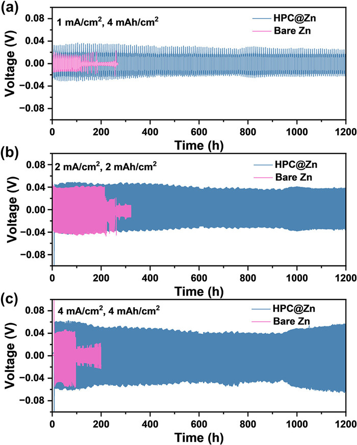
To evaluate the long-term stability of HPC@Zn anode under a high depositon capacity of 2 and 4 mAh/cm2, galvanostatic charging/discharging performance was measured in bare Zn||Zn and HPC@Zn||HPC@Zn symmetric cells at various current densities. As exhibited in Fig. 4, HPC@Zn cells achieve much longer cycle life, displaying a stable cycling performance for 1200 h at a current density and an areal capacity of 1 mA/cm2 and 4 mAh/cm2, 2 mA/cm2 and 2 mAh/cm2, 4 mA/cm2 and 4 mAh/cm2. Whereas, bare Zn showed an abrupt failure and short-circuit due to Zn dendrites formation at about 130, 220 and 100 h, respectively. Such enhancement in the cycling performance of HPC@Zn anode is mainly due to synergistic effect of HPC coating morphology and the preferential exposure of (002)Zn crystal plane. After plating/stripping for 50 cycles, HPC@Zn anode has more uniform surface from the digital photo of Fig. S8 (Supporting information).
The SEM results of cycled electrodes also supported the preferential plane deposition shown in the XRD analysis. As shown in Fig. 5a, protuberant Zn dendrites and resultant sharp structure were observed on the cycled bare Zn anode. Conversely, the cycled HPC@Zn anode obtained a very clean and uniform surface (Fig. 5b), confirming the role of HPC in regulating Zn deposition and plane-oriented growth. After long-term Zn plating/stripping process, the preferential deposition of (002)Zn planal-oriented Zn was still sustained (Fig. 5c). The increased (002)Zn plane and decreased (100)Zn plane is illustrated by XRD patterns of cycled HPC@Zn anode. During the initial nucleation process, the salt-polymer complex on HPC@Zn further acts as zincophilic sites compared with the bare Zn surface to guide uniform Zn nucleation and deposition. Fig. 5d shows CV curves of the symmetrical cells. During the cathodic scan, the Zn2+ reduction overpotential of HPC@Zn is the lower than bare Zn, which indicates an effectively reduced energy barrier and regulates the distribution and migration Zn2+ for deposition. CV profiles at different scan rates of the symmetrical HPC@Zn cell also demonstrate better electrochemical kinetics as indicated by smaller polarization and more intensive peak currents by virtue of higher interfacial charge transfer (Fig. S9 in Supporting information). Moreover, coulombic efficiency (CE) plots of Zn||Cu half-cells using HPC@Zn anodes showed stable cycling over 400 cycles with a high average CE of 99.65% (Fig. 5e), indicating that HPC treatment mitigated dendrite growth and side reaction. In contrast, the bare Zn||Cu half-cell suffers from a short circuit at the 237th cycle due to the dendrite penetrating the separator, resulting in cell failure. To demonstrate the practicality of Zn anodes, Zn||MnO2 full cells have been assembled and tested using bare Zn and HPC@Zn anodes. As shown in Fig. 5f, the cell with HPC@Zn anode exhibits a specific capacity of 261 mAh/g at 0.2 A/g. After 100 cycles, the HPC@Zn||MnO2 cell still retains a remarkable specific capacity of 123.5 mAh/g, corresponding capacity retention of 47.3%). However, the cell with bare Zn as the anode behaves a rapid capacity decline at the 30 cycles, and the capacity is only 70.7 mAh/g with a low-capacity retention of 26.9% after 100 cycles, which can be ascribed to the formation of dendrites and accumulation of non-conductive byproducts. Long cycling tests for 250 cycles, HPC@Zn||MnO2 cell still achieved capacity retention of 40%, showing excellent anodic protection and long-cycle stability. The rate performance of the HPC@Zn||MnO2 and bare Zn||MnO2 cells have been show in Fig. S10 (Supporting information), HPC@Zn||MnO2 exhibits a better rate performance. The discharge capacity of the HPC@Zn cell is higher than that of bare Zn at different current densities.
In summary, a facile and effective surface chemistry strategy is developed to optimize the Zn metal electrode, by regulating the surface with a phosphate and carboxyl groups modified HPC layer. The obtained HPC@Zn anode surface endowed more favorable skeleton structure of HPC contained, which is conducive to uniform the Zn2+ flux distribution and regulate the Zn deposition/dissolution behaviors. Furthermore, HPC enables a dendrite-free Zn deposition with the preferential exposure of (002)Zn plane due to the reaction between terminal carboxyl and phosphate functional groups and Zn metal, generating RZnPO4 and R(COO)2Zn salt-polymer complexes that effectively adhere on the Zn surface. As a result, the HPC@Zn electrodes exhibit superior electrochemical performance comparing with bare Zn. HPC@Zn electrode ensures reversible Zn stripping/plating for over 1200 h at the current density of 4 mA/cm2, and a high deposition capacity of 4 mAh/cm2. And the HPC@Zn||MnO2 cell still retains a remarkable specific capacity of 123.5 mAh/g after 100 cycles. This work has provided potential application for employing diverse terminated groups (such as carboxyl or phosphate) modified HBP to high performance Zn metal batteries.
The authors declare that they have no known competing financial interests or personal relationships that could have appeared to influence the work reported in this paper.
This work was financially supported by the National Natural Science Foundation of China (No. 22209134) and the Southwest Minzu University Research Startup Funds (No. RQD2021097).
Supplementary material associated with this article can be found, in the online version, at doi:
S.W.D. Gourley, R. Brown, B.D. Adams, et al., Joule 7 (2023) 1415–1436. doi: 10.1016/j.joule.2023.06.007
X.H. Zheng, T. Ahmad, W. Chen, Energy Storage Mater. 39 (2021) 365–394. doi: 10.1016/j.ensm.2021.04.027
J.Y. Yin, X. Feng, Z.H. Gan, et al., Energy Storage Mater. 54 (2023) 623–640. doi: 10.1016/j.ensm.2022.11.006
T. Wang, J.M. Sun, Y.B. Hua, et al., Energy Storage Mater. 53 (2022) 273–304. doi: 10.1016/j.ensm.2022.08.046
Y.H. Zou, X.Z. Yang, L. Shen, et al., Energy Environ. Sci. 15 (2022) 5017–5038. doi: 10.1039/d2ee02416k
J.F. He, Y.C. Tang, G.G. Liu, et al., Adv. Energy Mater. 12 (2022) 2202661. doi: 10.1002/aenm.202202661
S.Z. Zhang, M.H. Ye, Y.F. Zhang, et al., Adv. Funct. Mater. 33 (2023) 2208230. doi: 10.1002/adfm.202208230
Z.B. Zhou, Y.M. Zhang, P. Chen, et al., Chem. Eng. Sci. 194 (2019) 142–147. doi: 10.25103/jestr.126.18
Y.T. Hao, J.H. Zhou, G.L. Wei, et al., ACS Appl. Energy Mater. 4 (2021) 6364–6373. doi: 10.1021/acsaem.1c01306
J. Han, H. Euchner, M. Kuenzel, et al., ACS Energy Lett. 6 (2021) 3063–3071. doi: 10.1021/acsenergylett.1c01249
H.B. He, H. Tong, X.Y. Song, et al., J. Mater. Chem. A 8 (2020) 7836–7846. doi: 10.1039/d0ta00748j
C.B. Deng, X.S. Xie, J.W. Han, et al., Adv. Energy Mater. 30 (2020) 2000599. doi: 10.1002/adfm.202000599
M. Gopalakrishnan, S. Ganesan, M.T. Nguyen, et al., Chem. Eng. J. 457 (2023) 141334. doi: 10.1016/j.cej.2023.141334
M.Q. Liu, L.Y. Yang, H. Liu, et al., ACS Appl. Mater. Interfaces 11 (2019) 32046–32051. doi: 10.1021/acsami.9b11243
F. Zhang, C.G. Wang, J. Pan, et al., Mater. Today Energy 17 (2020) 100443. doi: 10.1016/j.mtener.2020.100443
M.S. Zhu, J.P. Hu, Q.Q. Lu, et al., Adv. Mater. 33 (2021) 2007497. doi: 10.1002/adma.202007497
Z.M. Zhao, J.W. Zhao, Z.L. Hu, et al., Energy Environ. Sci. 12 (2019) 1938–1949. doi: 10.1039/c9ee00596j
Z.K. Guo, L.S. Fan, C.Y. Zhao, et al., Adv. Mater. 34 (2022) 2105133. doi: 10.1002/adma.202105133
A. Chen, C.Y. Zhao, J.Z. Gao, et al., Energy Environ. Sci. 16 (2023) 275. doi: 10.1039/d2ee02931f
X.L. Li, M. Li, K. Luo, et al., ACS Nano 16 (2022) 813–822. doi: 10.1021/acsnano.1c08358
H.F. Lu, Q.Z. Jin, X. Jiang, et al., Small 18 (2022) 2200131. doi: 10.1002/smll.202200131
J. Cao, D.D. Zhang, C. Gu, et al., Adv. Energy Mater. 11 (2021) 2101299. doi: 10.1002/aenm.202101299
T.T. Su, K. Wang, B.Y. Chi, et al., EcoMat 4 (2022) e12219. doi: 10.1002/eom2.12219
X. Wang, J.P. Meng, X.G. Lin, et al., Adv. Energy Mater. 31 (2021) 2106114.
H. Fu, Q. Wen, P.Y. Li, et al., J. Energy Chem. 73 (2022) 387–393. doi: 10.1016/j.jechem.2022.05.033
M. Zhou, S. Guo, J.L. Li, et al., Adv. Mater. 33 (2021) 2100187. doi: 10.1002/adma.202100187
Y. Ahmadi, K.H. Kim, Adv. Colloid Inter. Sci. 302 (2022) 102633. doi: 10.1016/j.cis.2022.102633
S.F. Chen, Z.J. Xu, D.H. Zhang, Chem. Eng. J. 343 (2018) 283–302. doi: 10.1016/j.cej.2018.03.014
A. Kavand, N. Anton, T. Vandamme, et al., J. Controlled Release 321 (2020) 285–311. doi: 10.1016/j.jconrel.2020.02.019
E. Pedziwiatr-Werbicka, K. Milowska, V. Dzmitruk, et al., Eur. Polym. J. 119 (2019) 61–73. doi: 10.1016/j.eurpolymj.2019.07.013

Figure 1 Schematic illustration of Zn planting behaviors on (a) the bare Zn and (b) HPC@Zn anode.

Figure 2 (a) Synthetic schematic diagram of HPC. (b) The FTIR spectra of HPC and HPC@Zn.

Figure 3 The XPS spectra of (a) survey, (b) P 2p of bare Zn, (c) P 2p of HPC@Zn, (d) C 1s and (e) Zn 2p. Contact angles of (f) HPC@Zn and (g) bare Zn. SEM images of (h) bare Zn and (i) HPC@Zn. (j) XRD patterns of the Zn foils treated by HPC solution (30 wt%) for 0.5, 1.0 and 1.5 h.

Figure 4 Cycling performance of symmetric cells for bare Zn and HPC@Zn with a current density and an areal capacity of (a) 1 mA/cm2 and 4 mAh/cm2, (b) 2 mA/cm2 and 2 mAh/cm2, (c) 4 mA/cm2 and 4 mAh/cm2.

Figure 5 SEM images of (a) bare Zn and (b) HPC@Zn electrodes after 50 cycles. (c) Corresponding XRD patterns of cycled Zn and HPC@Zn electrodes. (d) CV curves of the symmetrical cells with the HPC@Zn and bare Zn at a scan rate of 1.0 mV/s. (e) Coulombic efficiencies of the Zn||Cu cell at 2 mA/cm2 for 2 mAh/cm2. (f) The cycling performance of the HPC@Zn||MnO2 and bare Zn||MnO2 under a current density of 0.2 A/g.

 扫一扫看文章

扫一扫关注我们
 DownLoad:
 下载:
下载:
 下载:
下载: