Scheme 1.
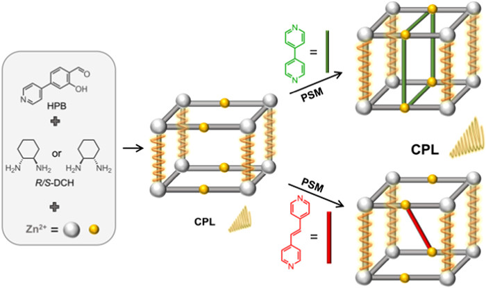
Schematic representation for synthesis and post-synthetic installation of CPL-active MOFs.
Amplified circularly polarized luminescence of chiral metal-organic frameworks via post-synthetic installing pillars
Xue-Zhi Wang , Yi-Tong Liu , Chuang-Wei Zhou , Bei Wang , Dong Luo , Mo Xie , Meng-Ying Sun , Yong-Liang Huang , Jie Luo , Yan Wu , Shuixing Zhang , Xiao-Ping Zhou , Dan Li

Circularly polarized luminescence (CPL) materials have exhibited widespread potential applications in the field of three-dimensional (3D) displays [1], information storage and encryption [2], asymmetric synthesis [3], and biological probes [4], and attracted intensive research interest of scientists. Compared with the method of using a linear polarizer and a quarter-wave plate, the chiral materials can directly emit right- or left-CPL, thus avoiding a loss of light intensity [5]. Many CPL-active materials have been developed, generally focusing on chiral lanthanide complexes [6-8], small molecules [9,10], polymers [11], liquid crystals [12], and supramolecular assembly systems [13,14]. However, it remains challenging to maximize both the luminescence dissymmetry factor (glum) and photoluminescence quantum yield (PLQY) simultaneously due to the inherent trade-offs.
As typical porous crystalline materials, metal-organic frameworks (MOFs) constructed from metals and organic linkers have attracted great attention due to their tunable pores, beautiful structures, and potential applications [15-18]. MOFs can be both luminescent and chiral and are ideal materials for exploring CPL functions. MOFs may offer an elegant solution to overcome the challenge of trade-offs between PLQY and glum [19-21]. The strategies for obtaining CPL-active MOFs mainly involve decorating organic luminophores on chiral linkers and incorporating luminescent auxiliary ligands into the framework [22-28]. Although a series of CPL-active MOFs have been reported, the development of MOF materials with high CPL performance is still a big challenge [29,30].
Post-synthetic modification (PSM) of MOFs is a useful technique for preparing new MOFs, which can usually enhance the performance of the parent MOFs [31-34]. The inclusion of various guests into the cavities of MOFs has been demonstrated to be a significant strategy of PSM. The guest will enhance the CPL performance of the parent MOFs [35-37]. For example, the γ-cyclodextrin MOFs with chiral voids exhibited better CPL performance after encapsulation of dye molecules [38,39]. Zang and co-workers synthesized a pair of crystalline enantiomeric (P)-(+)/(M)-(−)-EuMOF⊃MAPbX3 adducts, in which achiral MAPbBr3 perovskite nanocrystals were embedded by chiral MOFs [40]. The chiral adducts showed multiple responsive CPL properties upon a diversity of external stimuli including chemicals and temperatures. The installation of a secondary organic linker into the pre-determined sites of the parent MOF is a useful PSM strategy to functionalize the MOFs [41-44]. However, limited examples have been reported for chiral MOFs by using this PSM strategy, especially for boosting the CPL performance of MOFs.
Herein, we report a pair of chiral MOFs, {[Zn2(R/S-L)(H2O)3](NO3)2}n (R/S-1, R/S-H2L=6,6′-[(1R/S, 2R/S)−1,2-cyclohexanediylbis(nitrilomethylidyne)]bis[3-(4-pyridinyl)phenol]), which are synthesized via the subcomponent self-assembly of 2–hydroxy-4-(pyridin-4-yl)benzaldehyde (HPB), chiral 1,2-diaminocyclohexane (R/S-DCH), and Zn2+ ions under solvothermal conditions (Scheme 1). MOFs R/S-1 feature 3D structures with acs topology and have open metal sites and channels for post-synthetic modification. The organic ligands 4,4′-bipyridine (bpy) and 1,2-di(4-pyridyl)ethylene (dpe) were employed as the pillars for the PSM of R/S-1. After post-synthetic installing pillars, the glum (±1.5 × 10⁻³) and PLQY (4.4%) of MOFs R/S-1 are amplified to ±3.5 × 10⁻³ and 8.4%, respectively, providing a useful strategy for boosting the CPL performance of MOF materials.
Solvothermal reactions of Zn(NO3)2·6H2O, HPB, and R/S-DCH in a mixed solvent (DMF/EtOH) gave flaky crystals of R/S-1 (for details, see Supporting information). Single-crystal X-ray diffraction revealed that both R-1 and S-1 crystallize in a chiral orthorhombic space group P212121. Hence the structural description is restricted to the R-1. As shown in Fig. 1a, the asymmetric unit of R-1 contains four Zn2+ ions, two R-L, and six terminal water molecules. There are three kinds of Zn2+ ions with different coordination environments. Zn1 and Zn2 atoms have pentacoordinate environments and adopt two different distorted square pyramidal geometries. Zn1 coordinates with two nitrogen atoms (N1 and N2) and two oxygen atoms (O1 and O2) from one R-L and one nitrogen atom N3 from another ligand. The bond distances of Zn–O and Zn–N are in the range of 2.010(6)–2.053(6) Å and 2.021(7)–2.071(8) Å, respectively. The formed metallosalen ligands (denoted as R-ZnL) bridge each other to construct an infinite right-handed 21 helical chain (Fig. 1b and Fig. S1a in Supporting information). The helical chains extend to form a two-dimensional (2D) layer substructure in the bc plane with Zn3 as connecting atoms (Fig. S1b in Supporting information). The Zn3 has a distorted octahedral geometry by coordinating with four oxygen atoms of two adjacent R-ZnL and two oxygen atoms of terminal water molecules. The bond distances of Zn3–O are in the range of 2.086(5)–2.090(5) Å. In addition, the Zn4 atom adopts a similar octahedral geometry surrounded by four water-oxygen atoms (Zn4–O distances are 1.97(2)–2.058(17) Å) and two nitrogen atoms (Zn–N bonds are 2.124(10)–2.131(7) Å) from two R-L ligands. Finally, the 2D substructures are connected to each other through Zn4 atoms, forming a chiral 3D framework structure (Fig. 1c and Fig. S1c in Supporting information). It is worth noting that four adjacent Zn4 atoms form a parallelogram-shaped cavity with lengths of ca. 11.0 and 14.4 Å, offering anchorable sites and chiral pockets (Fig. 1d). The S-1 shows the enantiomeric structure features to R-1 (Fig. S2 in Supporting information). There are two types of channels along the b and c axes, which are filled with solvent molecules and NO3− anions (Fig. S3 in Supporting information). PLATON calculations revealed the accessible voids of R-1 and S-1 are 4515 Å3 (51.1%) and 4329 Å3 (47.6%) per unit cell, respectively. From the perspective of topological analysis, simplifying the dimer substructure containing two R-L ligands as a 6-connected node (Fig. S4 in Supporting information), the underlying topology of R-1 and S-1 can be obtained as the acs net with minimal transitivity [11] and a point symbol of {49.66} (Fig. 1d) [45,46].

We employed powder X-ray diffraction (PXRD) to test the phase purity of R/S-1. As shown in Fig. S5 (Supporting information), the experimental PXRD patterns of R/S-1 were well consistent with their simulated patterns, suggesting that the samples of R/S-1 were pure phase. Thermogravimetric analysis (TGA) revealed that R/S-1 was stable up to around 300 ℃ under N2 atmosphere (Fig. S6 in Supporting information). We also checked the chemical stabilities of R-1. The PXRD studies revealed that the crystallinity of R-1 is retained after soaking in low-boiling point organic solvents, while the stability in high-boiling point organic solvents and water is poor at room temperature for 24 h (Fig. S7 in Supporting information).
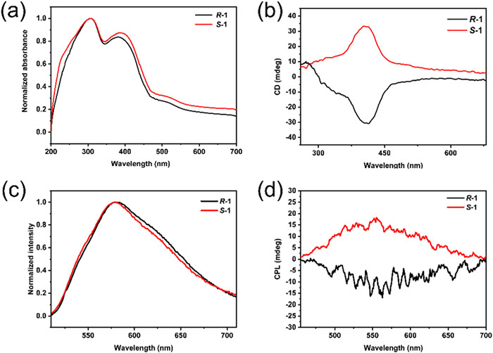
The solid-state UV–vis absorption spectra of R/S-1 are identical, showing main absorption peaks at 306 and 388 nm, which can be ascribed to π–π* transition of R/S-L and the charge transfer of the ligand-to-metal (LMCT) (Fig. 2a), respectively [47]. The solid-state dichroism (CD) spectrum of R-1 exhibited a negative Cotton effect at λmax = 413 nm, while a positive mirror-image spectrum of S-1 was observed, confirming the optical activity of bulk materials (Fig. 2b). The absolute values of absorptive asymmetric factor (gabs) of MOFs R/S-1 were about ±5.6 × 10⁻⁴ (Fig. S8 in Supporting information). Upon being excited at 480 nm, both R-1 and S-1 emitted yellow light at approximately 578 nm (Fig. 2c and Fig. S9 in Supporting information). The photoluminescence of R/S-1 is red-shifted compared with those of the reported R/S-ZnL (at 560 nm) [48]. The photoluminescence quantum yields of R/S-1 are determined to be 4.4% by diffuse light within an integrating sphere (Table S2 in Supporting information). The decay lifetime of R-1 and S-1 are 2.14 and 2.19 ns at room temperature, respectively, suggesting that they have fluorescent emission characteristics. Their fluorescent emissions probably originate from intra-ligand charge transfer (ILCT) and/or LMCT transitions [49]. Furthermore, we investigated the CPL behaviors of R/S-1. As shown in Fig. 2d, the mirror image CPL signals of R-1 (negative) and S-1 (positive) were observed at around 560 nm with glum = ±1.5 × 10⁻³. The glum values are higher than that of the reported mononuclear Zn2+ complex of R-HL (−6.0 × 10⁻⁴) [49]. The amplification of CPL is inseparable from the well-ordered helical arrangement of the chiral emitters [50,51].
As shown in Fig. 1c, Zn4 atoms in R-1 coordinated to terminal water can serve as binding sites for an organic ligand. The distances between two adjacent Zn4 atoms are 11.0 and 14.4 Å, respectively. Thus, when bidentate organic ligands with suitable sizes were judiciously selected, MOFs R/S-1 could be modified by installing organic pillars. Two pyridyl-terminated linkers with different lengths were selected (Fig. 3a), including 4,4′-bipyridine (bpy) and 1,2-di(4-pyridyl)ethylene (dpe). The lengths of two linkers between the pyridyl-nitrogen atoms are ~7.66 and 10.06 Å, respectively, which is a good match for the required length (~11.76 and 14.35 Å) when two coordination bonds (around 2.0 Å) are calculated.
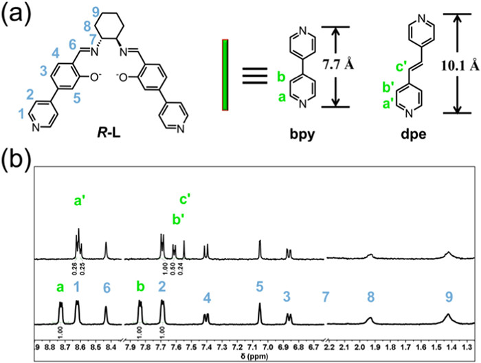
We soaked the single crystalline samples of R/S-1 in ethanol solutions of bpy and dpe at room temperature for 72 h to obtain post-modified MOFs (denoted as R/S-2bpy and R/S-2dpe, respectively). To confirm the successful PSM of R/S-1, the 1H NMR was employed. As shown in Fig. 3b, the new chemical shifts belonging to bpy and dpe were observed, suggesting they were installed in MOFs R/S-1 successfully. The molar ratios between R-L and bpy in R/S-2bpy were 1:1, which were calculated by using the peak integration. These results suggested that all water molecules binding on Zn4 atoms were replaced by bpy ligands. For R-2dpe, the ratio of the R-L to dpe linker was 2:1, suggesting that only half of the water molecules of Zn4 were replaced with dpe ligands. These results are in agreement with their structural features. In R/S-1, for each Zn4 atom, four adjacent Zn4 atoms are close to it with a distance of about 11.8 Å, which is suitable for installing a bpy pillar (7.66 Å). Therefore, four water molecules on each Zn4 can be replaced by pyridyl groups of bpy, leading to a 1:1 ratio between R/S-L and bpy. On the other hand, for installing dpe ligand (10.06 Å), the distance between two adjacent Zn atoms requires about 14.0 Å. For each Zn4 atom, only another two Zn4 are with a distance close to 14.0 Å, which offers a "pocket" for dpe ligands. Not like bpy ligand, the pyridyl groups of dpe only replace two water molecules of Zn4, giving a ratio of 2:1 between R/S-L and dpe.
Further, the electronic structure change after post-synthetic installation was investigated by using X-ray photoelectron spectroscopy (XPS). The XPS spectrum of the pristine MOF R-1 showed the presence of C 1s, O 1s, N 1s, and Zn 2p, respectively (Fig. S11 in Supporting information). As shown in Fig. S12 (Supporting information), the high-resolution N 1s spectra showed a gradual increase of pyridinic N species at 398.98 eV (64.94% and 74.07% for R-1 and R-2bpy, respectively) after the insertion of ligand bpy [52,53]. It is worth noting that there is a negative shift in the binding energy of Zn 2p1/2 and Zn 2p3/2 from 1045.6 eV to 1045.2 eV and 1022.1 eV to 1021.9 eV, respectively after the post-synthetic installation. This shift indicates an increase in electron density around Zn atoms due to the lower electron affinity of pyridinic N species (Fig. S13 in Supporting information) [54]. The XPS results further support that the post-synthetic installation is successful.
After the installation of the pillars, the quality of crystals R/S-2bpy and R/S-2dpe was poor. Their PXRD was measured. The PXRD patterns were close to that of parent R/S-1 and R/S-1, suggesting the main framework structure was not changed after the installation of bpy and dpe pillars. Taking R-2bpy as an example, the crystal structure was analyzed by PXRD experiments combined with theoretical simulations performed in the Materials Studio software package (for details, see Supporting information). The PXRD pattern of R-2bpy exhibits a slight shift to a lower angle from 5.1° to 4.9° corresponding to the [100] reflection, suggesting the framework of R-2bpy has a slightly bigger unit cell after the insertion of additional bpy linkers (Fig. 4a and Fig. S14 in Supporting information). Thus, Pawley refinements of R-2bpy yield the optimized unit cell parameters of a = 35.9803 Å, b = 17.2145 Å, c = 14.8781 Å, α = 90.8594°, β = 89.8389°, γ = 90.5446°, and the space group of P1, with good residual factors of Rp = 5.03% and Rwp = 7.07%. The negligible difference plot in Fig. 4a suggests that the refined PXRD patterns are in good agreement with the experimental data. As shown in Fig. 4b, the simulated structural model of R-2bpy indicates that the bpy linkers connect with Zn atoms and replace all terminal water molecules. After linker installation, the Zn4 becomes a 6-connected node. The new framework can be simplified as a (6,6)-c net with minimal transitivity [24] and the point symbol of {3.44.57.63}{32.44.56.63} (Fig. S15a in Supporting information).
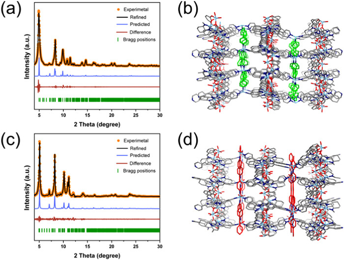
Similarly, Pawley refinements of PXRD patterns of R-2dpe were also performed to give space group of P1 with unit cell parameters of a = 34.8964 Å, b = 17.8539 Å, c = 14.5903 Å, α = 90.1203°, β = 89.7741°, γ = 89.7630°, as well as refinement parameters of Rp = 8.63% and Rwp = 5.90%. The resulting refined PXRD patterns are in good agreement with the experimental data, as confirmed by the negligible difference curve (Fig. 4c). As shown in Fig. 4d, the longer linker dpe ligands are inserted into R-1 to form R-2dpe Two coordinated water molecules of Zn4 atom were replaced with dpe ligands. For topological analysis, the Zn4 atoms can be considered as 4-connected nodes, and the framework of R-2dpe could be treated as a (4,6)-c net with minimal transitivity [23] and the point symbol of {44.510.6}{44.58.63} (Fig. S15b in Supporting information).
The photophysical properties of R/S-2bpy and R/S-2dpe were also studied. As shown in Fig. 5a, the CD spectra of these two MOFs showed a slight red shift between 250 nm and 500 nm. On the other hand, the emission maximum of R/S-2bpy and R/S-2dpe is also slightly red-shifted compared to the R-1 (Fig. S17 in Supporting information), which could be associated with the further extended π−π stacking states by pillars [55]. The Commission Internationale de l'Eclairage (CIE) coordinates are calculated to be (0.52, 0.47) and (0.54, 0.46), respectively (Fig. S18 in Supporting information). Moreover, R-2bpy and R-2dpe show higher quantum yields (8.4% and 6.7%) and shorter lifetimes (0.54 and 0.85 ns) than those of the parent R-1 (4.4%, 2.14 ns). The enhancing quantum yields and shortening lifetime are probably due to the enhancement of the rigidity of the chiral framework, which can reduce the nonradiative decay of the excited state and lead to pronounced fluorescence.
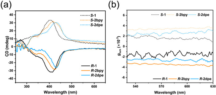
We also further measured the CPL spectra of R/S-2bpy and R/S-2dpe. The R/S-2bpy and R/S-2dpe displayed enlarged mirror image CPL signals (Fig. S19 in Supporting information). The corresponding |glum| of R/S-2bpy was about 3.5 × 10⁻³, which was higher than that of R/S-2dpe (2.7 × 10⁻³) and R/S-1 (1.5 × 10⁻³) (Fig. 5b). These results show that MOFs R/S-2bpy have the best CPL performance among these enantiomeric MOF materials. Thus, the post-synthetic installation of pillars in CPL-active MOFs could facilitate chiral exciton couplings and lead to significantly amplified CPL signals over their assemblies.
In summary, we have successfully synthesized and characterized a pair of enantiomeric 3D MOFs based on the salen ligands through solvothermal subcomponent self-assembly, and they contain chiral chains and feature the acs topology. Their chirality and CPL behaviors were carefully studied. These chiral MOFs contain anchorable sites and pockets for the post-synthetic installation of pillar ligands. 1H NMR, XPS, and X-ray crystallography studies reveal that the pyridyl-terminated linkers (bpy and dpe) can be installed into the chiral MOFs with distinct amounts depending on their molecule size. The pillar ligands rigidify the parent framework and lead to a remarkable enhancement of their PLQYs. The glum values also amplified simultaneously. This work highlights that post-synthetic installation is a powerful approach to enhance the CPL activity of MOFs, which provides a preliminary method to solve the problem of the trade-offs between glum and PLQY in MOF materials. We can anticipate more MOFs with high CPL performance can be prepared by using this useful strategy.
The authors declare no conflict of interest.
This work was financially supported by the National Natural Science Foundation of China (Nos. 21731002, 21871172, 21975104, 22171106, 22301103, 22375075, and 82227802), the Guangdong Major Project of Basic and Applied Research (No. 2019B030302009), Guangdong Natural Science Foundation (No. 2022A1515011937), the Guangzhou Science and Technology Program (Nos. 202002030411, 202201020022), Guangdong Basic and Applied Basic Research Foundation (No. 2022A1515110523), the China Postdoctoral Science Foundation (Nos. 2023T160269, 2023M741374), and Jinan University.
Supplementary material associated with this article can be found, in the online version, at doi:
X. Zhan, F.F. Xu, Z. Zhou, et al., Adv. Mater. 33 (2021) e2104418. doi: 10.1002/adma.202104418
H. Fan, K. Li, T. Tu, et al., Angew. Chem. Int. Ed. 61 (2022) e202200727. doi: 10.1002/anie.202200727
T. Kawasaki, M. Sato, S. Ishiguro, et al., J. Am. Chem. Soc. 127 (2005) 3274–3275. doi: 10.1021/ja0422108
S. Shuvaev, M.A. Fox, D. Parker, Angew. Chem. Int. Ed. 57 (2018) 7488–7492. doi: 10.1002/anie.201801248
J. Kumar, T. Nakashima, T. Kawai, J. Phys. Chem. Lett. 6 (2015) 3445–3452. doi: 10.1021/acs.jpclett.5b01452
B.N. Willis, D. Schnable, N.D. Schley, G. Ung, J. Am. Chem. Soc. 144 (2022) 22421–22425. doi: 10.1021/jacs.2c10364
M. Li, Y. Zhou, J. Li, et al., Chin. Chem. Lett. 35 (2024) 108831. doi: 10.1016/j.cclet.2023.108831
Y. Deng, F. Li, Z. Zhou, et al., Chin. Chem. Lett. 35 (2024) 109085. doi: 10.1016/j.cclet.2023.109085
M. Li, S.H. Li, D. Zhang, et al., Angew. Chem. Int. Ed. 57 (2018) 2889–2893. doi: 10.1002/anie.201800198
Y.P. Zhang, S.Q. Song, M.X. Mao, et al., Sci. China Chem. 65 (2022) 1347–1355. doi: 10.1007/s11426-022-1249-7
M. Xu, G. Li, W. Li, et al., Angew. Chem. Int. Ed. 61 (2022) e202117042. doi: 10.1002/anie.202117042
X. Yang, X. Jin, A. Zheng, P. Duan, ACS Nano 17 (2023) 2661–2668. doi: 10.1021/acsnano.2c10646
G. Park, D.Y. Jeong, S.Y. Yu, et al., Angew. Chem. Int. Ed. 62 (2023) e202309762. doi: 10.1002/anie.202309762
G.H. Chen, Y.P. He, Y. Yu, Q.H. Li, J. Zhang, Sci. China Chem. 66 (2023) 2558–2562. doi: 10.1007/s11426-023-1707-4
H. Furukawa, K.E. Cordova, M. O'Keeffe, O.M. Yaghi, Science 341 (2013) 1230444. doi: 10.1126/science.1230444
H. Zeng, M. Xie, T. Wang, et al., Nature 595 (2021) 542–548. doi: 10.1038/s41586-021-03627-8
W. Gong, Z. Chen, J. Dong, Y. Liu, Y. Cui, Chem. Rev. 122 (2022) 9078–9144. doi: 10.1021/acs.chemrev.1c00740
D. Luo, Y.L. Peng, M. Xie, et al., ACS Appl. Mater. Interfaces 14 (2022) 11547–11558. doi: 10.1021/acsami.2c00118
C. Zhang, S. Li, X.Y. Dong, S.Q. Zang, Aggregate 2 (2021) e48. doi: 10.1002/agt2.48
L.A. Hall, D.M. D'Alessandro, G. Lakhwani, Chem. Soc. Rev. 52 (2023) 3567–3590. doi: 10.1039/d2cs00129b
X.Y. Luo, M. Pan, Coord. Chem. Rev. 468 (2022) 214640. doi: 10.1016/j.ccr.2022.214640
S.M. Chen, L.M. Chang, X.K. Yang, et al., ACS Appl. Mater. Interfaces 11 (2019) 31421–31426. doi: 10.1021/acsami.9b11872
W.L. Shang, X.F. Zhu, T.L. Liang, et al., Angew. Chem. Int. Ed. 59 (2020) 12811–12816. doi: 10.1002/anie.202005703
X.Z. Wang, M.Y. Sun, Z.J. Huang, et al., Adv. Opt. Mater. 9 (2021) 2002096. doi: 10.1002/adom.202002096
H. Jiang, W. Zhang, B. Hou, Y. Liu, Y. Cui, CCS Chem. 5 (2023) 1635–1643. doi: 10.31635/ccschem.022.202202285
L.Z. Sui, Z.B. Jin, G.M. Niu, et al., CCS Chem. (2023) 2215–2224. doi: 10.31635/ccschem.023.202302932
X.Z. Wang, C.W. Zhou, J. Zheng, et al., Adv. Sci. 10 (2023) e2207333. doi: 10.1002/advs.202207333
Y.H. Xiao, P. Weidler, S.S. Lin, et al., Adv. Funct. Mater. 32 (2022) 2204289. doi: 10.1002/adfm.202204289
Z.L. Gong, Z.Q. Li, Y.W. Zhong, Aggregate 3 (2022) e177. doi: 10.1002/agt2.177
A. Zheng, T. Zhao, X. Jin, W. Miao, P. Duan, Nanoscale 14 (2022) 1123–1135. doi: 10.1039/d1nr07069j
S. Mandal, S. Natarajan, P. Mani, A. Pankajakshan, Adv. Funct. Mater. 31 (2020) 2006291.
Y. Hu, X. Zhang, R.S.H. Khoo, et al., J. Am. Chem. Soc. (2023) 13929–13937. doi: 10.1021/jacs.3c03421
Z.J. Li, Y. Ju, J. Qiu, et al., Chem. Commun. 59 (2023) 4958–4961. doi: 10.1039/d3cc00278k
J. Guo, Y. Lian, F.F. Li, et al., Chem Catal. 2 (2022) 2986–3018. doi: 10.1016/j.checat.2022.09.024
T. Zhao, J. Han, X. Jin, et al., Research 2020 (2020) 6452123.
C. Zhang, Z.P. Yan, X.Y. Dong, et al., Adv. Mater. 32 (2020) e2002914. doi: 10.1002/adma.202002914
R. Zhai, Y.H. Xiao, Z.G. Gu, J. Zhang, Nano Res. 15 (2022) 1102–1108. doi: 10.1007/s12274-021-3610-x
L. Hu, K. Li, W. Shang, X. Zhu, M. Liu, Angew. Chem. Int. Ed. 59 (2020) 4953–4958. doi: 10.1002/anie.202000589
M. Kazem-Rostami, A. Orte, A.M. Ortuno, et al., J. Am. Chem. Soc. 144 (2022) 9380–9389. doi: 10.1021/jacs.2c01554
C. Zhang, Z.S. Li, X.Y. Dong, Y.Y. Niu, S.Q. Zang, Adv. Mater. 34 (2022) e2109496. doi: 10.1002/adma.202109496
C.X. Chen, Z. Wei, J.J. Jiang, et al., Angew. Chem. Int. Ed. 55 (2016) 9932–9936. doi: 10.1002/anie.201604023
X. Zhang, B.L. Frey, Y.S. Chen, J. Zhang, J. Am. Chem. Soc. 140 (2018) 7710–7715. doi: 10.1021/jacs.8b04277
J. Pang, S. Yuan, J.S. Qin, et al., J. Am. Chem. Soc. 141 (2019) 3129–3136. doi: 10.1021/jacs.8b12530
B. Zhao, Q. Yang, J.S. Wang, et al., New J. Chem. 45 (2021) 4401–4407. doi: 10.1039/d0nj05866a
O. Delgado-Friedrichs, M. O'Keeffe, Acta Crystallogr. Sect. A: Found. Crystallogr. 59 (2003) 351–360. doi: 10.1107/S0108767303012017
V.A. Blatov, A.P. Shevchenko, D.M. Proserpio, Cryst. Growth Des. 14 (2014) 3576–3586. doi: 10.1021/cg500498k
L.Q. Zuo, T.F. Zhang, Z.K. Zhang, et al., Inorg. Chem. Commun. 99 (2019) 113–118. doi: 10.1016/j.inoche.2018.11.006
B. Wang, X.Z. Wang, D. Luo, X.P. Zhou, D. Li, J. Coord. Chem. 75 (2022) 1670–1678. doi: 10.1080/00958972.2022.2040491
X.Q. Lü, W.X. Feng, Y.N. Hui, et al., Eur. J. Inorg. Chem. 2010 (2010) 2714–2722. doi: 10.1002/ejic.201000100
Y.D. Zhang, S. Yu, B. Han, et al., Matter 5 (2022) 837–875. doi: 10.1016/j.matt.2022.01.001
Y. Sang, J. Han, T. Zhao, P. Duan, M. Liu, Adv. Mater. 32 (2020) e1900110. doi: 10.1002/adma.201900110
Z.H. Sheng, L. Shao, J.J. Chen, et al., ACS Nano 5 (2011) 4350–4358. doi: 10.1021/nn103584t
L. Ci, L. Song, C. Jin, et al., Nat. Mater. 9 (2010) 430–435. doi: 10.1038/nmat2711
R.G. Pearson, lnorg. Chem. 27 (1988) 734–740. doi: 10.1021/ic00277a030
G.J. McManus, J.J. Perry, M. Perry, B.D. Wagner, M.J. Zaworotko, J. Am. Chem. Soc. 129 (2007) 9094–9101. doi: 10.1021/ja071271d

Scheme 1 Schematic representation for synthesis and post-synthetic installation of CPL-active MOFs.

Figure 1 The crystal structure of R-1: (a) Coordination environment of the Zn2+ centers; (b) right-handed (P)21 helical chain along the c axis; (c) view of the 3D framework along the b axis (top) and a parallelogram-shaped cavity by four Zn4 atoms (down), and (d) acs topology. Color codes: Zn, cyan; C, gray; O, red; N, blue; H, omitted.

Figure 2 (a) Solid-state UV–vis absorption spectra, (b) ECD spectra, (c) normalized emission spectra, and (d) CPL spectra of R-1 and S-1.

Figure 3 (a) Ligand R-L and the secondary linkers for the post-synthetic installation in R-1. (b) 1H NMR spectra of the digested samples of R-2dpe (top) and R-2bpy (down).

Figure 4 PXRD characterization of (a) R-2bpy, (c) R-2dpe. Experimental PXRD profile: orange; Pawley-refined profile: black; Bragg positions: green; difference: reddish brown; calculated patterns: blue. 3D structures along the b axis: (b) R-2bpy, (d) R-2dpe.

 扫一扫看文章

扫一扫关注我们
 DownLoad:
 下载:
下载:

 下载:
下载: