Scheme 1.
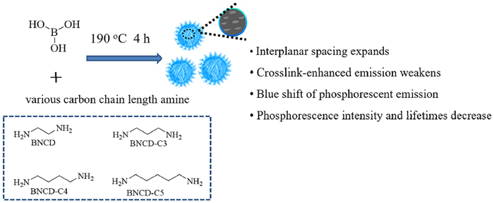
Schematic diagram of the preparation of RTP CDs based on spatial effect.
Spatial effect and resonance energy transfer for the construction of carbon dots composites with long-lived multicolor afterglow for advanced anticounterfeiting
Qian Cheng , Zhiyuan Chen , Lai Hu , Yuwei Song , Senqiang Zhu , Rui Liu , Hongjun Zhu

Advanced anticounterfeiting technologies play an important role in the increasing sophistication of counterfeiting. During the past decades, a variety of anticounterfeiting technologies have been developed, including the recent magnetic response, plasmonic security labels and luminescence printing [1-3]. Among these, luminescence printing offers advantages in easy handling, high-throughput, and facile design. At present, many optical materials have been applied to luminescence printing anticounterfeiting. In particular, room temperature phosphorescent (RTP) materials are considered as an advanced anticounterfeiting material because of their unique optical properties. Conventional organic RTP materials are produced by forming specific structures (i.e., clusters, host-guest compositions, and polymer substrates) or by introducing special groups (i.e., heavy halogens and aromatic aldehydes) [4-7]. However, most of the reported RTP materials were short afterglow lifetime, oxygen sensitivity, and complex synthesis process. As a new class of nanoluminescent carbon material, carbon dots (CDs) have been attracting wide attention owing to easy preparation, biocompatibility, high stability, and excellent optical properties [8-12]. In recent years, CD-based RTP materials have made great progress in long lifetime [13-17]. However, it is difficult to regulate the RTP properties of CDs because the photoluminescence (PL) mechanism is still disputed. Benefited from the theories of quantum dots [18-20], graphene [21,22], and organic molecules [23,24], some PL mechanisms of CDs have been supposed, including carbon core states, surface states, and molecule states. Whereas, there is still not much research on how the spatial effect of precursors affects the RTP properties of CDs. Thus, it is significative to investigate the spatial effect on RTP in CDs.
So far, long-lived CD-based RTP materials can be obtained either by doping carbon dots in solid matrix or by cross-linking enhancement effect (CEE). However, the current CD-based afterglow color is limited to blue and green, which restricts its applications. Förster-resonance energy transfer (FRET) between singlet states of fluorochrome has been widely used to obtain multicolor fluorescent materials [25-27]. Inspired by FRET, we assumed that energy transfer from long-lived triplet states of a donor (CD-based RTP materials) to singlet states (TS-FRET) [28] of a fluorescent acceptor (fluorescent dyes) would be a reliable strategy to obtain CD-based long-lived multicolor afterglow.
In this work, a series of CD-based RTP materials were prepared via melting boric acid (BA) with various carbon chain length amine compounds as precursors (Scheme 1). The introduction of B and N atoms played a significant role in increasing the spin-orbit coupling and promoting the intersystem crossing (ISC) process of CDs to produce more triplet excitons [29-32]. The cross-link of BA and various alkyl diamines can inhibit the non-radiative transition. By regulating the alkyl chain of the diamines compounds, we verified that the spatial effect of the precursor affects the internal spacing of the carbon core, and further changes the energy-level and RTP properties. Meanwhile, inspired by TS-FRET, we employed intense and long-lived phosphorescent CDs as the donor and short-lived fluorescent dyes (Rhodamine 6G (Rh6G) and Rhodamine B (RhB)) as acceptors to develop adjustable wavelength long-lived afterglow. For efficient TS-FRET, we incorporated RTP CDs and fluorescent dyes into amorphous silica via the conventional Stöber synthesis route (Scheme 2). The amorphous silica can not only inhibit non-radiative transitions and prevent water and oxygen from quenching RTP CDs, but also makes the donor and acceptor within Förster distance, which increases the efficiency of TS-FRET. Furthermore, these long-lived multicolor afterglow materials were applied in time-resolved and multiple-color advanced anticounterfeiting.

BNCD, BNCD-C3, BNCD-C4, and BNCD-C5 were prepared via melting BA with various alkyl diamines as precursors. Excitedly, BNCD–BNCD-C5 all exhibited RTP properties. The RTP properties of BNCD, BNCD-C3, BNCD-C4 and BNCD-C5 were further investigated. Fig. 1a and Fig. S1 (Supporting information) show the phosphorescence (Phos) emission spectra and lifetimes of BNCD–BNCD-C5, respectively. As shown in Fig. 1a and Fig. S1, with the increase of alkyl in these diamines precursors, the phosphorescence intensity becomes weaker and the phosphorescence peak shows a blue shift. At the same time, the lifetimes become shorter. These results indicate that the various alkyl diamines as precursors can affect the RTP properties of CDs.

To understand the effect of the precursors on RTP properties, FTIR spectra and XPS were obtained (Figs. 1b-f and Figs. S2–S5 in Supporting information). FTIR spectra of BNCD–BNCD-C5 display characteristic absorption bands of C–B, B–O, and O–H/N–H stretching vibrations [33,34]. The XPS results show that BNCD–BNCD-C5 are mainly composed of carbon, nitrogen, oxygen, and boron. The C 1s band was deconvoluted into three peaks and attributed to C–C/C=C, C–O/C–N and C=O. The N 1s band showed the presence of C–N and N–H. The O 1s band showed two peaks, corresponding to C=O and C–O [35-40]. The B 1s band showed three peaks, corresponding to B–O, C–B and B2O3 [41,42]. The FTIR and XPS results indicate that BA and various alkyl diamines compounds can be cross-linked. The introduction of boron and nitrogen is beneficial to increase the spin-orbit coupling and thus increases ISC to produce more triplet excitons. The cross-link of BA and alkyl diamines compounds inhibited non-radiative transition. Hence, BNCD–BNCD-C5 all exhibited RTP properties. From the XPS results, BNCD–BNCD-C5 showed the same bonding characteristics. This is also consistent with the results obtained using FTIR spectra. But, the RTP properties of BNCD–BNCD-C5 are different. These results indicate that the RTP properties of BNCD–BNCD-C5 are not affected by the functional groups on the surface of CDs. Therefore, we infer that the carbon-core state plays a vital role in phosphorescence properties.
The morphology of BNCD–BNCD-C5 was studied using HR-TEM. These CDs particles showed good dispersion and quasi-spherical morphology (Figs. 2a–d and Fig. S6 in Supporting information). The particle size of BNCD is 1.78 nm and lattice spacing is 0.21 nm. With the growth of the alkyl, the particle size of the CDs increased to 1.85 nm (BNCD-C3), 4.51 nm (BNCD-C4), and 4.55 nm (BNCD-C5) (Fig. S7 in Supporting information), and the lattice spacing increased to 0.24 nm (BNCD-C3), 0.26 nm (BNCD-C4), and 0.30 nm (BNCD-C5). Furthermore, PXRD patterns of BNCD–BNCD-C5 all present two amorphous states (Fig. 2e). The broad peak at 2θ of 23.0° in the PXRD pattern was due to the highly disordered carbon atoms. The peak at around 10° represented the formation of sub-domains with expanded interplanar spacing caused by alkyl [43]. However, with the growth of the alkyl, the other peak of BNCD–BNCD-C5 decreases from 12.8° (BNCD) to 12.3° (BNCD-C3), 11.0° (BNCD-C4), and 10.2° (BNCD-C5). It is well known that d increases as θ decreases under constant n and λ (Bragg's equation: 2dsinθ = nλ) [43,44]. The PXRD results are in good agreement with the HR-TEM. This indicates that the increase of alkyl expands the interplanar spacing of the carbon core, and increases the particle size. Therefore, with the increase of interplanar spacing, CEE weakens, resulting in a decrease in phosphorescence intensity and lifetimes [45-47]. Furthermore, due to the increasing of interplanar spacing, the electron cloud density of the carbon core decreases, which results in a blue shift of phosphorescent emission [48-50].

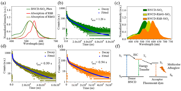
In order to attain long-lived multicolor afterglow materials, we employ intense and long-lived phosphorescent BNCD (38.2% phosphorescence quantum yield) as the donor and the short-lived fluorescent dyes, Rh6G and RhB, as acceptors to develop long-lived multicolor afterglow in a silica encapsulation layer based on TS-FRET. To understand the interaction between the BNCD and Rh6G/RhB, the zeta potential was measured. The zeta potential of the BNCD, Rh6G and RhB in aqueous solution are +0.92 mV, −0.41 mV and −1.09 mV, respectively. This indicates that the BNCD possess a positively charged surface, while the Rh6G and RhB have a negatively charged surface. Thus, they could be combined together through Coulomb interaction. Besides, the full XPS spectrum and EDS of BNCD-SiO2 (Figs. S8a and S9a in Supporting information) demonstrate that the composites contain C, N, O, B and Si elements mainly, where the B is attributed to BNCD and the Si is attributed to silica. As shown in Figs. S8b and c, Figs. S9b and c (Supporting information), the XPS spectra and EDS of BNCD-Rh6G-SiO2 and BNCD-Rh6G-SiO2 also demonstrate that the composites contain mainly C, N, O, B, Cl and Si elements, in which the Cl is attributed to Rh6G/RhB. The Si 2p XPS of BNCD-SiO2, BNCD-Rh6G-SiO2 and BNCD-RhB-SiO2 (Figs. S8d and f in Supporting information) can be deconvoluted into two peaks, which can be attributed to Si−O and C−Si bond. These results suggest that the BNCD have been confined in silica through covalent bonds. As shown in Fig. S10 (Supporting information), HR-TEM clearly shows that the BNCD, Rh6G, or RhB are encapsulated in the amorphous silica, which makes the donor and acceptor within Förster distance to trigger efficient TS-FRET. These results can further confirm that the BNCD and Rh6G/RhB have been confined in silica. Meanwhile, the absorption spectra of Rh6G and RhB and phosphorescence emission spectrum of BNCD-SiO2 were obtained. As shown in Fig. 3a, the absorption bands of Rh6G and RhB overlap well with the phosphorescence emission of BNCD-SiO2 at about 400-670 nm. This indicates that the energy levels of the donor and acceptors are matched [51-53]. When no fluorescent dye is added, BNCD-SiO2 shows an afterglow peak at 520 nm and the lifetime is 1.26 s (Figs. 3b and c) and the phosphorescence quantum yield is 28.8%. As shown in Fig. 3c, when Rh6G or RhB is added, the afterglow peak at 520 nm decreases, and the afterglow peak at 560 nm or 590 nm is enhanced, which is derived from the emission of Rh6G and RhB. The afterglow peaks intensity ratio and afterglow lifetime between 560 nm (Rh6G) or 590 nm (RhB) and 520 nm (BNCD) increased with the increase in Rh6G or RhB concentration (Fig. S11 in Supporting information), indicating that an efficient TS-FRET process occurred between the BNCD and Rh6G or RhB, making the afterglow color change from green to orange (Fig. 4). When the excitation light was turned off, BNCD, BNCD-SiO2, BNCD-Rh6G-SiO2 and BNCD-RhB-SiO2 all exhibited an afterglow that was visible to the naked eye for more than 10 s. When 5 mg of Rh6G or RhB were added, the lifetime at 564 nm or 590 nm was 0.99 s and 0.94 s, as shown in Figs. 3c–e. These lifetimes are much longer than the fluorescence lifetime derived from singlet states. The phosphorescence quantum yields of BNCD-Rh6G-SiO2 and BNCD-RhB-SiO2 are 13.9% and 15.8% (Fig. S12 in Supporting information). At the same time, with the increase of Rh6G and RhB concentration, there will be aggregation-induced quenching effect resulting in a red shift of the afterglow and shorter lifetime (Fig. S11). The TS-FRET that occurs between the BNCD and fluorescent dye, as shown in Fig. 3f. Initially, BNCD absorbs the energy of the ultraviolet radiation photon and becomes a singlet excited state. Then, BNCD produces a stable triplet excited state by ISC [54-56]. At the same time, the BNCD and Rh6G or RhB are encapsulated in the amorphous silica, which makes the donor and acceptors within Förster distance. TS-FRET occurs when the absorption bands of Rh6G and RhB overlap well with the phosphorescence emission of BNCD-SiO2. Finally, the energy is released through emission. Thus, long-lived multicolor afterglow can be obtained by TS-FRET.

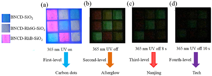
Thanks to the outstanding afterglow properties, these long-lived multicolor afterglow composites showed great potential for time-resolved and multiple-color advanced anticounterfeiting. Fig. 5 and Movies S1–S3 (Supporting information) show an encrypted QR code made with BNCD by screen printing on a blue fluorescent paper. The QR code is unrecognizable in daylight and 365 nm UV lamp because of the background interference. But when UV lamp was turned off, the green QR code appears because of the long-lifetime RTP properties of BNCD and the QR code can be recognized and displayed as "NJTECH". Given the time-dependent and multicolor afterglow, we further design the dynamic smart three-dimensional (3D) codes to anticounterfeiting. Based on time-resolved multicolor afterglow, we prepared a 3D code that carries different types of information for anticounterfeiting. In order to verify the application of 3D codes, a smart app was used to decode the time-resolved multicolor afterglow 3D codes. As shown in Fig. 6 and Movie S4 (Supporting information), under UV 365 nm, the 3D codes are decoded with the first-level information and presented as "Carbon dots". After turning off the UV lamp, the second-level information is reorganized as "Afterglow". When the UV lamp is turned off for 8 s, the afterglow of BNCD-RhB-SiO2 disappears and the third-level information is reorganized as "Nanjing". When the UV lamp is turned off for 10 s, the afterglow of BNCD-Rh6G-SiO2 disappears and the fourth level is displayed as "Tech".

In summary, we developed a simple strategy to prepare CD-based RTP materials by melting treatment of BA with various alkyl diamines. The introduction of boron and nitrogen is beneficial to increase the spin-orbit coupling and thus increases ISC to produce more triplet excitons. The cross-link of BA and alkyl diamines inhibited non-radiative transition. Hence, BNCD–BNCD-C5 all exhibited RTP properties. Furthermore, by studying the surface functional groups and interplanar spacing of BNCD–BNCD-C5, we found that the carbon-core state plays an important role in the RTP properties rather than the surface states. In particular, with the increase of alkyl, the interplanar spacing of the carbon core expands and CEE weakens, resulting in a decrease in phosphorescence intensity and lifetime. At the same time, due to the increasing of interplanar spacing, the electron cloud density of the carbon core decreases, which results in a blue shift of phosphorescent emission. Finally, based on TS-FRET, we employed intense and long-lived phosphorescent BNCD as the donor and short-lived fluorescent dyes (Rh6G and RhB) as acceptors to develop long-lived multicolor afterglow in silica. When the excitation light was turned off, BNCD, BNCD-SiO2, BNCD-Rh6G-SiO2 and BNCD-RhB-SiO2 all exhibited an afterglow that was visible to the naked eye for more than 10 s. The afterglow lifetimes are more than 0.9 s. Due to the outstanding afterglow properties, these materials were used for time-resolved and multiple-color advanced anticounterfeiting. We expect that this study may offer opportunities for designing advanced anticounterfeiting. The spatial effect and resonance energy transfer can promote the design of multicolor and long-lived afterglow materials and expand their applications.
The authors declare that they have no known competing financial interests or personal relationships that could have appeared to influence the work reported in this paper.
The authors greatly acknowledge the Natural Science Foundation of Jiangsu Province (No. BK20220351), Natural Science Foundation of the Jiangsu Higher Education Institutions of China (No. 22KJB150027) for financial support.
Supplementary material associated with this article can be found, in the online version, at doi:
H. Hu, Q. W. Chen, et al., J. Mater. Chem. 22 (2012) 11048–11053. doi: 10.1039/c2jm30169e
Y. Cui, R. S. Hegde, X. Ling, et al., Nanoscale 6 (2014) 282–288. doi: 10.1039/C3NR04375D
J. Andres, R. D. Hersch, J. E. Moser, A. S. Chauvin, Adv. Funct. Mater. 24 (2014) 5029–5036. doi: 10.1002/adfm.201400298
Z. An, C. Zheng, Y. Tao, et al., Nat. Mater. 14 (2015) 685–690. doi: 10.1038/nmat4259
X. Yang, D. Yan, Chem. Sci. 7 (2016) 4519–4526. doi: 10.1039/C6SC00563B
S. Cai, H. Shi, J. Li, et al., Adv. Mater. 29 (2017) 1701244. doi: 10.1002/adma.201701244
D. Li, F. Lu, J. Wang, et al., J. Am. Chem. Soc. 140 (2018) 1916–1923. doi: 10.1021/jacs.7b12800
B. Wang, S. Lu, Matter. 5 (2022) 110-149. doi: 10.1016/j.matt.2021.10.016
S. Lu, L. Sui, J. Liu, et al., Adv. Mater. 29 (2017) 1603443. doi: 10.1002/adma.201603443
X. Yang, L. Ai, J. Yu, et al., Sci. Bull. 67 (2022) 1450-1457. doi: 10.1016/j.scib.2022.06.013
B. Wang, Z. Wei, L. Sui, et al., Light Sci. Appl. 11 (2022) 172. doi: 10.1038/s41377-022-00865-x
X. Yang, X. Li, B. Wang, et al., Chin. Chem. Lett. 33 (2022) 613–625. doi: 10.1016/j.cclet.2021.08.077
Y. Sun, S. Liu, L. Sun, et al., Nat. Commun. 11 (2020) 5591. doi: 10.1038/s41467-020-19422-4
Q. Li, M. Zhou, Q. Yang, et al., Chem. Mater. 28 (2016) 8221-8227. doi: 10.1021/acs.chemmater.6b03049
P. Long, Y. Feng, C. Cao, et al., Adv. Funct. Mater. 28 (2018) 1800791. doi: 10.1002/adfm.201800791
W. Li, W. Zhou, Z. Zhou, et al., Angew. Chem. Int. Ed. 58 (2019) 7278-7283. doi: 10.1002/anie.201814629
S. Tao, S. Lu, Y. Geng, et al., Angew. Chem. Int. Ed. 57 (2018) 2393-2398. doi: 10.1002/anie.201712662
T. Takagahara, K. Takeda, Phys. Rev. B: Condens. Matter 46 (1992) 15578-15581. doi: 10.1103/PhysRevB.46.15578
H. Li, X. He, Z. Kang, et al., Angew. Chem. Int. Ed. 49 (2010) 4430-4434. doi: 10.1002/anie.200906154
Y. Liu, H. Huang, W. Cao, et al., Mater. Chem. Front. 4 (2020) 1586-1613. doi: 10.1039/d0qm00090f
S. Zhu, Y. Song, J. Wang, et al., Nano Today 13 (2017) 10-14. doi: 10.1016/j.nantod.2016.12.006
S. Tao, T. Feng, C. Zheng, S. Zhu, B. Yang, J. Phys. Chem. Lett. 10 (2019) 5182-5188. doi: 10.1021/acs.jpclett.9b01384
Y. Song, S. Zhu, S. Zhang, et al., J. Mater. Chem. C 3 (2015) 5976-5984. doi: 10.1039/C5TC00813A
Z. Yang, Z. Mao, Z. Xie, et al., Chem. Soc. Rev. 46 (2017) 915-1016. doi: 10.1039/C6CS00368K
A. Ajayaghosh, V.K. Praveen, C. Vijayakumar, Chem. Soc. Rev. 37 (2008) 109-122. doi: 10.1039/B704456A
W.R. Algar, N. Hildebrandt, S.S. Vogel, I.L. Medintz, Nat. Methods 16 (2019) 815-829. doi: 10.1038/s41592-019-0530-8
K.E. Sapsford, L. Berti, I.L. Medintz, Angew. Chem. Int. Ed. 45 (2006) 4562-4589. doi: 10.1002/anie.200503873
S. Kuila, S. J. George, Angew. Chem. Int. Ed. 59 (2020) 9393-9397. doi: 10.1002/anie.202002555
D. Chaudhuri, E. Sigmund, A. Meyer, et al., Angew. Chem. Int. Ed. 52 (2013) 13449-13452. doi: 10.1002/anie.201307601
R. Liang, L. Huo, A. Yu, et al., Chin. Chem. Lett. 33 (2022) 243-246. doi: 10.1016/j.cclet.2021.05.046
S. Cui, B. Wang, Y. Zan, et al., Chem. Eng. J. 431 (2022) 133373. doi: 10.1016/j.cej.2021.133373
Q. Li, S. Meng, Y. Li, et al., Carbon 195 (2022) 191-198. doi: 10.1016/j.carbon.2022.03.063
M. Zan, S. An, M. Jia, et al., Microchem. J. 172 (2022) 106878. doi: 10.1016/j.microc.2021.106878
Q. Feng, Z. Xie, M. Zheng, Chem. Eng. J. 420 (2021) 127647. doi: 10.1016/j.cej.2020.127647
C. Lin, Y. Zhuang, W. Li, et al., Nanoscale 11 (2019) 6584-6590. doi: 10.1039/c8nr09672d
J. Tan, R. Zou, J. Zhang, et al., Nanoscale 8 (2016) 4742-4747. doi: 10.1039/C5NR08516K
J. Liu, H. Zhang, N. Wang, et al., ACS Mater. Lett. 1 (2019) 58-63. doi: 10.1021/acsmaterialslett.9b00073
Y. Wu, X. Fang, J. Shi, W. Yao, W. Wu, Chin. Chem. Lett. 32 (2021) 3907-3910. doi: 10.1016/j.cclet.2021.04.040
Y. Zheng, Z. Wang, J. Liu, et al., ACS Appl. Mater. Interfaces 14 (2022) 15706-15715. doi: 10.1021/acsami.2c04141
L. Jiang, H. Ding, M. Xu, et al., Small 16 (2020) e2000680. doi: 10.1002/smll.202000680
Z. Zhou, Z. Song, J. Liu, et al., Adv. Optical Mater. 10 (2021) 2100704.
Z. Zhou, K. Jiang, N. Chen, et al., Mater. Lett. 276 (2020) 128226. doi: 10.1016/j.matlet.2020.128226
K.J. Mintz, M. Bartoli, M. Rovere, et al., Carbon 173 (2021) 433-447. doi: 10.1016/j.carbon.2020.11.017
S. Tao, C. Zhou, C. Kang, et al., Light. Sci. Appl. 11 (2022) 56. doi: 10.1038/s41377-022-00745-4
S. Zhu, Y. Song, J. Shao, X. Zhao, B. Yang, Angew. Chem. Int. Ed. 54 (2015) 14626-14637. doi: 10.1002/anie.201504951
S. Zhu, L. Wang, N. Zhou, et al., Chem. Commun. 50 (2014) 13845-13848. doi: 10.1039/C4CC05806B
S. Zhu, Y. Song, X. Zhao, et al., Nano Res. 8 (2015) 355–381. doi: 10.1007/s12274-014-0644-3
H. Liu, Y. Gu, Y. Dai, et al., J. Am. Chem. Soc. 142 (2020) 1153-1158. doi: 10.1021/jacs.9b11080
W. Ye, H. Ma, H. Shi, et al., Nat. Mater. 20 (2021) 1539-1544. doi: 10.1038/s41563-021-01073-5
Y. Chen, J.W.Y. Lam, R.T.K. Kwok, B. Liu, B.Z. Tang, Mater. Horiz. 6 (2019) 428-433. doi: 10.1039/C8MH01331D
Y.C. Liang, Q. Cao, K.K. Liu, et al., ACS Nano 15 (2021) 16242-16254. doi: 10.1021/acsnano.1c05234
S. Garain, B.C. Garain, M. Eswaramoorthy, S.K. Pati, S.J. George, Angew. Chem. Int. Ed. 60 (2021) 19720-19724. doi: 10.1002/anie.202107295
Q. Cao, K. Liu, Y. Liang, et al., Nano Lett. 22 (2022) 4097-4105. doi: 10.1021/acs.nanolett.2c00788
L. Zhang, M. Wu, Z. Wang, et al., ACS Sustain. Chem. Eng. 9 (2021) 16262-16269. doi: 10.1021/acssuschemeng.1c05525
M. Fu, Z. Feng, J. Wang, et al., Appl. Surf. Sci. 571 (2022) 151298. doi: 10.1016/j.apsusc.2021.151298
Y. Sun, X. Zhang, J. Zhuang, et al., Carbon 165 (2020) 306-316. doi: 10.1016/j.carbon.2020.04.030

Scheme 2 Schematic diagram of the preparation of long-lived multicolor afterglow based on TS-FRET.

Figure 1 (a) Phosphorescence spectra of BNCD, BNCD-C3, BNCD-C4 and BNCD-C5. (b) FTIR spectra of BNCD, BNCD-C3, BNCD-C4 and BNCD-C5. (c-f) XPS spectra of BNCD, BNCD-C3, BNCD-C4 and BNCD-C5.

Figure 2 (a-d) HR-TEM spectra of BNCD, BNCD-C3, BNCD-C4 and BNCD-C5. (e) PXRD spectra of BNCD, BNCD-C3, BNCD-C4 and BNCD-C5.

Figure 3 (a) UV-vis spectra of RhB and Rh6G, phosphorescence spectra of BNCD-SiO2. (b) Decay spectrum of BNCD-SiO2 with λex = 350 nm and λem = 512 nm. (c) Afterglow spectra of BNCD-SiO2, BNCD-Rh6G-SiO2 and BNCD-RhB-SiO2. (d) Decay spectrum of BNCD-Rh6G-SiO2 with λex = 360 nm and λem = 564 nm. (e) Decay spectrum of BNCD-RhB-SiO2 with λex = 360 nm and λem = 598 nm. (f) Proposed possible afterglow mechanism of BNCD-Rh6G-SiO2 and BNCD-RhB-SiO2 based on TS-FRET.

Figure 4 Afterglow images of (a) BNCD, (b) BNCD-SiO2, (c) BNCD-Rh6G-SiO2 and (d) BNCD-RhB-SiO2 under 365 nm light irradiation.

 扫一扫看文章

扫一扫关注我们
 DownLoad:

 下载:
下载:


 下载:
下载: