
Figure 1.
(a) Preparation scheme of FCP via oxygen activation. SEM and TEM images of (b, d) CP and (c, e) FCP. Elemental mapping of FCP (f) carbon and (g) oxygen.
Surface engineering towards high-energy carbon cathode for advanced aqueous zinc-ion hybrid capacitors
Xingyuan Gao , Huilin Deng , Yuanbin Fang , Yuyan Li , Xihong Lu

A variety of energy storage systems (ESS) have been developed for an efficient utilization of clean and renewable energy, such as lithium battery [1–3], aqueous battery [4–8], supercapacitor [9] and capacitor [10]. As an combination of capacitive carbon-based cathodes and battery-type Zn anode [11], zinc ion hybrid capacitors (ZIHCs) are featured with an impressive Zn anode specific capacity (~823 mAh/g), good stability in air and water, low oxidation-reduction potential (–0.76 V vs. SHE), environmentally friendliness and low cost, which exhibit a high potential for power storage and industrial production [12–18]. Relative to the Zn anode with an outstanding theoretical capacity, carbon-based cathode materials with a high chemical durability and superior conductivity still suffer from the unsatisfactory zinc ion storage capability, thus limiting the performance of ZIHCs [19].
To enhance the supercapacitive performance of ZIHCs, considerable efforts have been dedicated into the carbon cathode development so as to match the Zn anode. For example, a porous carbon that synthesized by carbonization of carbon/zeolite composite followed by acid etching delivered an admirable capacity of 0.081 mAh/cm2 [20]. Besides, the ZIHC based on carbon nanotube micro-cathode delivered a 29.6 µWh/cm2 energy density with 87.4% capacitance retention over 6000 cycles [21]. In another scenario, the ZIHC assembled with activated carbon presented a 115.4 µWh/cm2 energy density at 0.16 mW/cm2 [11]. Nevertheless, the specific surface area of carbonic cathode materials is still below expectation. Meanwhile, the inert carbon surface only allows physical Zn ion absorption in the Helmholtz layer, causing a poor intrinsic zinc ion storage capability. Thus, it is of great necessity to exploit a high-energy carbon-based cathode for ZIHCs [22].
Characterized with the admirable conductivity and cheap price, the commercial carbon paper (CP) derived from the reprocessing of carbon fiber is widely used as the support of electrode materials or current collectors. However, its application as an electrode material is rarely reported considering the low specific surface area and insufficient energy storage sites [23]. To address these issues, thermal treatment of oxygen-containing precursors [24] and acid etching [25] have been applied to increase the surface oxygen concentration as pseudocapacitive sites and surface area for electrolyte access, but their further applications are hindered by the uncontrollable oxidation degree, complex downstream treatment and waste stream. In the present study, a facile air activation approach is proposed for the one-step transformation of CP info a high-energy ZIHC cathode. The essential to enhance the energy storage capability of CP is to increase its accessible surface area and introduce oxygen functional groups for yielding pseudocapacitance simultaneously through air calcination treatment. The oxygen-groups functionalized carbon paper (FCP) with high capacity and good durability is easily realized by calcining CP at 500 ℃ in air for 4 h. Specifically, the as-fabricated ZIHC with FCP cathode delivered a significantly higher areal capacity (0.22 mAh/cm2), which outperforms the ZIHC with unmodified CP cathode by over 5000 times. Moreover, an excellent energy density and power density (130.8 µWh/cm2 and 7460.5 µW/cm2) are respectively approached at maximum with a 90% capacity retention after 10000 cycles, overmatching those recent reported ZIHCs.
Our approach to enhance the electrochemical properties of CP is to increase its surface oxygen-functional groups and surface area by thermally oxidizing FC in air (Fig. 1a). As observed from scanning electron microscopy (SEM) images of CP and FCP (Figs. 1b and c respectively), the surface of CP becomes rougher after oxidation, indicating a surface exfoliation and a possibly higher surface area. Transmission electron microscopy (TEM) was used for further characterizing the carbon surface morphology (Figs. 1d and e). Obviously, FCP presents a more irregular edge than CP. In particular, the FCP surface is exfoliated while CP exhibits regular flakes on the surface. Moreover, the regular lamellar lattice corresponding to the hexagonal graphite layer further confirms the fractured surface structure after oxidation activation. The resultant ultrathin graphene-liked edges are believed to offer active sites for zinc ion storage [26]. The elemental distribution was characterized by energy dispersive X-ray spectroscopy elemental mapping method. As visualized in Figs. 1f and g and Fig. S1 (Supporting information), a uniform dispersion of elemental carbon (red) and oxygen (green) was observed on the surface of FCP; in comparison, the pristine CP exhibited a much lower oxygen concentration (Fig. S2 in Supporting information).
X-ray photoelectron spectroscopy (XPS) was utilized to scrutinize the surface composition. No other signals are detected on the surface apart from C and O elements (Fig. 2a), suggesting the free of impurities. Fig. 2b presents the comparison of C 1s peaks between CP and FCP. Different from CP, four peaks can be deconvoluted in FCP spectrum, composing saturated C–C bond (284.9 eV), –C–OH (286.1 eV), > C=O (287.3 eV) and –COOH groups (288.7 eV) [27]. In addition to the more C–OH sites, the number of > C=O and –COOH were greatly increased for FCP, signifying a further oxidation of the surface carbon in the activation process (Fig. 2b). The evolution of oxygen species is also proven by the O 1s spectra (Fig. 2c). In particular, a much higher peak intensity was observed in FCP, indicating a significantly increased concentration of surface oxygen. Notably, different from the dominant existence of hydroxyl group for CP, considerably larger amounts of carbonyl and carboxyl groups were generated in FCP, in line with the results of C 1s spectra [20,28,29]. The higher concentration of surface oxygen might be responsible for a higher pseudocapacitance. In addition to the surface composition, XRD was applied to analyze the crystal structure (Fig. S3 in Supporting information). Clearly, the crystal forms of CP and FCP are highly consistent, suggesting the maintenance of hexagonal graphite crystalline during air oxidation (JCPDS No. 41-1487). Raman characterization was employed to investigate the carbon defects, where the defective and graphitic peaks were respectively located at 1350 and 1600 cm–1 in Fig. 2d [29]. After normalization, the ID/IG of CP and FCP is 0.838 and 0.926 respectively. The higher ID/IG of FCP is a result of the more edge/plane defects and surface oxygen functional groups generated by air oxidation [28].
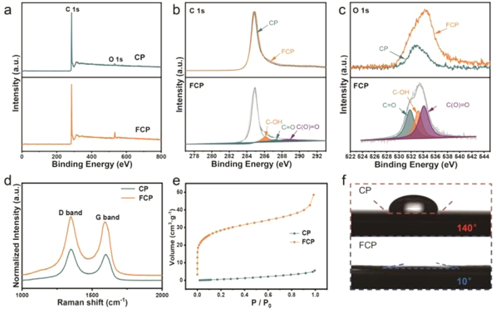
The effect of oxidation treatment on the surface area was investigated by nitrogen adsorption–desorption measurements. As seen from Fig. 2e, the adsorption curve of CP is of type III, while that of FCP is of type II, indicating the formation of more pores on the activated carbon surface. Moreover, the specific surface area increases tremendously after the treatment based on the volume of N2 adsorption. The specific surface area of FCP reaches 99.01 m2/g, 53 times higher than that of CP (1.85 m2/g). Besides, as shown in Fig. S4 (Supporting information), the kind of pores on the surface of both CP and FCP were mainly mesoporous. Notably, the percentage of small pores (< 2 nm) was much higher in FCP than CP. Moreover, the total number of pores for FCP was much higher, which indicated a larger pore volume as well. The above results symbolized an significantly improved surface accessible area for zinc ion diffusion and storage [20]. To characterize the hydrophilicity, the contact angle test was conducted in 1 mol/L ZnSO4 and the results are shown in Fig. 2f. The surface wettability is greatly improved after oxygen activation as reflected from the much smaller contact angle (10˚ vs. 140˚), which could be resulted from the abundant oxygen functional groups. The considerably improved surface wettability favors a low electrode–electrolyte interface resistance, facilitating the zinc ion transfer into the electrode surface [30].
In the electrochemical testing, commercial zinc sheet and 1 mol/L ZnSO4 were used as the anode and electrolyte; CP and FCP were adopted as the cathodes. Firstly, the electrochemical properties were measured by cyclic voltammetry (CV). According to Fig. S5a (Supporting information), FCP exhibits similar electrochemical behaviors during CV scans between 5 mV/s and 100 mV/s. It was noteworthy that no serious deformations were presented at high sweep rates, suggesting a rapid electrochemical reaction and good reversibility. Moreover, the slight redox peaks of FCP at 0.8 and 1.2 V indicate the existence of pseudocapacitive behavior [21]. The better zinc ion storage capability of FCP is further proven by the much larger enclosed area of CV curve in Fig. 3a. In addition to CV, galvanostatic charge discharge (GCD) test was conducted to study the electrochemical activities. The areal specific capacity of FCP-based ZIHC approaches to 0.22 mAh/cm2 at 1 mA/cm2, outperforming the CP-based counterpart by 5281 times (Fig. 3b). The ZIHC with FCP also outperforms the reported capacity performances in literatures (Fig. 3c), such as oxidized carbon nanotubes (O-CNT) [31], hollow carbon sphere (HCS) [32], porous carbon (PC) [20] and activated carbon (AC) [13]. Moreover, after a 30-time increase of current density, the capacity of FCP still maintains about 32.0% of the initial value, suggesting a good rate performance in consonance with the CV results (Fig. 3d and Fig. S5b in Supporting information). The cycling stability was tested under the current of 12 mA/cm2. Based on the GCD curves of CP and FCP (Fig. 3e), the capacity of CP almost decays to 0 after less than 6000 cycles due to the limited surface area and pseudocapacitive sites for zinc ion storage and conversion, while that of FCP still realizes a more than 90% capacity retention over 10000 cycles. As shown in the SEM image of FCP after 10000 cycles (Fig. S6 in Supporting information), no obvious damage is observed on the surface, which is a proof of the excellent structural stability.

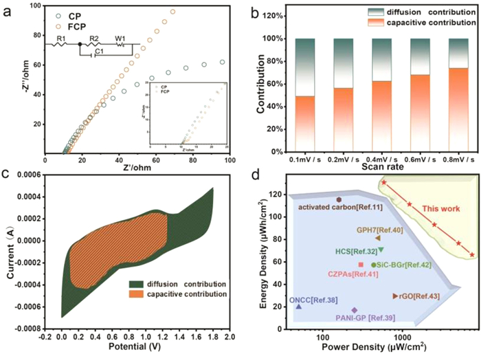
To gain insight into the enhanced capacitive performances of FCP, the resistance of FCP and CP cathodes was evaluated by electrochemical impedance spectroscopy (EIS) analysis. As shown in Fig. 4a, a slightly larger semicircle diameter located at the high-frequency domain of Nyquist plots refers to a bit higher charge transfer resistance of FCP (1.4 Ω vs. 0.6 Ω), as a proof of the introduction of oxygen functional groups as pseudocapacitive sites via air activation. Meanwhile, the larger slope for FCP at the low-frequency region suggested a smaller Warburg impedance and thus a faster zinc ion diffusion (39.0 Ω vs. 74.6 Ω) [33].
To explore the kinetics evolution of FCP in the electrochemical process, the following method was applied based on the CV curves under different sweep rates [34,35]. The current expression is shown as follow:
|
|
(1) |
where i refers to the current at the corresponding sweep rate, . ν represents the scan rate, k1ν stands for the capacitive-controlled current; k2ν1/2. is the diffusion-controlled current [33]. Contribution ratios at different scanning rates (Fig. 4b) were collected based on Eq. 1 and CV curves of FCP in Fig. S7 (Supporting information). Since the diffusion process is relatively slow, the proportion of capacitive capacity increases with the scanning rate. Moreover, the capacitive contribution is higher than that of the diffusion at most of the scan rates (except for the equal contribution at 0.1 mV/s) [36]. In particular, the fast kinetics capacitive effect dominates the capacity at 0.8 mV/s (74.0% vs. 26.0%), suggesting the introduction of much more pseudocapacitive active sites by air activation (Fig. 4c). Based on the experimental results, the outstanding capacitive performances of FCP are a result of enlarged surface area and increased surface oxygen groups, which result in more pseudocapacitive active sites, a larger electrochemical reaction area, and enhanced surface wettability [29,37].
To highlight the outstanding merits of FCP, the as-fabricated ZIHC are compared with reported devices regarding the energy and power density (Fig. 4d). In particular, the Zn//FCP ZIHC in this work exhibits a superb energy and power density of 130.8 µWh/cm2 and 7460.5 µW/cm2 at maximum respectively, overmatching the majority of reported capacitors at similar current densities, such as N-doped carbon fiber cloth with oxygeneous groups (ONCC) (19.8 µWh/cm2 and 50.1 µW/cm2) [38], hollow carbon spheres (HCS) (71.4 µWh/cm2 and 537.4 µW/cm2) [32], polyaniline coated graphene paper (PANi-GP) (17 µWh/cm2 and 250 µW/cm2) [39], activated carbon (AC) (115.4 µWh/cm2 and 160 µW/cm2) [11], graphene/polyaniline hydrogel (GPH7) (81.3 µWh/cm2 and 500 µW/cm2) [40], carbon cloth/ZIF-67/polypyrrole composites (CZPAs) (57.6 µWh/cm2 and 301.0 µW/cm2) [41], boron-doped graphene with silicon carbide (SiC-BGr) (57.3 µWh/cm2 and 437.1 µW/cm2) [42] and reduced graphene oxide (rGO) (29.6 µWh/cm2 and 800 µW/cm2) [43].
To conclude, a simple surface engineering approach is reported for converting the commercial carbon paper (CP) into a highly active FCP cathode for ZIHC. The capacitive properties of FCP are considerably boosted owing to the much larger specific surface area and increased amounts of oxygen functional groups after air activation. Owing to the larger electrochemical reaction area, more pseudocapacitive active sites and improved surface hydrophilicity, the specific areal capacity of as-fabricated ZIHC based on FCP cathode approaches to 0.22 mAh/cm2, outperforming the ZIHC with blank CP by 5281 times. Moreover, a superb energy and power density of 130.8 µWh/cm2 and 7460.5 µW/cm2 at maximum are respectively delivered with over 90% capacity retention over 10,000 cycles. The present study sheds light on exploiting a wide range of high-energy carbon-based electrodes via a simple surface engineering strategy.
The authors declare that they have no known competing financial interests or personal relationships that could have appeared to influence the work reported in this paper.
This research was funded by Key Scientific Research Projects of General Universities in Guangdong Province, China (No. 2021KCXTD086), Guangzhou Basic and Applied Basic Research Project in China (No. 202102020134) and Youth Innovation Talents Project of Guangdong Universities (natural science) in China (No. 2019KQNCX098).
Supplementary material associated with this article can be found, in the online version, at doi:
P. Simon, Y. Gogotsi, B. Dunn, Science 343 (2014) 1210. doi: 10.1126/science.1249625
C. Yang, J. Chen, X. Ji, et al., Nature 569 (2019) 245–250. doi: 10.1038/s41586-019-1175-6
N.S. Choi, Z. Chen, S.A. Freunberger, et al., Angew. Chem. Int. Ed. 51 (2012) 9994–10024. doi: 10.1002/anie.201201429
X. He, H. Zhang, X. Zhao, et al., Adv. Sci. 6 (2019) 1900151. doi: 10.1002/advs.201900151
M. Song, H. Tan, D. Chao, H.J. Fan, Adv. Funct. Mater. 28 (2018) 1802564. doi: 10.1002/adfm.201802564
Y. Geng, L. Pan, Z. Peng, et al., Energy Storage Mater. 51 (2022) 733–755. doi: 10.1016/j.ensm.2022.07.017
Q. Li, L. Han, Q. Luo, X. Liu, J. Yi, Batter. Supercaps 5 (2022) e202100417. doi: 10.1002/batt.202100417
K. Wu, J. Cui, J. Yi, et al., ACS Appl. Mater. Inter. 14 (2022) 34612–34619. doi: 10.1021/acsami.2c05887
N. Jabeen, A. Hussain, Q. Xia, et al., Adv. Mater. 29 (2017) 1700804. doi: 10.1002/adma.201700804
H. Xu, Y. Wang, X. Liao, B. Shi, J. Energy Chem. 47 (2020) 324–332. doi: 10.1016/j.jechem.2020.02.001
P. Zhang, Y. Li, G. Wang, et al., Adv. Mater. 31 (2019) 1806005. doi: 10.1002/adma.201806005
G.A. Snook, P. Kao, A.S. Best, J. Power Sources 196 (2011) 1–12. doi: 10.1016/j.jpowsour.2010.06.084
L. Dong, X. Ma, Y. Li, et al., Energy Storage Mater. 13 (2018) 96–102. doi: 10.1016/j.ensm.2018.01.003
N. Guo, W. Huo, X. Dong, et al., Small Methods 6 (2022) 2200597. doi: 10.1002/smtd.202200597
K. Wu, F. Ning, J. Yi, et al., J. Energy Chem. 69 (2022) 237–243. doi: 10.1016/j.jechem.2022.01.037
L. Zhang, L. Miao, W. Xin, et al., Energy Storage Mater. 44 (2022) 408–415. doi: 10.1016/j.ensm.2021.10.033
M. Yang, Z. Yan, J. Xiao, et al., Angew. Chem. Int. Ed. 61 (2022) e202212666. doi: 10.1002/anie.202212666
M. Wang, Y. Meng, K. Li, et al., eScience 2 (2022) 509–517. doi: 10.1016/j.esci.2022.04.003
Q. Liu, H. Zhang, J. Xie, X. Liu, X. Lu, Carbon Energy 2 (2020) 521–539. doi: 10.1002/cey2.69
H.Z. Zhang, Q.Y. Liu, Y.B. Fang, et al., Adv. Mater. 31 (2019) 1904948. doi: 10.1002/adma.201904948
G. Sun, H. Yang, G. Zhang, et al., Energy Environ. Sci. 11 (2018) 3367–3374. doi: 10.1039/C8EE02567C
L. Dong, W. Yang, W. Yang, et al., J. Mater. Chem. A 7 (2019) 13810–13832. doi: 10.1039/C9TA02678A
G. Wang, H. Wang, X. Lu, et al., Adv. Mater. 26 (2014) 2676–2682. doi: 10.1002/adma.201304756
B. Liu, Y.J. Liu, H.B. Chen, M. Yang, H.M. Li, J. Power Sources 341 (2017) 309–317. doi: 10.1016/j.jpowsour.2016.12.022
J.H. Park, H.J. Lee, J.Y. Cho, et al., ACS Appl. Mater. Interfaces 12 (2020) 1322–1329. doi: 10.1021/acsami.9b17311
M. Yu, Y. Huang, C. Li, et al., Adv. Funct. Mater. 25 (2015) 324–330. doi: 10.1002/adfm.201402964
Y. Lu, Z. Li, Z. Bai, et al., Nano Energy 66 (2019) 104132. doi: 10.1016/j.nanoen.2019.104132
W. Wang, W. Liu, Y. Zeng, et al., Adv. Mater. 27 (2015) 3572–3578. doi: 10.1002/adma.201500707
H. Zhang, W. Qiu, Y. Zhang, et al., J. Mater. Chem. A 4 (2016) 18639–18645. doi: 10.1039/C6TA08138J
M. Yu, X. Chen, Y. Zeng, et al., Angew. Chem. Int. Ed. 55 (2016) 6762–6766. doi: 10.1002/anie.201602631
Y. Tian, R. Amal, D.W. Wang, Front. Energy Res. 4 (2016) 34.
S. Chen, L. Ma, K. Zhang, et al., J. Mater. Chem. A 7 (2019) 7784–7790. doi: 10.1039/C9TA00733D
Y. Han, Y. Lu, S. Shen, et al., Adv. Funct. Mater. 29 (2019) 1806329. doi: 10.1002/adfm.201806329
H. Li, Q. Yang, F. Mo, et al., Energy Storage Mater. 19 (2019) 94–101. doi: 10.1016/j.ensm.2018.10.005
J. Wang, J. Polleux, J. Lim, B. Dunn, J. Phys. Chem. C 111 (2007) 14925–14931. doi: 10.1021/jp074464w
T. Brezesinski, J. Wang, S.H. Tolbert, B. Dunn, Nat. Mater. 9 (2010) 146–151. doi: 10.1038/nmat2612
P. Liu, W. Liu, Y. Huang, et al., Energy Storage Mater. 25 (2020) 858–865. doi: 10.1016/j.ensm.2019.09.004
Y. Zheng, W. Zhao, D. Jia, L. Cui, J. Liu, Chem. Eng. J. 364 (2019) 70–78. doi: 10.1016/j.cej.2019.01.076
K. Li, X. Liu, S. Chen, W. Pan, J. Zhang, J. Energy Chem. 32 (2019) 166–173. doi: 10.1016/j.jechem.2018.07.014
Y. Zou, Z. Zhang, W. Zhong, W. Yang, J. Mater. Chem. A 6 (2018) 9245–9256. doi: 10.1039/C8TA01366G
Q. Wang, Y. Wang, T. Zhang, et al., Electrochim. Acta 407 (2022) 139869. doi: 10.1016/j.electacta.2022.139869
K. Zhu, M. Li, C. Li, X. Xuan, H. Li, Chem. Eng. J. 433 (2022) 133576. doi: 10.1016/j.cej.2021.133576
G. Sun, Y. Xiao, B. Lu, et al., ACS Appl. Mater. Inter. 12 (2020) 7239–7248. doi: 10.1021/acsami.9b20629

Figure 1 (a) Preparation scheme of FCP via oxygen activation. SEM and TEM images of (b, d) CP and (c, e) FCP. Elemental mapping of FCP (f) carbon and (g) oxygen.

Figure 2 XPS spectra of FCP and CP. (a) Survey, (b) C 1s, (c) O 1s. (d) Raman spectra of FCP and CP. (e) N2 physisorption isotherms of FCP and CP. (f) Contact angle measurements on FCP and CP.


Figure 4 (a) Nyquist plots of CP and FCP electrodes. (b) Ratios of capacitive and diffusion contributions at various sweep rates. (c) Capacitive and diffusion contributions to charge storage controlled by at 0.8 mV/s. (d) Ragone plots of the FCP-based ZIHC. Other reported capacitors are added for comparison [11,32,38–43].

 扫一扫看文章

扫一扫关注我们
 DownLoad:
 下载:
下载:
 下载:
下载: