Citation:
Ang Li, Mengke Huang, Die Hu, Zhaodi Tang, Jianhang Xu, Yang Li, Xiaowei Zhang, Xiao Chen, Ge Wang. Polydopamine-coated metal-organic framework-based composite phase change materials for photothermal conversion and storage[J]. Chinese Chemical Letters,
2023, 34(8): 107916.
doi:
10.1016/j.cclet.2022.107916
Polydopamine-coated metal-organic framework-based composite phase change materials for photothermal conversion and storage
English
Polydopamine-coated metal-organic framework-based composite phase change materials for photothermal conversion and storage
School of Materials Science and Engineering, Suzhou University of Science and Technology, Suzhou 215009, China
b.
Beijing Advanced Innovation Center for Materials Genome Engineering, Beijing Key Laboratory of Function Materials for Molecule & Structure Construction, School of Materials Science and Engineering, University of Science and Technology Beijing, Beijing 100083, China
c.
Institute of Advanced Materials, Beijing Normal University, Beijing 100875, China
d.
Key Laboratory of Low-grade Energy Utilization Technologies and Systems (Chongqing University), Ministry of Education of China, Chongqing University, Chongqing 400044, China
e.
Shunde Graduate School, University of Science and Technology Beijing, Shunde 528399, China
gewang@ustb.edu.cn (G. Wang). 1 These authors contributed equally to this work.
Received Date:
29 August 2022 Accepted Date:
17 October 2022 Revised Date:
08 October 2022 Available Online:
15 August 2023
Abstract:
The liquid leakage and weak solar absorption capacity of organic phase change materials (PCMs) seriously hinder the efficient utilization of solar energy and thermal energy storage. To address these issues, we prepared nanoporous metal organic framework (Ni-MOF) for the vacuum infiltration of paraffin wax (PW), followed by the coating of solar-absorbing functional polydopamine (PDA) on the surface of PW@MOF for photothermal conversion and storage. As an efficient photon harvester, PDA coating endows PW@MOF/PDA composite PCMs with excellent photothermal conversion and storage properties due to the robust broadband solar absorption capability in the UV–vis region. Resultantly, our prepared PW@MOF/PDA composite PCMs exhibit a high photothermal conversion and storage efficiency of 91.2%, while that of PW@MOF composite PCMs is only zero. In addition, PW@MOF/PDA composite PCMs also exhibit excellent thermal stability, shape stability, energy storage stability, and photothermal conversion stability. More importantly, this coating strategy is universal by integrating different MOFs and solar absorbers, showing the potential to accelerate the major breakthroughs of high-efficiency MOF-based photothermal composite PCMs in solar energy utilization.
Solar energy is the radiant energy released by high-temperature nuclear fusion reactions inside the sun. Solar energy may be the best choice for the future world due to the following reasons. As the most abundant renewable energy, the solar energy reaching the earth's surface every year is about 130 trillion tons of standard coal, which is equivalent to 10,000 times the sum of all kinds of energy currently consumed by the world every year. The inexhaustible solar energy provides stable and increasing output efficiency compared to other energy sources. However, solar energy is weather- and geographic-dependent, and its intermittency results in a discrepancy between energy supply and demand. Emerging thermal energy storage technologies can effectively address the fluctuation and intermittence of solar energy. Compared with thermochemical heat storage and sensible heat storage, latent heat storage using phase change materials (PCMs) has received extensive attention due to large thermal energy storage density, small volume evolution and constant operation temperature [1]. However, pristine organic PCMs usually suffer from liquid leakage and weak solar absorption in solar energy utilization, which seriously hinder the efficient utilization of solar energy and thermal energy storage [2]. To address the liquid leakage issue, diversified nanoporous supporting materials have been developed to encapsulate PCMs to prepare shape-stabilized composite PCMs, especially graphene, graphene derivatives and carbon nanotubes [3–6]. To boost the solar absorption capability, two strategies are usually adopted. One strategy is to encapsulate PCMs using strong solar-absorbing porous supporting materials. Another strategy is to introduce strong solar-absorbing agents into PCMs, such as organic dyes (indocyanine green, blue anthraquinone) [7–9] and organic polymers (polypyrrole, polyaniline, polydopamine) [10–12].
Recently, solar-absorbing agent-assisted photothermal composite PCMs have taken a big step forward. For instance, Wang et al. [9] grafted blue anthraquinone dye on graphene oxide (GO), and the obtained GO-based composite PCMs exhibited a photothermal conversion and storage efficiency of 86.6%. Yan et al. [8] prepared a reactive black 5 (RB5) dye-grafted SiO2 to encapsulate polyethylene glycol (PEG), and the obtained PEG/SiO2-dye composite PCMs exhibited a photothermal conversion and storage efficiency of 88%. Cao et al. [13] incorporated polypyrrole (PPy) into the phase change polymers composed of poly(4-vinylpyridine) and stearic acid. The prepared composite PCMs exhibited a photothermal conversion and storage efficiency of 87.8%. Wu et al. [14] prepared PDA-coated melamine foam for the encapsulation of PW, with a photothermal conversion and storage efficiency of 80.8%. Du et al. [15] introduced PDA-decorated MXene into PEG-based polyurethane PCMs, with a photothermal conversion and storage efficiency of up to 90.1% due to the synergistic reinforcement of MXene and PDA. Although the photothermal conversion and storage efficiency of composite PCMs has been greatly optimized, there is still room for further improvement. Therefore, how to obtain higher photothermal conversion and storage efficiency while ensuring good shape stability, energy storage stability, and photothermal conversion stability still needs to be explored.
Emerging metal-organic frameworks (MOFs) are organic-inorganic hybrid nanoporous materials that are self-assembled through the coordination of organic linkers and metal-containing nodes, which can be rationally designed by screening the appropriate organic linkers and metal centers [16–19]. Benefiting from ultrahigh surface area, adjustable pore size, and large pore volume, MOFs are being gradually applied in the field of phase change thermal energy storage recently [20]. However, the integration of pristine MOFs and PCMs is difficult to trigger the photothermal conversion and storage due to the weak photon capture ability of pristine MOFs and PCMs. Herein, we developed advanced pristine MOF-based photothermal composite PCMs by coating photon absorber PDA on the surface of PW@MOF, which can also function as a phonon enhancer. Resultantly, PW@MOF/PDA composite PCMs exhibit robust broadband solar absorption capability in the UV–vis region, and higher heat transfer ability than PW@MOF. More importantly, PW@MOF/PDA composite PCMs exhibit a high photothermal conversion and storage efficiency of 91.2%. In addition, PW@MOF/PDA composite PCMs also exhibit excellent thermal stability, shape stability, energy storage stability, and photothermal conversion stability. We hope this universal coating strategy can accelerate the major breakthroughs of photothermal composite PCMs in solar energy utilization.
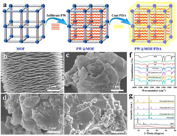
Pristine MOF-based photothermal composite PCMs were prepared by coating solar absorber PDA on the surface of PW@MOF through hydrothermal reaction, vacuum infiltration and chemical polymerization methods. The preparation of PW@MOF/PDA composite PCMs is schematically shown in Fig. 1a. As seen from the SEM images (Figs. 1b-e), the prepared Ni-MOF exhibits a regular accordion-like shape. After dopamine hydrochloride is chemically polymerized on the surface of PW@MOF, the microscopic morphologies of PW@MOF/PDA composite PCMs have undergone significant evolution from accordion-like shape to irregular shape. With the increase of PDA content, spherical particles begin to appear on the surface of PW@MOF/PDA composite PCMs. FTIR was conducted to detect the surface chemical status of the samples. As shown in Fig. 1f, the peaks located at 3412 cm−1 and 3000 cm−1 of PW are attributed to C—H stretching vibration. The peaks located at 3605 cm−1, 1578 cm−1 and 1372 cm−1 of Ni-MOF are attributed to -OH stretching vibration, C—N stretching vibration and C—H bending vibration, respectively. The peak at 3385 cm−1 of PDA is attributed to N—H stretching vibration, and the peak at 1590 cm−1 is attributed to the stretching vibration of benzene ring. The most functional groups of Ni-MOF are maintained after infiltrating PW and coating PDA, indicating high structural stability of Ni-MOF framework. Comparing the FTIR spectra of MOF, PDA, PW and PW@MOF/PDA composite PCMs, the main characteristic peaks of MOF, PDA, and PW can all be observed in PW@MOF/PDA composite PCMs without emerging new peaks, indicating that the interaction between PW molecules and MOF/PDA is just simple physical combination without chemical interaction.
Figure 1
Figure 1.
(a) Preparation schematic of PW@MOF/PDA composite PCMs for photothermal conversion and storage. (b-e) SEM images of Ni-MOF, PW@MOF/PDA-10%, PW@MOF/PDA-20% and PW@MOF/PDA-30%. (f) FTIR spectra of MOF, PDA, PW, PW@MOF, PW@MOF/PDA. (g) XRD patterns of MOF, PDA, PW@MOF, PW@MOF/PDA.
To explore the influence of MOF/PDA on the phase transition behaviors of PW molecules, XRD measurement was performed. As shown in Fig. 1g, Figs. S1 and S2 (Supporting information), the crystal characteristic peaks of PW are located at 21.5° and 23.9°, and the characteristic peak of PDA is around 21° After infiltrating PW and coating PDA, Ni-MOF still has only two main diffraction peaks at 9° and 16°, indicating the excellent structural stability of Ni-MOF framework. Since the characteristic peak intensity of PW is much larger than that of PDA, the characteristic peak of PDA is covered by the characteristic peak of PW. Therefore, the XRD pattern of PW is plotted separately (Fig. S1). Comparing the XRD patterns of PW and PW@MOF/PDA composite PCMs, the main characteristic peaks of PW can be observed in PW@MOF/PDA composite PCMs without emerging new crystal planes, indicating that the introduction of MOF/PDA does not interfere with the crystal structure of PW molecules. It can be concluded that PW molecules are capable of free phase transition within the nanopores of Ni-MOF. The strong physical interaction between PW and MOF/PDA can effectively prevent the liquid leakage of PW during the phase transition process.
PW is a typical solid-liquid PCM, which is prone to liquid leakage during the phase change process. The strong capillary force excited by the pores of Ni-MOF can effectively adsorb and stabilize PW molecules. Therefore, porous Ni-MOF with good encapsulation ability to stabilize PW is helpful for its practical application. To visually demonstrate the shape stability of PW@MOF/PDA composite PCMs, the cylindrical samples (PW and PW@MOF/PDA) with the same diameter (12.7 mm) and thickness (2.0 mm) were simultaneously placed in an oven at 80 ℃, and a digital camera was used to record the shape evolution during the heating process. The evaluation results of shape stability are shown in Fig. S2. At 25 ℃, PW is a white solid, while PW@MOF/PDA-20% is a black solid due to the introduction of PDA. After heating for 5 min, PW begins to melt and leak, while PW@MOF/PDA-20% remains solid without any leakage. After heating for 15 min, PW melts sharply with poor shape stability, while PW@MOF/PDA-20% still retains the initial cylindrical shape with good shape stability. These phenomena indicate that when the ambient temperature is higher than the melting point of PW, MOF/PDA can effectively prevent PW leakage and PW@MOF/PDA-20% exhibits excellent shape stability.
Phase change enthalpy is the most reliable indicator for evaluating the thermal properties of composite PCMs. The thermal properties of PW@MOF/PDA composite PCMs with different PDA contents were characterized by DSC (Fig. 2). Detailed thermal performance data is summarized in Table S1 (Supporting information). The melting enthalpy and solidification enthalpy of pristine PW are 200.01 J/g and 192.88 J/g, respectively. The melting enthalpy and solidification enthalpy of PW@MOF composite PCMs are 118.39 J/g and 119.03 J/g, respectively. In contrast, the phase change enthalpies of PW@MOF/PDA composite PCMs exhibit a decreasing trend with the increase of the surface coating ratio of PDA due to the inactive heat storage feature of PDA. In detail, the melting enthalpy and solidification enthalpy of PW@MOF/PDA composite PCMs gradually degrade from 109.71 J/g (PW@MOF/PDA-10%) to 75.15 J/g (PW@MOF/PDA-30%), from 109.67 J/g (PW@MOF/PDA-10%) to 74.88 J/g (PW@MOF/PDA-30%), respectively.
Figure 2
Figure 2.
(a, b) DSC curves of PW, PW@MOF, PW@MOF/PDA. (c, d) Phase change enthalpies and phase change temperatures of PW, PW@MOF, PW@MOF/PDA.
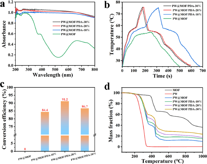
Nowadays, the utilization of sustainable energy has become increasingly important. Collecting and storing solar energy through PCMs is both environmentally friendly and economically feasible, however, pristine PCMs are poor solar absorbers. Herein, we coated PDA as solar absorber on the surface of PW@MOF composite PCMs for photothermal conversion and storage. The optical properties of the samples were characterized by UV–vis spectrophotometer. As shown in Fig. 3a, PW@MOF composite PCMs exhibit very poor solar absorption capacity due to the low solar capture capabilities of both PW and Ni-MOF. Compared with PW@MOF, PW@MOF/PDA has significantly improved absorption in both UV and visible light bands. Meanwhile, the solar absorption intensity of PW@MOF/PDA increases with the increase of surface-coated PDA content, enabling faster photothermal conversion rate. This phenomenon suggests that PDA is an efficient solar absorber, which can efficiently absorb solar energy and convert it into heat energy.
Figure 3
Figure 3.
(a) UV–vis absorption spectra of PW@MOF and PW@MOF/PDA. (b) Photothermal conversion and storage curves of PW@MOF and PW@MOF/PDA under a light irradiation of 150 mW/cm2. (c) Photothermal conversion and storage efficiencies of PW@MOF and PW@MOF/PDA. (d) TGA curves of MOF, PW, PW@MOF and PW@MOF/PDA.
To evaluate the photothermal conversion and thermal energy storage capabilities of composite PCMs, PW@MOF/PDA composite PCMs with different contents of PDA were tested under the simulated sunlight of 150 mW/cm2. A temperature sensor was used to record the temperature evolution over time of the samples exposed to solar radiation (Fig. 3b). Compared with PW@MOF, the temperature rise of PW@MOF/PDA is faster, indicating that the coated PDA can effectively enhance the thermal conductivity of PW@MOF. Because PDA can form hydrogen bonds with PW@MOF due to the existence of a large number of amino groups and hydroxyl groups, which can improve the interface compatibility and reduce the interface thermal resistance. It is worth noting that PW@MOF composite PCMs cannot be triggered to achieve photothermal conversion and storage even for long enough solar radiation. Because PW@MOF composite PCMs are unable to raise the temperature above the phase change temperature of PW under solar irradiation due to their poor solar absorption capacity. While the temperature of PW@MOF/PDA composite PCMs rises above the phase change temperature of PW after being irradiated for a certain period of time, and start to convert the captured solar energy into thermal energy which is stored in PW in the form of latent heat due to the excellent photothermal effect of PDA. During the photothermal conversion and storage process, a temperature plateau appearing on the curves of PW@MOF/PDA composite PCMs corresponds to the melting endothermic process of PW, accompanied by a large amount of thermal effects. After removing the simulated sunlight, a temperature plateau emerges again during the cooling process of PW@MOF/PDA composite PCMs, corresponding to the crystallization exothermic process of PW. After calculation, the average photothermal conversion rates of PW@MOF, PW@MOF/PDA-10%, PW@MOF/PDA-20%, PW@MOF/PDA-30% are 0.12, 0.16, 0.27, 0.29 ℃/s, respectively (Fig. S4 in Supporting information). It is worth noting that the average photothermal conversion rate of PW@MOF/PDA composite PCMs is gradually enhanced with the increase of PDA due to the excellent light capture capability of PDA. In particular, the average photothermal conversion rate of PW@MOF/PDA-30% is significantly enhanced compared with PW@MOF. It can be concluded that high fraction of PDA enables more efficient photothermal conversion rate.
To further quantify the photothermal conversion and storage capability of composite PCMs, we calculated the photothermal conversion and storage efficiency (η) by the following equation:
(1)
where M is the mass of the samples, ΔH is the latent heat, P is the radiation intensity of the simulated sunlight, S is the surface area of the samples, Tt and Tf are the starting and ending time of phase change process [21]. After calculation, the photothermal conversion and storage efficiencies of PW@MOF/PDA-10%, PW@MOF/PDA-20% and PW@MOF/PDA-30% are 84.4%, 91.2% and 86.7%, respectively (Fig. 3c). While the photothermal conversion and storage efficiency of PW@MOF is zero because solar irradiation cannot trigger its photothermal conversion and storage. PW@MOF/PDA-20% composite PCMs obtain the highest photothermal conversion and storage efficiency explained as follows. PW@MOF/PDA-20% and PW@MOF/PDA-30% exhibit the similar photothermal conversion and storage curves. However, the latent heat of PW@MOF/PDA-30% is significantly lower than that of PW@MOF/PDA-20%. Therefore, according to the calculation formula, it can be concluded that PW@MOF/PDA-20% composite PCMs have the highest photothermal conversion and storage efficiency. These results indicate that the moderate introduction of PDA with high photothermal effect enhances the photothermal conversion and storage efficiency of PW@MOF/PDA composite PCMs.
Thermal stability is an important evaluation index for the development and application of composite PCMs. The thermal stability of the samples was characterized by TGA, as shown in Fig. 3d. Ni-MOF begins to undergo pyrolysis at 100 ℃ due to the evaporation of adsorbed water molecules. When the temperature is increased to 375 ℃, a significant mass drop emerges, which is attributed to the pyrolysis of Ni-MOF framework. The mass loss between 100 ℃ and 375 ℃ is attributed to the pyrolysis of residual organic solvents inside the channels of Ni-MOF. When the temperature is gradually increased to 1000 ℃, the final residue of Ni-MOF is mainly composed of carbon and metallic nickel, with a mass fraction of about 40 wt%. The starting and finishing pyrolysis temperatures of PW are about 200 ℃ and 350 ℃, respectively. It is worth noting that the termination pyrolysis temperatures of PW@MOF/PDA composite PCMs with different mass fractions of PDA are all about 600 ℃. Furthermore, the introduction of Ni-MOF can enhance the thermal stability of PW compared with PW, due to the higher thermal stability of Ni-MOF. Thermal stability analysis indicates that PW@MOF/PDA composite PCMs exhibit excellent thermal stability in the application scenarios of low and medium temperature thermal energy storage.
Cyclic stability is very important for composite PCMs in practical applications. In this study, we choose PW/MOF/PDA-20% as the optimized sample by comprehensively considering the endothermic, exothermal, light absorption and photothermal conversion properties of PW/MOF/PDA composite PCMs with different mass fractions of PDA. Firstly, the optimal PW@MOF/PDA-20% composite PCMs are subjected to 50 melting-freezing cycles. Then, we analyzed FTIR, XRD and DSC results of PW@MOF/PDA-20% composite PCMs after undergoing 50 melting-freezing cycles (Figs. 4a-c). Resultantly, the phase compositions and functional groups of PW@MOF/PDA-20% composite PCMs are almost unchanged before and after 50 melting-freezing cycles. More importantly, the phase change temperature (65.52 and 52.90 ℃) and latent heat (98.89 and 102.57 J/g) of PW@MOF/PDA-20% composite PCMs after 50 melting-freezing cycles are almost similar to that before 50 melting-freezing cycles, indicating ultrahigh latent heat retention. The FTIR, XRD and DSC results indicate that PW@MOF/PDA-20% composite PCMs exhibit excellent thermal cycle stability. Additionally, the photothermal conversion and storage cyclic stability is also very important for composite PCMs. As shown in Fig. 4d, the photothermal conversion and storage curves after undergoing 50 cycles are almost consistent with the original curves, indicating excellent cyclic stability of photothermal conversion and storage with a high efficiency. The structural evolution of PW@MOF/PDA-20% from crystalline state to amorphous state during melting and freezing cycles is schematically shown in Fig. 4e.
Figure 4
Figure 4.
(a) FTIR spectra of PW@MOF/PDA-20% after 50 melting-freezing cycles. (b) XRD patterns of PW@MOF/PDA-20% after 50 melting-freezing cycles. (c) DSC curves of PW@MOF/PDA-20% after 50 melting-freezing cycles. (d) Photothermal conversion and storage curves after 50 cycles. (e) Schematic of the structural evolution of PW@MOF/PDA-20% during melting and freezing cycles.
In conclusion, we designed PW@MOF/PDA composite PCMs for photothermal conversion and storage by coating solar absorber PDA on the surface of PW@MOF through hydrothermal reaction, vacuum infiltration and chemical polymerization methods. Compared with PW@MOF composite PCMs, PW@MOF/PDA composite PCMs exhibited a high photothermal conversion and storage efficiency of 91.2% due to the robust broadband solar absorption capability in the UV–vis region of PDA. Furthermore, PDA coating provides fast transfer channels for photonic diffusion, thus improving the heat transfer rate. Additionally, our prepared PW@MOF/PDA composite PCMs also exhibited excellent thermal stability, shape stability, energy storage stability, and photothermal conversion stability, showing a great possibility of renewable thermal energy storage applications. More importantly, our proposed strategy is universal by integrating different MOFs and solar absorbers.
Declaration of competing interest
The authors declare that they have no known competing financial interests or personal relationships that could have appeared to influence the work reported in this paper.
Acknowledgments
This work was financially supported by the National Natural Science Foundation of China (No. 51902025), Key Laboratory of Low-grade Energy Utilization Technologies and Systems (Chongqing University), Ministry of Education of China, Chongqing University (No. LLEUTS-202232), Fundamental Research Funds for the Jiangsu Province Universities (No. 20KJB430037), Natural Science Foundation of Jiangsu Province (No. BK20220637), Fundamental Research Funds for the Central Universities (Nos. 2019NTST29 and FRF-BD-20-07A), China Postdoctoral Science Foundation (Nos. 2020T130060 and 2019M660520) and Scientific and Technological Innovation Foundation of Shunde Graduate School, University of Science and Technology Beijing (No. BK20AE003).
Supplementary materials
Supplementary material associated with this article can be found, in the online version, at doi:10.1016/j.cclet.2022.107916.
[1]
X. Chen, H. Yu, Y. Gao, et al., EnergyChem (2022) 100071.
[2]
X. Chen, H. Gao, Z. Tang, et al., Energy Environ. Sci. 13 (2020) 4498–4535. doi: 10.1039/D0EE01355B
X. Chen, H. Gao, Z. Tang, G. Wang, Cell Rep. 1 (2020) 100218.
[21]
M. Maleki, H. Karimian, M. Shokouhimehr, et al., Chem. Eng. J. 362 (2019) 469–481.
Figure 1
(a) Preparation schematic of PW@MOF/PDA composite PCMs for photothermal conversion and storage. (b-e) SEM images of Ni-MOF, PW@MOF/PDA-10%, PW@MOF/PDA-20% and PW@MOF/PDA-30%. (f) FTIR spectra of MOF, PDA, PW, PW@MOF, PW@MOF/PDA. (g) XRD patterns of MOF, PDA, PW@MOF, PW@MOF/PDA.
Figure 3
(a) UV–vis absorption spectra of PW@MOF and PW@MOF/PDA. (b) Photothermal conversion and storage curves of PW@MOF and PW@MOF/PDA under a light irradiation of 150 mW/cm2. (c) Photothermal conversion and storage efficiencies of PW@MOF and PW@MOF/PDA. (d) TGA curves of MOF, PW, PW@MOF and PW@MOF/PDA.
Figure 4
(a) FTIR spectra of PW@MOF/PDA-20% after 50 melting-freezing cycles. (b) XRD patterns of PW@MOF/PDA-20% after 50 melting-freezing cycles. (c) DSC curves of PW@MOF/PDA-20% after 50 melting-freezing cycles. (d) Photothermal conversion and storage curves after 50 cycles. (e) Schematic of the structural evolution of PW@MOF/PDA-20% during melting and freezing cycles.

 DownLoad:


 下载:
下载:


 下载:
下载:
