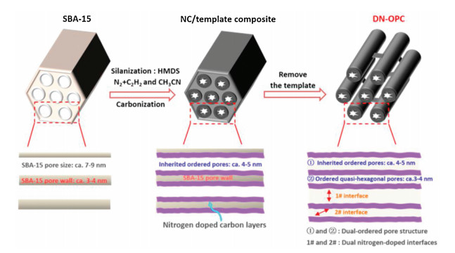
Scheme 1.
Schematic illustration of synthesis of DN-OPC. The detailed chemical reagents and experimental processing are in the supplementary information.
Synthesis of an ordered porous carbon with the dual nitrogen-doped interfaces and its ORR catalysis performance
Hongwei Zhao , Yanqiu Zhang , Li Lixiang , Xin Geng , Haiming Yang , Weimin Zhou , Chengguo Sun , Baigang An

Green and sustainable energy is an issue that human beings have to face in the 21st century. As a green energy conversion and supply device, proton exchange membrane fuel cells (PEMFCs) have advantages of abundant and cheap raw materials, such as air, methanol and hydrogen etc., high conversion efficiency, mild operation temperature and low or zero emissions. Unlike secondary batteries, fuel cells can directly and continuously convert the chemical energy into electric power, they do not have charge-discharge problems so it has been expected for a wide range of applications in power stations, electric vehicles and military industry [1-3]. However, sluggish oxygen reduction reaction (ORR) dynamic is the bottleneck of PEMFCs development [4-6]. Nowadays, the most active catalysts for ORR are still platinum (Pt) based catalysts, but they are overpriced, poor durability and poor methanol tolerance. Therefore, developing novel ORR catalysts owning the advantages of low cost, highly activity and durability, especially metal-free catalysts has great significance on commercialization of PEMFCs [7-9].
Since nitrogen atoms with high electronegativity can activate the neighboring carbon atoms for ORR through electronic interaction of nitrogen-containing functional groups with oxygen, nitrogen-doped porous carbon materials are attracting extensive attentions in the field of ORR catalysts whatever they are used as supports of metal catalysts or as metal-free catalysts [10, 11]. The nitrogen-containing species of porous carbon can enhance the interaction between carbon support and metal catalysts when used as catalyst supports, and weak O—O band and catalyze ORR when used as metal-free catalysts. Meanwhile porous structure of nitrogen-doped porous carbon can influence deposition, distribution of supported catalysts and mass transport during ORR [12, 13]. Therefore, synthesis of nitrogen-doped porous carbon and tuning nitrogen-containing species and pore structure are important aspects in developing ORR catalysts [14-16].
It is generally considered that the larger amount of nitrogen-containing species and the higher specific surface area (SSA) of nitrogen-doped porous carbon catalysts are beneficial to enhance the activity of ORR, however, the utilization of nitrogen-containing species is actually more important for ORR performance [17-21]. It is highly related with the active interfaces that the reagents can easily reach and really interact with. For the porous carbon based catalysts, such interfaces could be constructed by the pore structure facilitating mass transport and the pore surface supplying active sites of nitrogen doping. For example, tedious and disordered pores of carbon materials generally cause catalysts suffered to the problem of mass transport, which can decrease the probability of the interaction between active sites and reagents and thus cut down the catalytic efficiency and performance of catalysts.
Since the ordered pores distributed in three dimensions can facilitate mass transport, many ordered mesoporous carbons comprising the properties of SSA and pore size, have been extensively demonstrated in enhancing mass transport for improving their application in PEMFCs, supercapacitors and lithium ions batteries, etc. [22-25]. Moreover, porous materials owning the complex structure of ordered micro-mesopores [26-28], ordered meso-mesopores [29-31], and ordered meso-macropores [32-34] have been successfully synthesized. Using heteroatomic-doping ordered porous carbons as ORR catalyst, it is highly expected to make more active interfaces while the ordered pores for mass transport are constructed, however, it is hard to achieve this goal.
In this study, a novel carbon based catalyst of ORR that can supply more actives sites by utilizing the dual nitrogen-doped interfaces through the dual-ordered pores has been prepared by a simple one-step CVD of acetylene and acetonitrile vapor using silanized SBA-15 as template. The dual-ordered pore structure facilitates mass transport and the dual nitrogen-doped interfaces make the larger active interfaces. Therefore, as metal-free catalyst for ORR of PEMFCs, this dual-interfaced ordered porous carbon (DN-OPC) exhibits a good performance on ORR. This study supplies a novel strategy for design of ORR catalyst by constructing pore structure and tuning nitrogen-doped interfaces at the same time and thus is promising to develop the porous carbon catalysts with good property.
The schematic illustration of DN-OPC synthesis is shown in Scheme 1. Since the surface chemical inertness for carbon deposition of SBA-15 due to the abundant Si-O containing groups, it needs a surface activation treatment to ensure an efficient carbon deposition onto the pore wall of SBA-15 template. FTIR results of SBA-15 before and after silanization are shown in Fig. 1a. The SBA-15 has several characteristic peaks around 3420, 1053 and 807 cm-1 assigned to the bands of Si—OH, Si—O—Si and Si—O, respectively. These surface groups are inactive for carbon deposition. The peak at 1636 cm-1 is attributed to bending mode of adsorbed water (H2O). For the silanized SBA-15 the peak strength of Si—OH, Si—O, Si—O—Si and adsorbed H2O decreased obviously, respectively. In addition, the C—H band at 2966 cm-1 and Si—C band at 841 cm-1 can be observed [35-37]. Silanization makes the surface of SBA-15 matrix coupled with alkyl owning good activity for carbon deposition in addition to Si—C band. The results indicate that the surface silanization of SBA-15 bring the template the activity of carbon deposition. The effect of silanization on the carbon deposition onto the template can be further confirmed through the thermogravimetric analysis (TGA) of samples prepared by using the SBA-15 template before and after silanization, the results are shown in Fig. 1b. With the same condition of CVD, the amount of carbon deposition on the silanized SBA-15 is up to 21.0 wt%, however, it is only 1.4 wt% for the SBA-15.
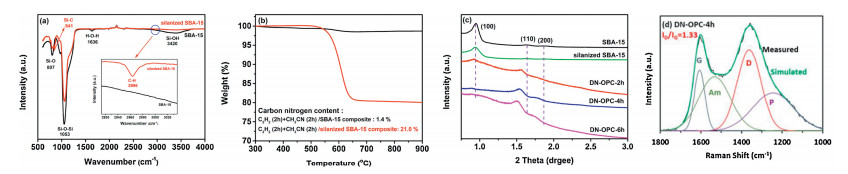
Small-angle XRD tests were used to analyze the pore-structure ordering of the samples and the results are shown in Fig. 1c. The three well-resolved diffraction peaks of DN-OPC samples around 2θ of 0.87°, 1.50° and 1.72° corresponding to (100), (110) and (200) reflections of 2D hexagonal ordered structure can be discerned for both of SBA-15 and the silanized SBA-15 [38, 39], which suggests that the silanization does not change the originally ordered structure of SBA-15. After nitrogen doped carbon coating and subsequent the template remove, the resultant DN-OPC samples still exhibit the ordered structure according to their XRD patterns. However, the characteristic peaks corresponding to the (100), (110) and (200) reflections shift lightly, which could be attributed to the production of new ordered pores and the changes of pore diameter [29]. Unlike the traditional ordered mesoporous carbons with a single type of ordered pore structure [40, 41], the CVD makes the nitrogen-doped carbon layers deposited onto the pore walls of silanized SBA-15 and thus results the pore diameter decrease. On the other hand, after removing the SBA-15 template by HF solution, a new type of ordered pore was produced, the pore size is close to the wall thickness of SBA-15. Therefore, DN-OPC could own the dual-ordered mesoporous structure like the reported in the literature [29] and the illustrated in Scheme 1. The wide-angle XRD patterns of DN-OPC samples are shown in Fig. S1a (Supporting information). It can be found that two broad carbon (002) and (100) peaks appear around 26° and 44°, respectively, the former peak corresponds to the stacking of graphite layers, and the latter corresponds to the domain size of graphite [42]. By comparison, from DN-OPC-2 h to DN-OPC-6 h, the FWHM(002) value decreases in turn as shown in Fig. S1b (Supporting information), and the FWHM(100) values of all DN-OPC samples are similar. The short-time (DN-OPC-2 h) of acetonitrile vapor of CVD process results in a lower number of nitrogenous graphite layers than the long-time CVD. The accumulation degree of graphite layers increases when the time is extended to 4 and 6 h, so the FWHM(002) value of DN-OPC-6 h is slightly lower. The domain size of graphite is similar due to the same post-treatment temperature and time.
Raman spectroscopy is a solid method to identify carbon phases. All of DN-OPC samples showed the graphitic peak (G band) at ca. 1600 cm-1, the structural defects peak (D band) at ca. 1340 cm-1, the peak ascribed to amorphous carbon (Am band) at ca. 1515 cm-1 and the peak ascribed to sp3-bonded carbon atoms (P band) at ca. 1200 cm-1 in Fig. 1d and Fig. S2 (Supporting information) [43]. The relative intensity ratio of D and G band (ID/IG) is proportional to the defects in graphitic carbon, which is often used to characterize the graphitic structure in carbon materials. The DN-OPC-4 h sample has the lowest the ratio of ID/IG indicating its lower defects in graphitic structure among the samples. The graphitization degree of DN-OPC is mainly influenced by the defects resulted by the nitrogen doping and etching [44, 45] and the structural integrity. Despite of middle content of nitrogen, DN-OPC-4 h owns the best integrity from the ordered pore structure, therefore it appears the higher graphitization degree among the samples. However, compared with the classical templated carbons containing one type of ordered pores prepared by polymerization and filling processes [40], DN-OPC prepared by this direct CVD method has a low graphitization degree and relatively more defects.
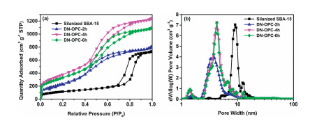
N2 adsorption-desorption isotherms of samples are shown in Fig. 2a. All the samples have the characteristics of type Ⅳ isotherms representing the materials with mesoporous structure [46]. The hysteresis loop of silanized SBA-15 template is in middle-high relative pressure range of P/P0 = 0.7~0.9, however, the relative pressure range of hysteresis for DN-OPC samples decreases to P/P0 = 0.4~0.8. It indicates that the mesopore size of DN-OPC samples become smaller than the template probably due to the carbon coating. Moreover, the adsorption capacity of DN-OPC samples in middle-high relative pressure range becomes much larger than the silanized SBA-15 suggesting the enlarged mesoporous volume produced by removing the pore walls of template. In addition, it can be observed that the DN-OPC samples have the higher adsorption capacity at ultra-low relative pressure of P/P0 < 0.01 than the template, which should be attributed to an increase in microporous volume mainly resulted by the defects during the template etching and nitrogen doping. The pore size distribution (PSD) curves of samples as shown in Fig. 2b further demonstrate the evolution of pore structure. Compared with the template whose mesopores size focusing around 9.0 nm, the focused pore size of DN-OPC samples decreases to around 3.0~5.0 nm due to the carbon coating, meanwhile the microporous volumes increase a lot. Furthermore, the local magnification image of PSD of DN-OPC samples shown in Fig. S3 (Supporting information) indicates that there are two kinds of the focused pore size of 3.0~4.0 nm and 4.0~5.0 nm. Table S1 (Supporting information) gives the parameters of pore and SSA of samples. DN-OPC samples have much larger SSA and pore volume than the silanized SBA-15. Especially, DN-OPC-4 h (the optimized sample prepared by the CVD at 750 ℃ for 4.0 h) owns the highest SSA of 1430 m2/g as more than three times as the template, and pore volume of 1.83 cm3/g. In addition, as the pores of DN-OPC samples consists of a type of cylindrical pores inheriting form the SBA-15 and the other type of pores formed by removing the pore walls of SBA-15, they have significantly larger SSA and pore volume than those mesoporous carbon consisting of only one type of mesopores produced by removing the pore walls of SBA-15 template [46-48].
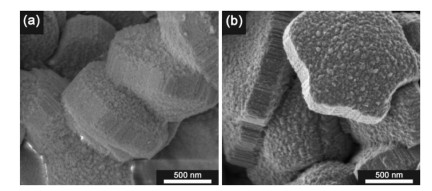
The SEM images of the silanized SBA-15 template and DN-OPC-4 h are shown in Fig. 3. They have similarly particular morphology with arrays of tubular pores, suggesting that the process of silanization, CVD and HF etching to prepare the DN-OPC-4 h sample can still keep and inherit the general morphology of SBA-15. Microstructure of samples was further observed by HRTEM as shown in Fig. 4. In the template of silanized SBA-15 the arrays of cylindrical pores can be clearly observed along the axial direction of particles, the average pore wall thickness is about 3.0~4.0 nm, moreover the pore structure between the neighbored walls can also be discerned (Fig. 4a). Along the cross-section of silanized SBA-15 particles, the ordered arranged pores with diameter of about 7.0~9.0 nm are again confirmed (Fig. 4b). HRTEM of DN-OPC-4 h sample still appears the ordered arranged stripes along the axial direction representing the pores and walls (Fig. 4c). However, it is worthy on noting that there are two types of gray stripes in HRTEM representing the two types of pores. One type of pore represented by the clear and smooth bright gray lines should be produced through etching the pore walls of SBA-15 template, which has a width of about 3.0~4.0 nm. Another type of pore represented by the coarse and thick gray line should derive from the cylindrical pore formed by carbon coating onto the pore wall of silanized SBA-15 template, which has an average diameter of about 4.0~5.0 nm. From the view of cross-section of DN-OPC-4 h (Fig. 4d), the quasi-hexagons showing by bright gray lines with thickness of about 3.0~4.0 nm indicates the pores produced by the removal of template, which is corresponding to and consistent with the observation along the axial direction of sample. However, from the cross-sectional view of sample it is difficult to clearly discern the cylindrical pores formed by carbon coating as shown by the coarse gray stripes in Fig. 4c. Most probably, the carbon coating layers are not complete and have many defects as shown by some tiny bright spots within the quasi-circle, which also results in a lot of micropores as demonstrated by PSD curves of Fig. 2b. For the better understanding, a mesoporous carbon without nitrogen doping was prepared by the direct CVD of acetylene. The HRTEM of Fig. S4 shows a more clear structure of a dual-ordered pores than the DN-OPC-4 h since its low defects.
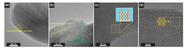
It has been well demonstrated and confirmed by the characterizations of XRD, PSD and HRTEM that there are two types of ordered mesoporous structure and a new formed micropores in the DN-OPC-4 h sample through the process of silanization, CVD of acetylene and acetonitrile vapor, removal of SBA-15 template by HF etching. Especially interesting, these two types of ordered pores are both constructed by the same one wall of pore with the thickness of 3.0~4.0 nm, which results the dual-interfaces in the DN-OPC. One kind of nitrogen doped interface is the side of the wall of cylindrical pore. The other nitrogen doped interface is the side of the wall of quasi-hexagonal pore. Therefore, DN-OPC owns not only the dual-ordered pores but also the dual-interfaces. It is postulated that this dual-ordered pores and dual-interfaces structure will have the more positive effect on mass transfer and efficient utilization of catalytic active sites toward ORR.
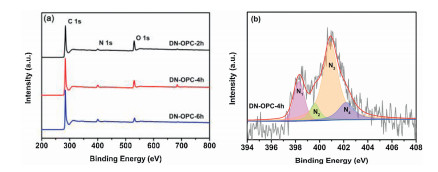
Another critical factor governing ORR activity is the chemical nature of the active sites of catalyst. X-ray photoelectron spectroscopy (XPS) was employed to probe the chemical states of DN-OPC samples. Three characterized peaks observed at 284.6, 400.4 and 532.3 eV of DN-OPC samples in Fig. 5a and are assigned to C 1s, N 1s and O 1s, respectively [49]. It confirms that nitrogen atoms were successfully doped into carbon frameworks by CVD of acetonitrile vapor to form the nitrogen-doped carbon layers. As the pore walls are constructed by these nitrogen-doped carbon layers, DN-OPC owns the dual nitrogen-doped interfaces. The atomic content of C, N and O in DN-OPC samples are listed in Table S2 (Supporting information). The nitrogen content of samples slightly increases with the CVD time. High resolution N 1s spectra (Fig. 5b and Fig. S5 in Supporting information) are deconvoluted into four peaks centered at 398.2, 400.1, 401.0 and 402.1 eV, which can be assigned to pyridinic-N, pyrrolic-N, quaternary-N and oxide pyrinidic-N, respectively [50, 51]. The contents of these types of nitrogen atoms were calculated based on the N 1s spectra and are listed in Table S2. It has been demonstrated that both pyridinic-N and quaternary-N can influence the charge density of adjacent carbon atoms and thus can enhance oxygen adsorption and subsequent catalytic ORR onto the active sites [52-54]. The DN-OPC-4 h has the content of pyridinic-N (0.87 at%) and quaternary-N (1.73 at%) and total nitrogen amount of 4.2 at%. Although total nitrogen amount of DN-OPC-4 h is little less than DN-OPC-6 h (4.9 at%), the content of the pyrinidic-N and quaternary-N contributing the active sites of ORR are very close to the DN-OPC-6 h (0.82 at% and 1.83 at%). Furthermore, ORR activity is not only decided by the content of nitrogen doping, the more important is the utilization of active sites. DN-OPC-4 h has good characteristics of dual-ordered pores, dual-nitrogen doped interfaces and the larger SSA, which could utilize the active site of nitrogen doping more efficiently.
The catalytic ORR performance of DN-OPC samples was firstly evaluated by cyclic voltammetry (CV) in N2 or O2 gas-saturated 0.1 mol/L KOH solution and the results are shown in Fig. 6a. The distinct ORR peaks centered around 0.69, 0.72 and 0.70 V (vs. RHE) of samples from DN-OPC-2 h to DN-OPC-6 h can be observed. The DN-OPC-4 h owns the most positive peak potential of ORR indicating its good ORR performance. It is also found that there are significant the electric double layer capacitance since a large amount of accessible mesopores and high SSA of DN-OPC samples, which makes it difficult to compare the peak current of ORR through CVs. Linear scan voltammetry (LSV) measurements of DN-OPC samples and commercial 20 wt% Pt/C catalyst were then performed and the results are shown in Fig. 6b. Among the DN-OPC samples, the DN-OPC-4 h owns the highest limiting current density close to 20 wt% Pt/C catalyst and relatively positive onset potential for ORR. Despite of a relative low nitrogen doping amount of DN-OPC-4 h compared to the other some nitrogen-doped carbons with the nitrogen doping amount of 5.0~10.0 at% [50-52], the dual-ordered porous structure and dual nitrogen-doped interfaces makes the active sites of nitrogen-containing species more accessible and thus utilized more efficient. Therefore, as metal free catalyst of ORR, DN-OPC-4 h exhibits a good ORR activity close to the commercial Pt/C catalyst. Moreover, by comparing the other nitrogen doped carbons based catalysts, despite of a low content of nitrogen, DN-OPC-4 h still shows an excellent property on ORR as shown in Table S3 (Supporting information).
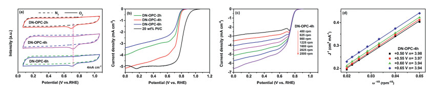
It has been recognized that there are two kinds of ORR catalytic mechanism, one is based on the two-electrons transfer reaction, the other is based on the four-electrons transfer process. The number of electron transfer n can be calculated through K-L equation [52] by using K-L plots of J-1 versus ω-1/2 (Figs. 6c and d, and Fig. S6 in Supporting information) and then is used to postulate the mechanism of ORR. The result shows that the calculated n value of DN-OPC-4 h is 3.94–3.98 from +0.50 V to +0.65 V. To verify the ORR catalytic pathways of these catalysts, the rotating ding disk electrode (RRDE) measurements were further achieved for DN-OPC-4 h (Fig. S7 in Supporting information), carried out to monitor the formation of peroxide species (HO2-) during the ORR process. According to the calculation, the HO2- percentage produced by the DN-OPC-4 h is about 10%. The similar results of RRDE test and K-L equation show that the DN-OPC-4 h is more close to a four-electrons transfer reaction pathway.
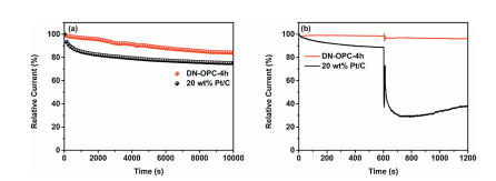
The durability and methanol tolerance of ORR catalysts is also a major concern for application of PEMFC fuel cells technology. The chronoamperometric response of samples in O2-staurated 0.1 mol/L KOH solution is used to evaluated their durability. As shown in Fig. 7a, the ORR current of DN-OPC-4 h keeps 85% of initial value after 10,000 s, which is obviously better than the commercial catalyst of 20 wt% Pt/C having an ORR current retention of 75% under the same operation condition. The good durability of DN-OPC-4 h should be attributed to the dual-ordered mesoporous structure in three dimensions facilitating mass transport, efficient utilizing the active sites of nitrogen-containing species and the closed four electrons transfer route of ORR mechanism. In addition to a good durability, DN-OPC-4 h shows an excellent methanol tolerance as shown in Fig. 7b. There is no obvious change in ORR relative current before and after the introduction of 3 mol/L methanol in 0.1 mol/L KOH solution. However, a dramatic decrease of ORR relative current can be observed for catalyst of 20 wt% Pt/C and the current cannot recover to the previous value before adding methanol.
In summary, DN-OPC that a novel porous carbon with the dual-ordered pores and the dual nitrogen-doped interfaces has been successfully synthesized by developing a one-step CVD of acetylene and acetonitrile vapor using the silanized SBA-15 as template. The optimized sample of DN-OPC owns a large SSA of 1430 m2/g, the dual-ordered mesopores of one type of cylindrical pores and the other type of quasi-hexgonal pores, the highest pore volume of 1.83 cm3/g and nitrogen-containing functional groups of 4.2 at%. As metal free catalyst, the DN-OPC-4 h exhibits a good performance of catalytic ORR close to commercial catalyst of 20 wt% Pt/C through evaluating its onset potential, oxygen diffusion limiting current, durability and methanol tolerance. Good ORR properties of DN-OPC-4 h can be attributed to its dual-ordered pore structure in three-dimensions enhancing mass transport and the dual nitrogen-doped interfaces supplying more active sites, which largely improve the efficient utilization of active sites on ORR. Simple one-step CVD of acetylene and acetonitrile vapor to synthesize DN-OPC and good property of the optimized sample obtained by tuning CVD parameters makes this study promising in designing and developing the heteroatoms-doped porous carbons based catalysts with high catalytic performance of ORR.
The authors declare no competing financial interest.
The financial supports from National Natural Science Foundation of China projects (NSFC, Nos. 51672117, 51672118, 51872131, 51972156 and 21701077) and the Distinguished Professor Project of Education Department of Liaoning and Key Scientific Research Plan of Liaoning Province (No. 2018304017) are acknowledged.
Supplementary material related to this article can be found, in the online version, at doi:https://doi.org/10.1016/j.cclet.2020.11.035.
N. Demirdöven, J. Deutch, Science 305 (2004) 974-976. doi: 10.1126/science.1093965
M.Z. Jacobson, W.G. Colella, D.M. Golden, Science 308 (2005) 1901-1905. doi: 10.1126/science.1109157
R.F. Service, Science 312 (2006) 35.
R.F. Service, Science 315 (2007) 172. doi: 10.1126/science.315.5809.172
W. Li, C.G. Min, F. Tan, et al., ACS Nano 13 (2019) 3177-3187. doi: 10.1021/acsnano.8b08692
A.A. Eissa, S.G. Peera, N.H. Kim, J.H. Lee, J. Mater. Chem. A 7 (2019) 16920-16936. doi: 10.1039/C9TA01837A
H.W. Liang, X.D. Zhuang, S. Brüller, X.L. Feng, K. Müllen, Nat. Commun. 5 (2014) 4973. doi: 10.1038/ncomms5973
T.L. Gong, R.Y. Qi, X.D. Liu, H. Li, Y.M. Zhang, Nano-Micro Lett. 11 (2019) 9. doi: 10.1007/s40820-019-0240-x
A. Zitolo, V. Goellner, V. Armel, et al., Nat. Mater. 14 (2015) 937. doi: 10.1038/nmat4367
Z.S. Wu, L. Chen, J. Liu, et al., Adv. Mater. 26 (2014) 1450-1455. doi: 10.1002/adma.201304147
X.R. Wang, J.Y. Liu, Z.W. Liu, et al., Adv. Mater. 30 (2018) 1800005. doi: 10.1002/adma.201800005
Z. Zhou, A. Chen, X. Fan, A. Kong, Y. Shan, Appl. Surf. Sci. 464 (2019) 380-387. doi: 10.1016/j.apsusc.2018.09.095
S. Jiang, Y.J. Sun, H.C. Dai, et al., Nanoscale 7 (2015) 10584-10589. doi: 10.1039/C5NR01793A
E. Pourazadi, E. Haque, S.N. Faisal, A.T. Harris, Mater. Chem. Phys. 207 (2018) 380-388. doi: 10.1016/j.matchemphys.2017.12.090
N. Jia, Q. Weng, Y.R. Shi, et al., Nano Res. 11 (2018) 1905-1916. doi: 10.1007/s12274-017-1808-8
S.Q. Feng, C. Liu, Z.G. Chai, Q. Li, D.S. Xu, Nano Res. 11 (2018) 1482-1489. doi: 10.1007/s12274-017-1765-2
M.M. Wu, K. Wang, M. Yi, et al., ACS Catal. 7 (2017) 6082-6088. doi: 10.1021/acscatal.7b01649
X.J. Bo, C. Han, Y.F. Zhang, L.P. Guo, ACS Appl. Mater. Interfaces 6 (2014) 3023-3030. doi: 10.1021/am405609d
H.W. Zhao, L.L. Li, Y.Y. Liu, et al., Appl. Surf. Sci. 504 (2020)144438. doi: 10.1016/j.apsusc.2019.144438
S.W. Han, J. Bang, S.H. Ko, R. Ryoo, J. Mater. Chem. A 7 (2019) 8353-8360. doi: 10.1039/C9TA01621J
M. Sun, X.B. Wu, Z.Y. Xie, et al., Carbon 125 (2017) 401-408. doi: 10.1016/j.carbon.2017.09.085
R.H. Xing, T.S. Zhou, Y. Zhou, et al., Nano-Micro Lett. 10 (2018) 3. doi: 10.1007/s40820-017-0157-1
J. Liu, X.X. Wu, L.P. Yang, F. Wang, J. Yin, Electrochim. Acta 297 (2019) 539-544. doi: 10.1016/j.electacta.2018.12.017
X.Q. Zhang, A.H. Lu, Q. Sun, et al., ACS Appl. Energy Mater. Interfaces 1 (2018) 5999-6005. doi: 10.1021/acsaem.8b01051
H. Jung, J. Shin, C. Chae, J.K. Lee, J. Kim, J. Phy. Chem. C 117 (2013) 14939-14946. doi: 10.1021/jp4023162
M. Enterría, F. Suárez-García, A. Martínez-Alonso, J.M.D. Tascón, Microporous Mesoporous Mater. 151 (2012) 390-396. doi: 10.1016/j.micromeso.2011.10.004
N. Petkov, M. Hölzl, T.H. Metzger, S. Mintova, T. Bein, J. Phy. Chem. B 109 (2005) 4485-4491. doi: 10.1021/jp0444969
S. Zhao, X.L. Sheng, Y.M. Zhou, et al., J. Porous. Mater 22 (2015) 1407-1416. doi: 10.1007/s10934-015-0020-z
S.H. Joo, S.J. Choi, I. Oh, et al., Nature 412 (2001) 169-172. doi: 10.1038/35084046
Y. Wang, K.Y. Wang, R. Zhang, et al., ACS Nano 8 (2014) 7870-7879. doi: 10.1021/nn5027214
J.K. Hu, M. Noked, E. Gillette, et al., J. Mater. Chem. A 3 (2015) 21501-21510. doi: 10.1039/C5TA06372H
H. Yamada, H. Nakamura, F. Nakahara, I. Moriguchi, T. Kudo, J. Phy. Chem. C 111 (2007) 227-233.
L.C. Cao, Y. Shi, J.Q. Geng, D. Yang, Mater. Chem. Phys. 130 (2011) 1280-1286. doi: 10.1016/j.matchemphys.2011.09.015
C.F. Xue, B. Tu, D.Y. Zhao, Adv. Funct. Mater. 18 (2008) 3914-3921. doi: 10.1002/adfm.200800708
T. Kaneko, D. Nemoto, A. Horiguchi, N. Miyakawa, J. Cryst. Growth 275 (2005) 1097-1101. doi: 10.1016/j.jcrysgro.2004.11.128
Y. Fang, P. Lakey, S. Riahi, et al., Chem. Sci. 10 (2019) 2906-2914. doi: 10.1039/C8SC05560B
J. Percino, J.A. Pacheco, G. Soriano-Moro, et al., RSC Adv. 5 (2015) 79829-79844. doi: 10.1039/C5RA10056A
T.Q. Lin, I.W. Chen, F.X. Liu, et al., Science 350 (2015) 1508. doi: 10.1126/science.aab3798
R. Liu, D. Wu, X. Feng, K. Mullen, Angew. Chem. Int. Ed. 49 (2010) 2565-2569. doi: 10.1002/anie.200907289
P. Janus, R. Janus, B. Dudek, et al., Microporous Mesoporous Mater. 299 (2020) 110118. doi: 10.1016/j.micromeso.2020.110118
J.Y. Cheon, C. Ahn, D.J. You, et al., J. Mater. Chem. A 1 (2012) 1270-1283.
H. Nishihara, T. Simura, S. Kobayashi, et al., Adv. Funct. Mater. 26 (2016) 6418-6427. doi: 10.1002/adfm.201602459
R. Tang, K. Taguchi, H. Nishihara, et al., J. Mater. Chem. A 7 (2019) 7480-7488. doi: 10.1039/C8TA11005K
Q.H. Yang, P.X. Hou, M. Unno, et al., Nano Lett. 5 (2005) 2465-2469. doi: 10.1021/nl051779j
Y. Li, H. Li, A. Petz, S. Kunsági-Máté, Carbon 93 (2015) 515-522. doi: 10.1016/j.carbon.2015.05.068
A.G. Kong, X.F. Zhu, Z. Han, et al., ACS Catal. 4 (2014) 1793-1800. doi: 10.1021/cs401257j
D.S. Yang, D. Bhattacharjya, S. Inamdar, J. Park, J.S. Yu, J. Am. Chem. Soc. 134 (2012) 16127-16130. doi: 10.1021/ja306376s
X.X. Zhang, J.P. He, T. Wang, et al., J. Mater. Chem. A 2 (2014) 3072-3082. doi: 10.1039/c3ta13732e
K. Mamtani, D. Jain, D. Dogu, et al., Appl. Catal. B-Environ. 220 (2018) 88-97. doi: 10.1016/j.apcatb.2017.07.086
J.C. Li, S.Y. Zhao, P.X. Hou, et al., Nanoscale 7 (2015) 19201-19206. doi: 10.1039/C5NR05998D
S. Ratso, N. Ranjbar Sahraie, M.T. Sougrati, et al., J. Mater. Chem. A 6 (2018) 14663-14674. doi: 10.1039/C8TA02325E
B.H. Zhang, C.P. Wang, D. Liu, et al., ACS Sustain. Chem. Eng. 6 (2018) 13807-13812. doi: 10.1021/acssuschemeng.8b01876
H.W. Zhao, T.Y. Xing, L.X. Li, et al., Int. J. Hydrog. Energy 44 (2019) 25180-25187. doi: 10.1016/j.ijhydene.2019.03.271
J.J. Wu, L.L. Ma, R.M. Yadav, et al., ACS Appl. Mater. Interfaces 7 (2015) 14763-14769. doi: 10.1021/acsami.5b02902

Scheme 1 Schematic illustration of synthesis of DN-OPC. The detailed chemical reagents and experimental processing are in the supplementary information.

Figure 1 (a) FTIR spectra of the SBA-15 and the silanized SBA-15. (b) TG curves of the SBA-15 and the silanized SBA-15 treated by CVD of acetylene and acetonitrile vapor with 2 h. (c) Small-angle XRD of samples. (d) Deconvoluted components (D, G, P, Am), fitting result and the values of ID/IG are shown for DN-OPC-4 h. The inset of (a) represent the magnified peak of FTIR spectra.

Figure 2 (a) N2 adsorption-desorption isotherms and (b) DFT pore size distribution of silanized SBA-15 and DN-OPC samples.

Figure 4 HRTEM images and observation along the axial direction of silanized (a) SBA-15 and (c) DN-OPC-4 h, and viewed along cross-section of silanized (b) SBA-15 and (d) DN-OPC-4 h. The inset of (c, d) represent the similar structure schematic.

Figure 5 (a) XPS survey spectra of DN-OPC samples. (b) High-resolution N 1s XPS spectra of DN-OPC-4h. N1: Pyridinic-N; N2: Pyrrolic-N; N3: Quaternary-N; N4: Oxide pyridinic-N.

Figure 6 (a) CV curves of DN-OPC samples. (b) LVS curves of DN-OPC samples and 20 wt% Pt/C at rotation rate of 1600 rpm. (c) LSV curves of DN-OPC-4 h at rotation rate of 400 rpm to 2500 rpm. (d) Koutecky-Levich plots obtained from DN-OPC-4 h at different potentials.

Figure 7 (a) Chronoamperometric responses of the DN-OPC-4 h and 20 wt% Pt/C at +0.5 V vs. RHE with rotation rate of 900 rpm. (b) The DN-OPC-4 h and 20 wt% Pt/C catalysts kept at +0.5 V vs. RHE when 3 mol/L methanol was added at 600 s with rotation rate of 900 rpm in O2-staurated 0.1 mol/L KOH solution.

 扫一扫看文章

扫一扫关注我们
 DownLoad:
 下载:
下载:

 下载:
下载: