 图1
PET基底上制备的AgNWs网状结构(A)和APA复合薄膜(B)的扫描电子显微镜照片
Figure1.
SEM images of the pristine AgNW network(A) and the APA composite film(B) prepared on the PET substrates
图1
PET基底上制备的AgNWs网状结构(A)和APA复合薄膜(B)的扫描电子显微镜照片
Figure1.
SEM images of the pristine AgNW network(A) and the APA composite film(B) prepared on the PET substrates
引用本文:
张晓琴, 吴江, 王建太, 闫驰, 付莹莹, 谢志元. 基于银纳米线复合透明电极的可弯折柔性聚合物太阳能电池[J]. 应用化学,
2018, 35(1): 109-115.
doi:
10.11944/j.issn.1000-0518.2018.01.170025

Citation: ZHANG Xiaoqin, WU Jiang, WANG Jiantai, YAN Chi, FU Yingying, XIE Zhiyuan. Silver Nanowire Composite Transparent Electrode Based Flexible Polymer Solar Cells[J]. Chinese Journal of Applied Chemistry, 2018, 35(1): 109-115. doi: 10.11944/j.issn.1000-0518.2018.01.170025
Citation: ZHANG Xiaoqin, WU Jiang, WANG Jiantai, YAN Chi, FU Yingying, XIE Zhiyuan. Silver Nanowire Composite Transparent Electrode Based Flexible Polymer Solar Cells[J]. Chinese Journal of Applied Chemistry, 2018, 35(1): 109-115. doi: 10.11944/j.issn.1000-0518.2018.01.170025
基于银纳米线复合透明电极的可弯折柔性聚合物太阳能电池
摘要:
本文设计了一种可以通过刮涂方法制备的基于银纳米线(AgNWs)的柔性复合透明电极,并以此为基础实现了高性能柔性聚合物太阳能电池的制备。基于银纳米线的柔性复合薄膜(APA)由银纳米线(AgNWs),聚乙烯醇缩丁醛(PVB)和铝掺杂氧化锌(AZO)纳米粒子在低温下通过多层刮涂的方法制备。APA透明复合薄膜在550 nm处透光率达到90.90%,面电阻低至13.01 Ω/sq,在柔性基底上具有很高的粘附性。在透明的APA/聚对苯二甲酸乙二醇酯(PET)基底上制备的柔性聚合物太阳能电池(PSCs),能量转换效率达到5.47%。而且以5 mm为曲率半径,经过1000次循环弯曲实验,电池的能量转换效率仅下降了14%。
English
Silver Nanowire Composite Transparent Electrode Based Flexible Polymer Solar Cells
Abstract:
A high performance flexible polymer solar cells(PSCs) are obtained by using a flexible, transparent composite electrode based on silver nanowire(AgNW) with doctor blading method. The AgNW-based flexible composite film(APA) consisting of AgNWs, polyvinyl butyral(PVB) and Al-doped ZnO(AZO) nanoparticles was readily prepared by multi-layer doctor blading on the poly(ethylene terephthalate)(PET) substrate at moderate temperature. The transparent APA composite film prepared on the PET substrate exhibits superior opto-electrical properties with a high transmittance of 90.90% at 550 nm and a low sheet resistance of 13.01 Ω/sq. The flexible PSCs employing the transparent APA/PET substrate obtain power convention efficiency(PCE) of 5.47%. Moreover, the PCE falls only 14% after bending for 1000 cycles with a bending radius of 5 mm.
-
Key words:
- silver nanowires
- / composite electrode
- / flexible
- / polymer solar cells
-
目前,聚合物太阳能电池(PSCs)的能量转化效率已经超过10%,有望实现商业化生产[1-6]。但是对于roll-to-roll方法制备可弯折的PSCs而言,柔性透明电极是首先要解决的问题[7-9]。目前,所用的柔性透明电极主要是在柔性基底,如聚对苯二甲酸乙二酯(PET)真空溅射的铟锡氧化物(ITO)[10]。ITO在可见光下具有很高的透过率,并且导电性高,但是ITO价格昂贵,质脆,而且需要在高真空下高温溅射制备,不适用于大面积柔性PSCs的制备[11-13]。目前,报道的ITO替代物有碳纳米管[14-16]、石墨烯[17-19]、导电聚合物[20-22]和金属纳米线或格栅[23-26]。其中,金属纳米线,主要是银纳米线(AgNWs),由于其可弯折性高,具有和ITO相当的光电学性质,已成为最具潜力的ITO替代材料[27-29]。在制备AgNWs电极的过程中一般都会用一些方法,例如热退火、施加外力、真空过滤、焦耳热退火和等离子体焊接等降低线与线之间的接触电阻,提高电导率[30-36],但是这些方法不适用于柔性或者大面积PSCs的制备,柔性AgNWs薄膜一般都是从刚性基底转移制备得到,使得器件制备过程复杂化[29]。本文用AgNWs、聚乙烯醇缩丁醛(PVB)和铝掺杂氧化锌(AZO)纳米粒子在低温下,通过多层刮涂的方法在PET基底上制备了一种复合电极(APA),该柔性复合电极具有很高的光电性质,对基底有很强的粘附性,以其为电极制备的柔性聚合物太阳能器件比柔性ITO做电极的器件性能高,而且器件在弯折测试过程中具有更高的稳定性。
1 实验部分
1.1 仪器和试剂
KDY-1型四探针(广东市昆德科技有限公司);UV-3600 UV-VIS-NIR型的分光光度计(日本岛津国际贸易有限公司);XL-30 ESEM FEG SEM FEI COMPANYTM型的扫描电子显微镜(新西兰Philips公司);Zeiss Axio Imager A2m型的光学显微镜(德国卡尔蔡司公司)。Enlitech QE-R3011光谱响应系统(光焱科技股份有限公司)。
AgNWs分散液购自美国Blue Nano公司,直径约35 nm,长度大于20 μm,分散在乙醇中,质量浓度为10 g/L。poly[N-9″-hepta-decanyl-2, 7-carbazole-alt-5, 5-(4′, 7′-dithienyl-2′, 1′, 3′-benzothiadiazole)](PCDTBT)是本实验室合成的,质均相对分子质量为24000,相对分子质量分布系数为1.8。[6, 6]-phenyl C71-butyric acid methyl ester(PC71BM, >99%)购自美国染料公司,PVB(航空级)购自国药集团化学试剂有限公司。粒径约5 nm的ZnO纳米粒子通过Beek等[37]报道的方法制备得到,粒径4~8 nm的AZO纳米粒子通过Zhang等[38]报道的方法制备,分散在乙醇中并且溶液质量浓度为15 g/L。
1.2 柔性PET基底上APA复合薄膜的制备
复合薄膜的制备过程与我们组报道的在玻璃基底上的制备方法[39]相同,AgNWs分散液稀释至5 g/L,将50 g/L的PVB乙醇溶液加入其中,V(AgNWs):V(PVB)=7:1,AgNWs分散液在使用之前必须充分摇匀。首先,将100 μL AgNWs与PVB的混合溶液滴加在预先清洗干净的PET基底上,在50 ℃下,以35 mm/s的刮涂速率制备AgNWs-PVB薄膜,5 min后,在预先制备的薄膜上滴加100 μL AZO纳米粒子,以20 mm/s的刮涂速率制备一层AZO薄膜,重复相同的AZO薄膜制备过程3次,得到由AgNWs、PVB和AZO组成的APA复合薄膜。
1.3 柔性PSCs的制备
柔性聚合物太阳能电池以PET基底上的APA复合薄膜为阴极,参比器件以PET基底上的ITO为阴极,其中ITO/PET的面电阻为31 Ω/sq,使用前在丙酮和异丙醇中各超声15 min,用去离子水冲洗干净,120 ℃,烘烤1 h,之后紫外臭氧处理25 min。将ZnO纳米粒子溶液旋涂在PET基底上的两种电极表面,膜厚为25 nm。然后将基板转移至含高纯氮的手套箱中旋涂制备活性层。活性层由3.5 g/L的给体材料PCDTBT和14 g/L的受体材料PC71BM在邻二氯苯中的混合溶液旋涂制备,厚度为80 nm。最后在4×10⁻⁴ Pa真空下,将12 nm的MoO3和100 nm Al依次蒸镀上去,完成器件的制备,器件面积为12.56 mm2。
1.4 导电薄膜表征和PSCs测试方法
导电薄膜的面电阻由KDY-1型四探针测量;光学透过率由分光光度计测量;扫描电子显微镜照片由扫描电子显微镜在20 kV的加速电压下获得。Newport自带AM 1.5 G滤光片的太阳光模拟器用来提供100 mW/cm的模拟太阳光,光强度由带KG-5可见光滤光片的标准硅电池校准,器件的电流-电压曲线由联接计算机的Keithley 2400源表采集,外量子效率由Enlitech QE-R光谱响应系统在短路情况下获得。
2 结果与讨论
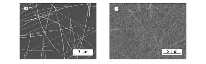
图 1是在PET基底上刮涂制备的AgNWs和APA复合薄膜的扫描电子显微镜照片,如图 1A所示。可见,AgNWs疏松地分散在PET基底上,这样会导致纳米线与线之间接触不紧密,接触电阻很大,所以薄膜的面电阻也很高。对于图 1B中的APA复合薄膜,由于PVB和PET基底具有很高的相容性,能够将AgNWs粘附在基底上,AZO纳米粒子有效地填充了AgNWs之间的空隙,最后得到光滑均匀的薄膜。
图1
PET基底上制备的AgNWs网状结构(A)和APA复合薄膜(B)的扫描电子显微镜照片
Figure1.
SEM images of the pristine AgNW network(A) and the APA composite film(B) prepared on the PET substrates
图 2是AgNWs和APA复合薄膜在PET基底上的透射光谱图,并与PET基底上的ITO做对比。在350~800 nm处,AgNWs和APA复合薄膜均有较高的透光率,而且在350~500 nm处的透光率高于ITO。AgNWs在550 nm处的透光率为91.71%,APA复合薄膜略微降至90.90%,透光率的变化归因于AZO纳米粒子的吸收和反射效应[40]。在PET基底上的ITO薄膜,面电阻为31 Ω/sq,AgNWs由于相互之间接触疏松,面电阻很高而不易测得,而对于APA复合薄膜,面电阻降至13.01 Ω/sq,主要是由于AZO纳米粒子能够使纳米线之间接触紧密,降低了面电阻。
 图2
PET基底上AgNWs和APA复合薄膜以及ITO的透射光谱图
Figure2.
Transmittance spectra of the pristine AgNWs and the APA composite film on PET substrates together with the commercial ITO/PET substrate
图2
PET基底上AgNWs和APA复合薄膜以及ITO的透射光谱图
Figure2.
Transmittance spectra of the pristine AgNWs and the APA composite film on PET substrates together with the commercial ITO/PET substrate
在柔性PSCs的制备过程中,透明底电极与柔性衬底间较高的附着力,可以保证在其上层进行溶液加工时,电极不被破坏,可以提高器件性能和稳定性。对于PET基底上的AgNWs薄膜,由于和PET之间的相互作用力很弱,很容易被破坏,而对于PET基底上的APA复合薄膜,由于PVB的引入能够增大AgNWs对基底的粘附性,图 3是APA复合薄膜的面电阻随3M胶带粘撕次数的变化,结果表明,在500次循环粘撕实验后,APA复合薄膜的面电阻几乎没有变化。
 图3
PET基底上的APA复合薄膜的面电阻随3M胶带粘撕次数的变化
Figure3.
The sheet resistance values of the APA composite film coated on the flexible PET substrate as a function of taping times using 3M Scotch tape
图3
PET基底上的APA复合薄膜的面电阻随3M胶带粘撕次数的变化
Figure3.
The sheet resistance values of the APA composite film coated on the flexible PET substrate as a function of taping times using 3M Scotch tape
我们将这种柔性透明电极基板应用到柔性PSCs中,制备了以PCDTBT为给体,PC71BM为受体的柔性倒置结构光伏器件。器件结构如图 4A所示,从下至上分别为PET/ITO或APA复合薄膜/ZnO/活性层/MoO3/Al,图 4B是制备得到的基于APA透明电极的柔性聚合物太阳能电池实物图。图 4C和4D分别是柔性光伏器件的电流-电压曲线和外量子效率(EQE)曲线。对于APA复合薄膜做电极的器件,开路电压为0.89 V,短路电流为10.11 mA/cm2,填充因子为61.09%,最终的能量转化效率为5.47%,而ITO做电极的柔性器件,开路电压为0.89 V,短路电流为9.57 mA/cm2,填充因子为60.54%,最终的能量转化效率为5.16%。APA复合薄膜做电极的器件具有更优的光伏性能,其具有较高的短路电流值,而这一点也可以通过EQE曲线得到证明。如图 4D所示,在350~450 nm处,APA复合薄膜做电极的柔性器件EQE比ITO做电极的柔性器件高,归因于在350~500 nm处APA复合薄膜更高的光透过率,如图 2所示。
 图4
在PET基底上制备的采用APA复合薄膜和ITO做电极的聚合物太阳能电池结构图(A);制备的柔性聚合物太阳能电池照片(B);以APA复合薄膜和ITO做透明电极的柔性器件的亮态电流-电压曲线(C)和外量子效率曲线(D)
Figure4.
Device architecture of the flexible PSCs based on the APA composite or ITO-coated PET substrates(A); A picture of flexible PSCs fabricated on the APA/PET substrate(B); The illuminated J-V curves(C) and (D)the EQE spectra of the flexible PSCs fabricated on the PET substrates employing the APA composite and ITO as the transparent cathode, respectively
图4
在PET基底上制备的采用APA复合薄膜和ITO做电极的聚合物太阳能电池结构图(A);制备的柔性聚合物太阳能电池照片(B);以APA复合薄膜和ITO做透明电极的柔性器件的亮态电流-电压曲线(C)和外量子效率曲线(D)
Figure4.
Device architecture of the flexible PSCs based on the APA composite or ITO-coated PET substrates(A); A picture of flexible PSCs fabricated on the APA/PET substrate(B); The illuminated J-V curves(C) and (D)the EQE spectra of the flexible PSCs fabricated on the PET substrates employing the APA composite and ITO as the transparent cathode, respectively
我们对不同透明电极的柔性PSCs做了弯折性实验,曲率半径固定为0.5 cm,图 5是柔性器件光伏性能参数随弯折次数变化的曲线。实验表明,对于ITO做电极的柔性器件,随着弯折次数的增加,器件性能急剧降低,经过200次循环弯折实验后,器件失去光伏效应。而APA复合薄膜做电极的器件,器件性能随着弯折次数的增大缓慢降低,经过1000次循环弯折实验后,器件的能量转化效率为弯折前的86%,这一测试结果表明,以APA复合薄膜为电极的柔性器件比以ITO为电极的柔性器件具有更高的可弯折性。柔性器件的可弯折性与电极的性质紧密相关,如图 6所示,由于ITO质脆,在弯曲实验中面电阻急剧增大,光学显微镜图可以看出,经过循环弯曲实验后,在PET基底上的ITO薄膜出现大量裂纹,ITO导电性显著降低,而对于APA复合薄膜,经过1000次循环弯曲实验后,面电阻几乎没有变化,薄膜表面没有明显的变化,说明APA复合薄膜具有很高的力学稳定性。
 图5
PET基底上制备的以APA复合薄膜和ITO做电极的柔性聚合物太阳能电池的短路电流(A)、开路电压(B)、填充因子(C)和能量转化效率(D)随弯折次数的变化,曲率半径为5 mm
Figure5.
The changes of JSC(A), VOC(B), FF(C) and PCE(D) of the flexible PSCs fabricated on the APA and the ITO-coated PET substrate as a function of bending cycles with a bending radius of 5 mm
图5
PET基底上制备的以APA复合薄膜和ITO做电极的柔性聚合物太阳能电池的短路电流(A)、开路电压(B)、填充因子(C)和能量转化效率(D)随弯折次数的变化,曲率半径为5 mm
Figure5.
The changes of JSC(A), VOC(B), FF(C) and PCE(D) of the flexible PSCs fabricated on the APA and the ITO-coated PET substrate as a function of bending cycles with a bending radius of 5 mm
 图6
PET基底上的APA复合薄膜和ITO的面电阻随弯折次数的变化,曲率半径为5 mm。插图为弯折后ITO(左)和APA复合薄膜(右)的光学显微镜图
Figure6.
The sheet resistance changes of the APA/PET substrate and the commercial ITO/PET substrate as a function of the bending numbers with a bending radius of 5 mm. Insets are the optical images of ITO/PET(left) and APA/PET(right) after the bending test
图6
PET基底上的APA复合薄膜和ITO的面电阻随弯折次数的变化,曲率半径为5 mm。插图为弯折后ITO(左)和APA复合薄膜(右)的光学显微镜图
Figure6.
The sheet resistance changes of the APA/PET substrate and the commercial ITO/PET substrate as a function of the bending numbers with a bending radius of 5 mm. Insets are the optical images of ITO/PET(left) and APA/PET(right) after the bending test
3 结论
本文通过溶液加工的方法在聚对苯二甲酸乙二酯(PET)基底上制备了一种柔性透明导电薄膜,该薄膜是由银纳米线(AgNWs)、聚乙烯醇缩丁醛(PVB)和铝掺杂氧化锌(AZO)纳米粒子在50 ℃下通过多层刮涂制备得到。这种基于AgNWs的透明导电复合薄膜具有很高的透光率和良好的导电性,同时复合薄膜对PET基底还有很强的粘附性。将这种柔性透明薄膜用作透明电极制备柔性聚合物太阳能电池,器件光伏性能比柔性ITO做电极的器件性能高,而且该柔性器件具有更高的可弯折性。研究结果表明,这种低温下溶液加工的AgNWs复合透明电极有望未来应用到印刷制备大尺寸柔性聚合物薄膜太阳能电池中。
-
-
[1]
You J, Dou L, Yoshimura K. A Polymer Tandem Solar Cell with 10.6% Power Conversion Efficiency[J]. Nat Commun, 2013, 4(1446): 1446.
-
[2]
Tang C W. Two-Layer Organic Photovoltaic Cell[J]. Appl Phys Lett, 1986, 48(2): 183-185. doi: 10.1063/1.96937
-
[3]
Sun K, Zhao B, Kumar A. Highly Efficient, Inverted Polymer Solar Cells with Indium Tin Oxide Modified with Solution-Processed Zwitterions as the Transparent Cathode[J]. ACS Appl Mater Interfaces, 2012, 4(4): 2009-2017. doi: 10.1021/am201844q
-
[4]
Small C E, Chen S, Subbiah J. High-Efficiency Inverted Dithienogermole-Thienopyrrolodione-Based Polymer Solar Cells[J]. Nat Photon, 2011, 6(2): 115-120.
-
[5]
Liu Y, Zhao J, Li Z. Aggregation and Morphology Control Enables Multiple Cases of High-Efficiency Polymer Solar Cells[J]. Nat Commun, 2014, 5(5): 5293.
-
[6]
Liang Y, Xu Z, Xia J. For the Bright Future-Bulk Heterojunction Polymer Solar Cells with Power Conversion Efficiency of 7.4%[J]. Adv Mater, 2010, 22(20): E135-138. doi: 10.1002/adma.200903528
-
[7]
Søndergaard R, Hösel M, Krebs F C. Roll-to-Roll Fabrication of Large Area Functional Organic Materials[J]. J Polym Sci Part B:Polym Phys, 2013, 51(3): 16-34.
-
[8]
S ndergaard R, H sel M, Angmo D. Roll-to-Roll Fabrication of Polymer Solar Cells[J]. Mater Today, 2012, 15(1/2): 36-49.
-
[9]
Forrest S R. The Path to Ubiquitous and Low-Cost Organic Electronic Appliances on Plastic[J]. Nature, 2004, 428(6986): 911-918. doi: 10.1038/nature02498
-
[10]
Cairns D R, Crawford G P. Electromechanical Properties of Transparent Conducting Substrates for Flexible Electronic Displays[J]. Proc IEEE, 2005, 93(8): 1451-1458. doi: 10.1109/JPROC.2005.851515
-
[11]
Ye S, Rathmell A R, Chen Z. Metal Nanowire Networks:The Next Generation of Transparent Conductors[J]. Adv Mater, 2014, 26(39): 6670-6687. doi: 10.1002/adma.v26.39
-
[12]
Inganas O. Organic Photovoltaics Avoiding Indium[J]. Nat Photon, 2011, 5(4): 201-202. doi: 10.1038/nphoton.2011.46
-
[13]
Chipman A. A Commodity No More[J]. Nature, 2007, 449(7159): 131-131. doi: 10.1038/449131a
-
[14]
Tenent R C, Barnes T M, Bergeson J D. Ultrasmooth, Large-Area, High-Uniformity, Conductive Transparent Single-Walled-Carbon-Nanotube Films for Photovoltaics Produced by Ultrasonic Spraying[J]. Adv Mater, 2009, 21(31): 3210-3216. doi: 10.1002/adma.v21:31
-
[15]
Gruner G. Carbon Nanotube Films for Transparent and Plastic Electronics[J]. J Mater Chem, 2006, 16(35): 3533-3539. doi: 10.1039/b603821m
-
[16]
Cao Q, Hu S H, Zhu Z T. Highly Bendable, Transparent Thin-Film Transistors that Use Carbon-Nanotube-Based Conductors and Semiconductors with Elastomeric Dielectrics[J]. Adv Mater, 2006, 18(3): 304-309. doi: 10.1002/(ISSN)1521-4095
-
[17]
Kim K, Bae S H, Toh C T. Ultrathin Organic Solar Cells with Graphene Doped by Ferroelectric Polarization[J]. ACS Appl Mater Interfaces, 2014, 6(5): 3299-3304. doi: 10.1021/am405270y
-
[18]
Hwang J O, Park J S, Choi D S. Workfunction-Tunable, N-Doped Reduced Graphene Transparent Electrodes for High-Performance Polymer Light-Emitting Diodes[J]. ACS Nano, 2012, 6(1): 159-167. doi: 10.1021/nn203176u
-
[19]
Bult J B, Crisp R, Perkins C L. Role of Dopants in Long-Range Charge Carrier Transport for p-Type and n-Type Graphene Transparent Conducting Thin Films[J]. ACS Nano, 2013, 7(8): 7251-7261. doi: 10.1021/nn402673z
-
[20]
Vosgueritchian M, Lipomi D J, Bao Z. Highly Conductive and Transparent PEDOT:PSS Films with a Fluorosurfactant for Stretchable and Flexible Transparent Electrodes[J]. Adv Funct Mater, 2012, 22(2): 421-428. doi: 10.1002/adfm.201101775
-
[21]
Hu Z, Zhang J, Zhu Y. Effects of Solvent-Treated PEDOT:PSS on Organic Photovoltaic Devices[J]. Renew Energy, 2014, 62(3): 100-105.
-
[22]
Bubnova O, Khan Z U, Wang H. Semi-Metallic Polymers[J]. Nat Mater, 2014, 13(2): 190-194. doi: 10.1038/nmat3824
-
[23]
Rathmell A R, Wiley B J. The Synthesis and Coating of Long, Thin Copper Nanowires to Make Flexible, Transparent Conducting Films on Plastic Substrates[J]. Adv Mater, 2011, 23(41): 4798-4803. doi: 10.1002/adma.201102284
-
[24]
Liang J, Li L, Tong K. Silver Nanowire Percolation Network Soldered with Graphene Oxide at Room Temperature and Its Application for Fully Stretchable Polymer Light Emitting Diodes[J]. ACS Nano, 2014, 8(2): 1590-1600. doi: 10.1021/nn405887k
-
[25]
Im H G, Jung S H, Jin J. Flexible Transparent Conducting Hybrid Film Using a Surface-Embedded Copper Nanowire Network:A Highly Oxidation-Resistant Copper Nanowire Electrode for Flexible Optoelectronics[J]. ACS Nano, 2014, 8(10): 10973-10979. doi: 10.1021/nn504883m
-
[26]
Ghosh D S, Chen T L, Mkhitaryan V. Ultrathin Transparent Conductive Polyimide Foil Embedding Silver Nanowires[J]. ACS Appl Mater Interfaces, 2014, 6(23): 20943-20948. doi: 10.1021/am505704e
-
[27]
Song M, You D S, Lim K. Highly Efficient and Bendable Organic Solar Cells with Solution-Processed Silver Nanowire Electrodes[J]. Adv Funct Mater, 2013, 23(34): 4177-4184. doi: 10.1002/adfm.v23.34
-
[28]
Zhu R, Chung C H, Cha K C. Fused Silver Nanowires with Metal Oxide Nanoparticles and Organic Polymers for Highly Transparent Conductors[J]. ACS Nano, 2011, 5(12): 9877-9882. doi: 10.1021/nn203576v
-
[29]
Gaynor W, Burkhard G F, McGehee M D. Smooth Nanowire/Polymer Composite Transparent Electrodes[J]. Adv Mater, 2011, 23(26): 2905-2910. doi: 10.1002/adma.v23.26
-
[30]
Lee J Y, Connor S T, Cui Y. Solution-Processed Metal Nanowire Mesh Transparent Electrodes[J]. Nano Lett, 2008, 8(2): 689-692. doi: 10.1021/nl073296g
-
[31]
Lee S J, Kim Y H, Kim J K. A Roll-to-Roll Welding Process for Planarized Silver Nanowire Electrodes[J]. Nanoscale, 2014, 6(20): 11828-11834. doi: 10.1039/C4NR03771E
-
[32]
Ho X, Tey J, Liu W. Biaxially Stretchable Silver Nanowire Transparent Conductors[J]. J Appl Phys, 2013, 113(4): 044311. doi: 10.1063/1.4789795
-
[33]
Bergin S M, Chen Y H, Rathmell A R. The Effect of Nanowire Length and Diameter on the Properties of Transparent, Conducting Nanowire Films[J]. Nanoscale, 2012, 4(6): 1996-2004. doi: 10.1039/c2nr30126a
-
[34]
Song T B, Chen Y, Chung C H. Nanoscale Joule Heating and Electromigration Enhanced Ripening of Silver Nanowire Contacts[J]. ACS Nano, 2014, 8(3): 2804-2811. doi: 10.1021/nn4065567
-
[35]
Li J, Zhang W, Li Q. Excitation of Surface Plasmons from Silver Nanowires Embedded in Polymer Nanofibers[J]. Nanoscale, 2015, 7(7): 2889-2893. doi: 10.1039/C4NR06311B
-
[36]
Garnett E C, Cai W, Cha J J. Self-Limited Plasmonic Welding of Silver Nanowire Junctions[J]. Nat Mater, 2012, 11(3): 241-249. doi: 10.1038/nmat3238
-
[37]
Beek W J E, Wienk M M, Kemerink M. Hybrid Zinc Oxide Conjugated Polymer Bulk Heterojunction Solar Cells[J]. J Phys Chem B, 2005, 109(19): 9505-9516. doi: 10.1021/jp050745x
-
[38]
Zhang J, Wang J, Fu Y. Efficient and Stable Polymer Solar Cells with Annealing-Free Solution-Processible NiO Nanoparticles as Anode Buffer Layers[J]. J Mater Chem C, 2014, 2(39): 8295-8302. doi: 10.1039/C4TC01302F
-
[39]
Zhang X, Wu J, Wang J. Low-Temperature All-Solution-Processed Transparent Silver Nanowire-Polymer/AZO Nanoparticles Composite Electrodes for Efficient ITO-Free Polymer Solar Cells[J]. ACS Appl Mater Interfaces, 2016, 8(50): 34630-34637. doi: 10.1021/acsami.6b11978
-
[40]
Zilberberg K, Gasse F, Pagui P. Highly Robust Indium-Free Transparent Conductive Electrodes Based on Composites of Silver Nanowires and Conductive Metal Oxides[J]. Adv Funct Mater, 2014, 24(12): 1671-1678. doi: 10.1002/adfm.v24.12
-
[1]
-

图 1 PET基底上制备的AgNWs网状结构(A)和APA复合薄膜(B)的扫描电子显微镜照片
Figure 1 SEM images of the pristine AgNW network(A) and the APA composite film(B) prepared on the PET substrates

图 2 PET基底上AgNWs和APA复合薄膜以及ITO的透射光谱图
Figure 2 Transmittance spectra of the pristine AgNWs and the APA composite film on PET substrates together with the commercial ITO/PET substrate

图 3 PET基底上的APA复合薄膜的面电阻随3M胶带粘撕次数的变化
Figure 3 The sheet resistance values of the APA composite film coated on the flexible PET substrate as a function of taping times using 3M Scotch tape

图 4 在PET基底上制备的采用APA复合薄膜和ITO做电极的聚合物太阳能电池结构图(A);制备的柔性聚合物太阳能电池照片(B);以APA复合薄膜和ITO做透明电极的柔性器件的亮态电流-电压曲线(C)和外量子效率曲线(D)
Figure 4 Device architecture of the flexible PSCs based on the APA composite or ITO-coated PET substrates(A); A picture of flexible PSCs fabricated on the APA/PET substrate(B); The illuminated J-V curves(C) and (D)the EQE spectra of the flexible PSCs fabricated on the PET substrates employing the APA composite and ITO as the transparent cathode, respectively

图 5 PET基底上制备的以APA复合薄膜和ITO做电极的柔性聚合物太阳能电池的短路电流(A)、开路电压(B)、填充因子(C)和能量转化效率(D)随弯折次数的变化,曲率半径为5 mm
Figure 5 The changes of JSC(A), VOC(B), FF(C) and PCE(D) of the flexible PSCs fabricated on the APA and the ITO-coated PET substrate as a function of bending cycles with a bending radius of 5 mm

图 6 PET基底上的APA复合薄膜和ITO的面电阻随弯折次数的变化,曲率半径为5 mm。插图为弯折后ITO(左)和APA复合薄膜(右)的光学显微镜图
Figure 6 The sheet resistance changes of the APA/PET substrate and the commercial ITO/PET substrate as a function of the bending numbers with a bending radius of 5 mm. Insets are the optical images of ITO/PET(left) and APA/PET(right) after the bending test
-


 下载:
下载:


 扫一扫看文章
计量
- PDF下载量: 7
- 文章访问数: 1541
- HTML全文浏览量: 730
 下载:
下载:
