State Key Laboratory of Supramolecular Structure and Materials, College of Chemistry, Jilin University, Changchun 130012, China
b.
School of Chemical Engineering, Zhengzhou University, Zhengzhou 450001, China
c.
State Key Laboratory of Inorganic Synthesis and Preparative Chemistry, College of Chemistry, Jilin University, Changchun 130012, China
d.
National & Local Joint Engineering Laboratory for Synthesis Technology of High Performance Polymer, College of Chemistry, Jilin University, Changchun 130012, China
e.
National & Local United Engineering Laboratory for Power Batteries, College of Chemistry, Northeast Normal University, Changchun 130024, China
Received Date:
14 March 2025 Accepted Date:
28 May 2025 Revised Date:
27 May 2025 Available Online:
15 November 2025
Abstract:
Designing efficient and stable electrocatalysts for the oxygen evolution reaction (OER) is of paramount importance for many energy-related technologies and devices. Herein, we propose a controlled oxidation pyrolysis strategy to develop carbonized polymer dots (CPDs)-modified Rh-doped RuO2 electrocatalyst (Rh-RuO2/CPDs). CPDs act as structure-directing agents, facilitating the formation of small-sized Rh-RuO2/CPDs nanoparticles and engineering them with abundant defective structures and stable Ru-O sites. The experimental results and theoretical simulation unravel that the modulation effect of CPDs and Rh doping can effectively regulate the electronic structure, valence state and morphology of active Ru-O sites, thereby enhancing the electron transfer at the active site interface and optimizing the chemisorption behavior of oxygen intermediates. The resultant Rh-RuO2/CPDs demonstrates overpotentials of 168 and 197 mV at 10 mA/cm2 for OER in 0.5 mol/L H2SO4 and 1.0 mol/L KOH solution, respectively, and long-term catalytic stability.
Electrochemical water splitting is considered to be a clean and renewable technology to produce green hydrogen. However, the anodic oxygen evolution reaction (OER) is the main bottleneck of water electrolysis due to the complicated and sluggish four-electron transfer kinetics [1,2]. Developing efficient OER electrocatalysts is of great importance for the sustainable green hydrogen energy conversion. So far, RuO2 with moderate capacity of binding oxygen is one of the benchmarks electrocatalysts for OER. But the active site structure of RuO2 tends to collapse and dissolve under high potential, resulting in rapid deactivation and limiting OER activity and stability [3,4]. Therefore, it is crucial to develop new strategies to achieve both satisfactory activity and durability for RuO2-based catalysts in practical conditions.
The key to boosting the intrinsic activity of RuO2 lies in modulating its morphology and electronic structure, thereby optimizing the adsorption/desorption of oxygen intermediates. For example, doping transition metals, such as Zn [5,6], In [7], Nb [8], and Ce [9], have been reported as an effective strategy for tuning the electronic structure and active sites of RuO2 material. In addition, modulating morphology and structure as well as defect engineering are also viable strategies to enhance the OER activity. Specifically, the rational design of vacancy defects in RuO2 nanostructures can effectively regulate and control the surface electronic state and modulate the band structure, which significantly influences the electrocatalytic activity [10-12]. What is more, uniformly small-sized RuO2 grains can increase the number of active sites and facilitate mass and electron transfer [11,13]. Therefore, designing ultrafine and defective RuO2 nanoparticles represents a promising strategy to achieve superior OER activity. It is crucial to explore new methods to controllably engineer the morphology and electronic/defective structure of RuO2.
Carbonized polymer dots (CPDs) are an emerging type of 0D carbon nanomaterial, which is characterized by a special core-shell structure [14-16]. The shell of CPDs exhibits a high density of exposed surface/edge functional sites, providing an extensive metal coordination environment [17,18]. Moreover, the carbonized core can function as an electron reservoir to facilitate the controlled reduction/oxidation of metals [19]. When mixing with transition metal salts in solutions, CPDs can coordinate and crosslink with metal cations through the strong chelation/complexation effect to form a three-dimensional network structure. This unique interfacial-confined coordination effect of CPDs can effectively facilitate the uniform anchoring of small-sized metal nanoparticles and prevent their aggregation during the pyrolysis process. Thus, CPDs can serve as highly promising building units for modifying the electronic structure and morphology of the transition metal-based materials, facilitating the construction of efficient electrocatalysts [17,19-22]. Leveraging the desirable properties of CPDs, we can achieve more controlled synthesis of RuO2-based composites to better meet the practical application requirements.
Herein, CPDs with abundant N, O-containing functional groups were utilized as regulating agent for the modification and synthesis of Rh-doped RuO2 electrocatalyst. Rh doping facilitates the regulation of the crystalline phase and electronic structure of RuO2, thus improving the intrinsic activity. Furthermore, the confinement effect of CPDs can promote the effective anchoring of ultrasmall Rh-doped RuO2 with uniform dispersion, thereby improving the interfacial electron transfer and increasing the exposure of active sites. Besides, due to the distinctive electron acceptor properties, CPDs can assist the oxidation of Ru3+ to generate abundant chemically stable Ru-O sites, which function as the primary active centers for OER. More importantly, the carbon core in CPDs can react with the Ru-O sites during the coordination-pyrolysis process, leading to the formation of Ru-O defects. The generated vacancy defects can further strengthen the electronic coupling between Ru-O sites and CPDs, which can improve the stability of Ru-O while accelerate electron transfer process. Our work provides a simple approach to developing an efficient Ru-based OER electrocatalyst in both acid and alkaline solution.
The Rh-RuO2/CPDs catalyst, doped with 3.1 wt% Rh (Table S1 in Supporting information), was synthesized through the controlled coordination-pyrolysis process utilizing CPDs as electron reservoir and interfacial modifier. Firstly, CPDs were synthesized through one-step hydrothermal condensation polymerization and carbonization strategy using citric acid and ethylenediamine [23]. CPDs display a uniform distribution with an average size of approximately 4 nm (Fig. S1 in Supporting information). And high-resolution transmission electron microscopy (HR-TEM) image reveals lattice fringes with a spacing of 0.210 nm, which corresponds to the graphite-like core structures resulting from the high degree of carbonization [24-26]. In the Fourier-transform infrared (FT-IR) spectrum (Fig. S3a in Supporting information) and the X-ray photoelectron spectroscopy (XPS) analysis (Fig. S4 in Supporting information), various functional groups including amino, hydroxyl, carbonyl groups, and C–N bonds were observed in CPDs [19]. This unique core-shell structure endows CPDs with distinct electron donor/acceptor properties and the function for structural regulation, thus facilitating the precise control of the electronic structure at catalytic reaction sites. As illustrated in Fig. 1a, the surface of CPDs features various functional groups (-NH2, -COOH, -OH) that can effectively coordinate and complex with Ru and Rh cations [17,18], leading to the formation of a robust three-dimensional network structure. During pyrolysis, the strong interfacial-confined coordination interaction between CPDs and metal cations promotes the subsequent formation of uniform, small-sized and durable Rh-RuO2 nanoparticles. Simultaneously, CPDs are cross-linked into ultrathin carbon nanosheets, which in turn improves the conductivity of the catalyst.
Figure 1
Figure 1.
The synthesis process, morphology and structural characterizations of Rh-RuO2/CPDs. (a) Schematic diagram of the synthesis and structure of Rh-RuO2/CPDs. (b) XRD patterns of Rh-RuO2/CPDs and the control catalysts. (c) TEM and (d) HR-TEM images of Rh-RuO2/CPDs. (e) The magnified HAADF-STEM image of Rh-RuO2/CPDs. (f) The HAADF-STEM image and the corresponding EDX mapping images of Rh-RuO2/CPDs.
To explore the impact of CPDs and Rh doping on the formation of the Rh-RuO2/CPDs catalyst, we also synthesized the RuO2/CPDs, Rh-RuO2 and RuO2 catalysts using the same procedure. The XRD patterns of Rh-RuO2/CPDs and the other control catalysts (Fig. 1b) all exhibit four prominent diffraction that match well with the rutile RuO2 (JCPDS No. 43–1027). The intensity of the RuO2 signal of Rh-RuO2/CPDs and RuO2/CPDs are stronger than those of Rh-RuO2 and RuO2. Moreover, there is a gradual increase in the RuO2 signal as the content of CPDs increases (Fig. S5 in Supporting information). Therefore, it can be inferred that electron acceptor properties of CPDs can promote the formation of Ru-O sites during the oxidation process. In this context, CPDs play a significant role in the production of stable lattice oxygen within the Rh-RuO2 system, thus mitigating the collapse and dissolution of active Ru-O site structure during OER process.
The TEM image (Fig. 1c) further demonstrates uniformly dispersed nanostructures, with an average size of approximately 5 nm. Furthermore, the HR-TEM image (Fig. 1d) and the high-angle annular dark-field scanning TEM (HAADF-STEM, Fig. 1e) image reveal lattice fringes with interplanar spacings of 0.256 and 0.318 nm, which corresponds to the (101) and (110) planes of RuO2, respectively. Additionally, the energy-dispersive X-ray spectroscopy (EDX) elemental mapping images of STEM further confirm the homogeneous distribution of Rh, Ru, O, C, N atoms across the nanosheet (Fig. 1f). It indicates small-sized Rh doped RuO2 nanoparticles are effectively supported on the carbon nanosheet structure formed from CPDs. What is more, TEM images (Fig. S8 in Supporting information) revealed that RuO2/CPDs also exhibits as uniformly dispersed nanostructures. In contrast, Rh-RuO2 and RuO2 (Figs. S6 and S7 in Supporting information) exist as aggregated nanoclusters, which exhibits a significantly larger sizes compared to those of RuO2/CPDs and Rh-RuO2/CPDs. This indicates that during the pyrolysis process, the anchoring and confinement effect of CPDs can effectively inhibit the agglomeration of RuO2 nanoparticles, thereby increasing the exposure of active Ru-O sites [17].
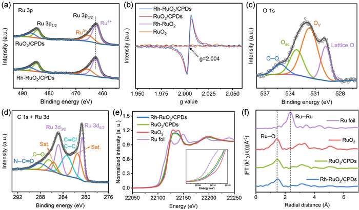
The Rh doping effect can be visually manifested in the Raman spectra. The Raman spectra of RuO2/CPDs and RuO2 presented in Fig. S9 (Supporting information) show nearly identical peak positions for Eg, A1g, and B2g modes at 505, 623, and 687 cm−1, respectively. After Rh doping, the Eg and A1g peaks in Rh-RuO2 and Rh-RuO2/CPDs display a blue shift compared to those in RuO2 and RuO2/CPDs. It can be attributed to the alteration of Ru-O symmetry induced by Rh doping [27-29]. Moreover, the absence of B2g peak in Rh-RuO2 and Rh-RuO2/CPDs confirms the substitution of Rh(Ⅲ) for Ru(Ⅳ) sites within octahedral units through cation exchange [30]. In addition, the Ru 3p spectrum of Rh-RuO2/CPDs (Fig. 2a) can be deconvoluted into Ru4+ (462.6 and 484.7 eV) and Ru3+ (487.4 and 465.6 eV) [5,8]. The fitted Ru4+ peaks in Rh-RuO2/CPDs exhibit an appreciable positive shift of 0.3 eV compared to RuO2/CPDs, indicating that Ru in Rh-RuO2/CPDs has a higher valence state. Similarly, the binding energy of Ru4+ peak in Rh-RuO2 is also slightly lower than in that in RuO2 (Fig. S10 in Supporting information), which means that Rh doping can facilitate the electrons transfer from Ru to adjacent O atoms. Besides, Rh 3d XPS spectrum of Rh-RuO2/CPDs (Fig. S11 in Supporting information) displays two peaks of Rh 3d5/2 (309.5 eV) and Rh 3d3/2 (314.1 eV). For Rh-RuO2, the peaks are located at 308.9 (Rh 3d5/2) and 313.6 eV (Rh 3d3/2). Both are lower than those of the standard Rh3+ (Rh 3d5/2 at 309.7 eV and Rh 3d3/2 at 314.5 eV), indicating that the oxidation states of Rh in both Rh-RuO2/CPDs and Rh-RuO2 are lower than +3 [31]. These combined Ru 3p and Rh 3d spectra further confirm the charges transfer through Ru-O-Rh.
Figure 2
Figure 2.
The electronic structure analysis of Rh-RuO2/CPDs. (a) High-resolution XPS spectra of Rh-RuO2/CPDs and RuO2/CPDs. (b) EPR spectra of Rh-RuO2/CPDs and the control catalysts. High-resolution XPS spectra of Rh-RuO2/CPDs: (c) O 1s region, (d) C 1s and Ru 3d regions. (e) Ru K-edge XANES spectra of Rh-RuO2/CPDs and the reference samples. (f) Fourier transform EXAFS spectra at Ru K-edge of Rh-RuO2/CPDs and the reference samples.
In particular, the reaction between the carbon core in CPDs and Ru-O (C + Ru-O → Ru-OV + CO2) results in the formation of Ru-O defects. Electron paramagnetic resonance (EPR, Fig. 2b) was used to confirm vacancy defects [10,11]. Specifically, no EPR signals were detected in RuO2 and Rh-RuO2. In contrast, Rh-RuO2/CPDs and RuO2/CPDs display a more pronounced signal at g = 2.004, which is attributable to Ru-O defects. The defective structure can be further verified by XPS spectra. As depicted in Fig. 2c, the O 1s spectrum of Rh-RuO2/CPDs can be deconvoluted into four distinct peaks positioned at 529.7, 531.6, 533.2, and 535.2 eV, corresponding to the lattice oxygen (Ru-O), oxygen vacancies (OV), surface-adsorbed oxygenous species (Oad, such as water molecule), and C–O species, respectively [13]. Significantly, OV were also detected in the O 1s XPS spectrum of RuO2/CPDs but were absent in the O 1s XPS spectra of both RuO2 and Rh-RuO2 (Fig. S12 in Supporting information). These findings are in accordance with EPR data. Furthermore, the C 1s and Ru 3d XPS spectra (Fig. 2d) exhibit that nitrogen, oxygen-associated species of CPDs including C–O and N-C=O were partially retained [19,32]. And the peaks at 280.6 and 284.8 eV, ascribable to Ru 3d5/2 and Ru 3d3/2 of the oxidation state of Ru, respectively.
More precise electronic structure information of Rh-RuO2/CPDs was explored using X-ray absorption spectroscopy (XAS). The Ru K-edge X-ray absorption near edge structure (XANES) spectra in Fig. 2e shows that the Ru K-edge absorption edge position for Rh-RuO2/CPDs lies between Ru foil and RuO2, and is close to RuO2/CPDs. This indicates that the oxidation state of Ru in Rh-RuO2/CPDs is between 0 and +4, and higher than that in RuO2/CPDs [13,33], which further confirms that Rh doping promotes a higher oxidation state of Ru. And it is consistent with the XPS results. Additionally, the Ru K-edge extended X-ray absorption fine structure spectra (EXAFS, Fig. 2f) reveal that the bond distance of Ru-O in Rh-RuO2/CPDs was slightly stretched to 1.49 Å compared with RuO2/CPDs (1.44 Å) and standard RuO2 (1.44 Å). The slight increase in the Ru-O distance is ascribed to Rh-Ru intermetallic interactions within the RuO2 lattice [8]. Moreover, the intensity of the Ru-O peaks in Rh-RuO2/CPDs is slightly lower than that of standard RuO2, demonstrating inadequate Ru-O coordination (Fig. S13 in Supporting information). The EXAFS fitting analysis at the Ru K-edge for all samples (Fig. S14 and Table S2 in Supporting information) reveals that the coordination number of Ru-O in Rh-RuO2/CPDs is 5.3, and in RuO2/CPDs it is 5.4, both of which are lower than the value of 6.0 observed in standard RuO2. This difference can primarily due to the presence of OV. Meanwhile, the Rh K-edge XANES spectra (Fig. S15 in Supporting information) indicate that the absorption threshold of Rh-RuO2/CPDs lies between that of Rh foil and Rh2O3, suggesting the valence state for Rh is between 0 and +3. And the Rh-O distance in the Rh K-edge EXAFS spectra is slightly lower than that of Rh2O3, which further proves the Ru-O-Rh interactions in RuO2 lattice.
The OER catalytic activity of Rh-RuO2/CPDs was first evaluated in 0.5 mol/L H2SO4. The linear sweep voltammetry (LSV) polarization curves (Fig. 3a) demonstrate that Rh-RuO2/CPDs exhibits an overpotential of only 168 mV at a current density of 10 mA/cm2, significantly lower than those of RuO2/CPDs (188 mV), Rh-RuO2 (297 mV), RuO2 (404 mV) and commercial RuO2 (260 mV). Accordingly, Tafel plots of the catalysts were analyzed to gain further insights into their kinetics. Among the investigated catalysts, Rh-RuO2/CPDs presents the lowest Tafel slope of 44.6 mV/dec (Fig. 3b), suggesting its superior reaction rate compared to other catalysts. Impressively, the introduction of CPDs can significantly enhance the catalytic efficiency. Furthermore, the electrochemical double-layer capacitance (Cdl) values were obtained from cyclic voltammetry (CV, Figs. S16 and S17 in Supporting information). Rh-RuO2/CPDs demonstrates a considerably high Cdl value of 107.3 mF/cm2, surpassing those of RuO2/CPDs (48.4 mF/cm2), Rh-RuO2 (8.9 mF/cm2) and RuO2 (2.1 mF/cm2). This corresponds to the largest electrochemically active surface area (ECSA) for Rh-RuO2/CPDs during OER, indicating a high density of exposed active sites that enhance OER activity. Electrochemical impedance spectroscopy (EIS) spectra (Fig. S18 in Supporting information) reveal Rh-RuO2/CPDs exhibits the best catalyst/electrolyte interface charge transfer resistance. It is worth emphasizing that CPDs significantly enhances the reactivity of Ru-O sites and plays a pivotal role in boosting the OER catalytic activity. The activity and kinetics of Rh-RuO2/CPDs were also compared with those of recently reported excellent electrocatalysts (Fig. 3c and Table S3 in Supporting information), showing a remarkable level of competitiveness.
Figure 3
Figure 3.
The electrocatalytic OER Performance of Rh-RuO2/CPDs. (a) LSV polarization curves and (b) corresponding Tafel plots for Rh-RuO2/CPDs and the other control catalysts in 0.5 mol/L H2SO4. (c) OER performance comparison of the overpotential and Tafel slope values with recently reported OER electrocatalysts in 0.5 mol/L H2SO4, with respect to Table S3. (d) Chronopotentiometry test of Rh-RuO2/CPDs at 10 mA/cm2 in 0.5 mol/L H2SO4. (e) CV analysis of redox peak of Rh-RuO2/CPDs and commercial RuO2 in 0.5 mol/L H2SO4. (f) LSV polarization curves and (g) corresponding Tafel plots for Rh-RuO2/CPDs and the other control catalysts in 1.0 mol/L KOH. (h) OER activity comparison between Rh-RuO2/CPDs and control catalysts.
Apart from intrinsic activity, the long-term stability of Rh-RuO2/CPDs was also evaluated. The chronopotentiometry test (Fig. 3d) shows that Rh-RuO2/CPDs exhibits no obvious decay at 10 mA/cm2 even after 220 h, whereas the commercial RuO2 undergoes a gradual deactivation within 10 h. In particular, Rh-RuO2/CPDs exhibits only a 6.5% performance degradation after 120 h at 100 mA/cm2 (Fig. S19 in Supporting information). TEM and XRD results (Figs. S20 and S22 in Supporting information) confirm that the catalyst maintains its original morphology and crystal structure after undergoing the 2000th CV cycle. Moreover, XPS spectra (Fig. S23 in Supporting information) reveal that the electronic structure of Ru remains almost unchanged. The stability of Ru sites during the OER was investigated by conducting CV tests to examine the oxidation behavior of Ru sites at high potential (Fig. 3e). Commercial RuO2 displays three sets of redox peaks at approximately 0.6, 1.2, and 1.45 V, corresponding to the Ru3+/Ru4+, Ru4+/Ru6+ and Ru6+/Ru8+, respectively [8,34]. For Rh-RuO2/CPDs, the Ru3+/Ru4+ peak is more dominant, indicating an oxidation state of Ru between +3 and +4, consistent with XPS and XANES analyses. The absence of Ru4+/Ru6+ and Ru6+/Ru8+ redox peaks signifies that Rh-RuO2/CPDs maintains a stable structure and prevents the over-oxidation of Ru even at the high potential. Furthermore, commercial RuO2 shows a noticeable non-coincidence in forward and reverse CV scans from 1.35 V to 1.40 V (Fig. S24 in Supporting information), suggesting an irreversible surface collapse and dissolution into soluble RuO4 [35]. Conversely, the forward and reverse scanning curves of Rh-RuO2/CPDs coincide in this voltage range, indicating significant inhibition of Ru over-oxidation. The percentage of Ru dissolution was determined by inductively coupled plasma mass spectrometry (ICP-MS) during the chronopotentiometry tests. As shown in Fig. S25 (Supporting information), the dissolved Ru increases slightly to 3.0% after 140 h, and remained plateaued even after 200 h (3.3%), indicating the highly stability of surface Ru in Rh-RuO2/CPDs. However, Rh-RuO2 shows 44.0% Ru dissolution within 10 h of the OER test, exhibiting poor corrosion resistance. It is noteworthy that the confinement effect of CPDs significantly mitigates Ru over-oxidation during the OER process, thereby enhancing its stability.
The Rh-RuO2/CPDs catalyst also exhibits superior OER performance in the alkaline media. In 1.0 mol/L KOH electrolyte, Rh-RuO2/CPDs requires an overpotential of 197 mV at 10 mA/cm2, with the corresponding Tafel slope of 72.3 mV/dec (Figs. 3f-h), which are significantly lower compared to RuO2/CPDs, Rh-RuO2, RuO2 and commercial RuO2. The EIS spectra (Fig. S26 in Supporting information) further substantiate the favorable charge transfer process of Rh-RuO2/CPDs. And the fitted Cdl values (Figs. S27 and S28 in Supporting information) indicate a greater abundance of catalytic active sites for Rh-RuO2/CPDs compared to other control catalysts. These results also show that CPDs and Rh doping can significantly improve the OER activity of Ru active sites. Additionally, the OER activity of Rh-RuO2/CPDs also surpasses that of many recently reported state-of-the-art OER catalysts (Table S4 in Supporting information). Subsequently, we investigated the long-term electrochemical stability through the chronopotentiometry test (Figs. S30 and S31 in Supporting information). Rh-RuO2/CPDs demonstrate outstanding durability for alkaline OER over a period of 150 and 80 h at 10 and 100 mA/cm2, respectively. Additionally, TEM, XRD and XPS results (Figs. S21-S23 in Supporting information) show the maintenance of stable electronic structure throughout the long-term OER process.
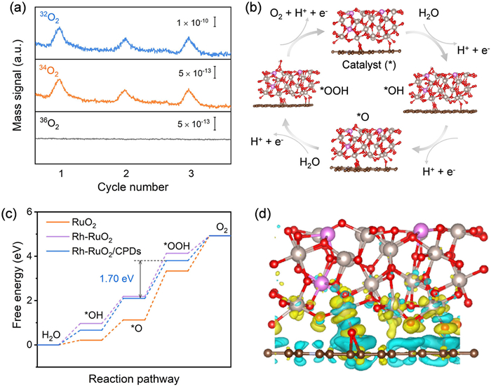
For the catalytic reaction mechanism of the four-step OER process, the traditional adsorption evolution mechanism (AEM) and lattice oxygen mediated mechanism (LOM) are considered [36]. In order to investigate the specific pathway of reaction mechanism, we conducted the in situ differential electrochemical mass spectrometry (DEMS), coupled with the 18O isotope-labeling experiment (see details in Supporting information). Fig. 4a shows that in the 18O-labeled Rh-RuO2/CPDs system in H216O electrolyte, the ratio of 34O2 (16O18O) to 32O2 (16O16O) in gaseous products is 0.45%. Considering the natural abundance of 18O in water is about 0.2% [37], the detected 34O2 level of approximately 0.4% confirms that the Rh-RuO2/CPDs catalyst follows the conventional AEM pathway, excluding lattice oxygen involvement during electrocatalysis. Besides, both Rh-RuO2 and RuO2 without oxygen vacancies also favor the AEM path during the OER process [5,27]. To gain a deeper insight on the electronic structures of Rh-RuO2/CPDs, we conducted density functional theory (DFT) calculations. Three structural models based on the (101) surface of RuO2 were constructed to investigate the effect of Rh dopant and the introduction of CPDs. These models represent the experimentally synthesized composite structures of RuO2, Rh-RuO2 and Rh-RuO2/CPDs, respectively (Fig. S32 in Supporting information). Specifically, the OER path proceeds through a four-proton-coupled electron transfer mechanism of AEM that involves *OH, *O and *OOH intermediates (Fig. 4b) [10,33]. The calculated free energy diagrams for OER (Fig. 4c) indicates the rate-determining step (RDS) is the formation of *OOH. The calculated free energy of the RDS for Rh-RuO2/CPDs is 1.70 eV, lower than that of Rh-RuO2 (1.94 eV) and RuO2 (2.21 eV). This suggests that Rh-RuO2/CPDs provides a more energetically favorable OER pathway, which is consistent with experimental results. This analysis can well explain why the Rh-RuO2/CPDs exhibits significantly enhanced OER catalytic activity compared to Rh-RuO2 and RuO2. Therefore, it can be concluded that the Rh doping and the introduction of CPDs play a crucial role in enhancing the OER activity of RuO2. Additionally, the charge density difference analysis was also conducted to further study the charge redistribution on Rh-RuO2/CPDs. As depicted in Fig. 4d, the electron transfer from the Rh-doped RuO2 nanoparticles to CPDs, which not only increases the oxidation states of Ru at the active sites but also promotes the electronic coupling between RuO2 and CPDs. Additionally, the energy costs of deoxygenation (the oxidative release of lattice oxygen, EO) and the Ru demetallation (the dissolution of surface Ru, ERu) were calculated. As shown in Fig. S33 (Supporting information), the EO and ERu of Rh-RuO2/CPDs are 0.83 and 3.61 eV, respectively. Both are higher than those of Rh-RuO2 (0.80 and 2.65 eV). It further demonstrates that the electronic structure modulation of CPDs can enhance the stability of lattice oxygen and surface Ru during the OER pathway. Based on these results, CPDs-modificated Ru-O active sites and further Rh doping can synergistically regulate the coordination environment and electronic structure of active Ru-O center to optimize the binding configuration of OER intermediates, thereby accounting for the optimal OER activity for Rh-RuO2/CPDs.
Figure 4
Figure 4.
Catalytic mechanism and density functional theory calculation. (a) DEMS signals of O2 products for 18O-labeled Rh-RuO2/CPDs in H216O electrolyte. (b) Schematic illustration of AEM for OER on Rh-RuO2/CPDs. (c) Calculated free energy diagrams for OER pathways of Rh-RuO2/CPDs, Rh-RuO2 and RuO2. (d) Differential charge density analysis of Rh-RuO2/CPDs system. The blue and yellow shaded areas represent regions of electron density accumulation and depletion, respectively.
In summary, by utilizing the distinct structural and electronic properties of CPDs, we have successfully designed and synthesized the ultrafine and defective Rh-RuO2/CPDs electrocatalyst. Specially, CPDs induce the formation of chemically stable lattice oxygen and defects in the Rh-RuO2/CPDs system, which plays an essential role in enhancing the activity and stability of Ru-O-Rh sites for OER. Furthermore, the experiment results and DFT analysis reveal that Rh doping and the modification of CPDs on Ru-O active sites enhance the electron transfer at the interface and optimize the intermediate kinetics of OER pathway. Thus, the developed Rh-RuO2/CPDs catalyst only needs low OER overpotentials of 168 and 197 mV at 10 mA/cm2 in 0.5 mol/L H2SO4 and 1.0 mol/L KOH, respectively, along with long-term stability, which outperform the commercial RuO2 and many reported OER electrocatalysts. This work offers a prospective approach for design and construction of advanced OER catalysts.
Declaration of competing interest
The authors declare that they have no known competing financial interests or personal relationships that could have appeared to influence the work reported in this paper.
CRediT authorship contribution statement
Da Yue: Writing – original draft, Software, Methodology, Investigation, Formal analysis, Data curation. Tanglue Feng: Writing – review & editing, Methodology, Conceptualization. Zhicheng Zhu: Writing – review & editing, Software, Data curation. Mingcheng Zhang: Data curation. Liyuan Chen: Data curation. Xiao Han: Data curation. Haizhu Sun: Writing – review & editing. Bai Yang: Writing – review & editing, Project administration, Funding acquisition, Conceptualization.
Acknowledgments
This work was financially supported by the National Natural Science Foundation of China (No. 22035001) and the Natural Science Foundation of Jilin Province (No. ***202402011).
Supplementary materials
Supplementary material associated with this article can be found, in the online version, at doi:10.1016/j.cclet.2025.111393.
[1]
Z.W. Seh, J. Kibsgaard, C.F. Dickens, et al., Science 355 (2017) 146. doi: 10.1126/science.aad4998
L. Wang, R. Du, X. Liang, et al., Adv. Mater. 36 (2024) 2312608. doi: 10.1002/adma.202312608
Figure 1
The synthesis process, morphology and structural characterizations of Rh-RuO2/CPDs. (a) Schematic diagram of the synthesis and structure of Rh-RuO2/CPDs. (b) XRD patterns of Rh-RuO2/CPDs and the control catalysts. (c) TEM and (d) HR-TEM images of Rh-RuO2/CPDs. (e) The magnified HAADF-STEM image of Rh-RuO2/CPDs. (f) The HAADF-STEM image and the corresponding EDX mapping images of Rh-RuO2/CPDs.
Figure 2
The electronic structure analysis of Rh-RuO2/CPDs. (a) High-resolution XPS spectra of Rh-RuO2/CPDs and RuO2/CPDs. (b) EPR spectra of Rh-RuO2/CPDs and the control catalysts. High-resolution XPS spectra of Rh-RuO2/CPDs: (c) O 1s region, (d) C 1s and Ru 3d regions. (e) Ru K-edge XANES spectra of Rh-RuO2/CPDs and the reference samples. (f) Fourier transform EXAFS spectra at Ru K-edge of Rh-RuO2/CPDs and the reference samples.
Figure 3
The electrocatalytic OER Performance of Rh-RuO2/CPDs. (a) LSV polarization curves and (b) corresponding Tafel plots for Rh-RuO2/CPDs and the other control catalysts in 0.5 mol/L H2SO4. (c) OER performance comparison of the overpotential and Tafel slope values with recently reported OER electrocatalysts in 0.5 mol/L H2SO4, with respect to Table S3. (d) Chronopotentiometry test of Rh-RuO2/CPDs at 10 mA/cm2 in 0.5 mol/L H2SO4. (e) CV analysis of redox peak of Rh-RuO2/CPDs and commercial RuO2 in 0.5 mol/L H2SO4. (f) LSV polarization curves and (g) corresponding Tafel plots for Rh-RuO2/CPDs and the other control catalysts in 1.0 mol/L KOH. (h) OER activity comparison between Rh-RuO2/CPDs and control catalysts.
Figure 4
Catalytic mechanism and density functional theory calculation. (a) DEMS signals of O2 products for 18O-labeled Rh-RuO2/CPDs in H216O electrolyte. (b) Schematic illustration of AEM for OER on Rh-RuO2/CPDs. (c) Calculated free energy diagrams for OER pathways of Rh-RuO2/CPDs, Rh-RuO2 and RuO2. (d) Differential charge density analysis of Rh-RuO2/CPDs system. The blue and yellow shaded areas represent regions of electron density accumulation and depletion, respectively.


 DownLoad:


 下载:
下载:


 下载:
下载:
